MLFA Series
Stackpole Electronics, Inc.
Metal Film Melf Resistor – AEC-Q200 Qualified
Resistive Product Solutions
Features:
•
•
•
•
•
•
•
•
•
•
•
Thin film technology for precision and stability
Excellent power to size ratio
Outstanding pulse handling
Excellent overall stability
Sn termination on Ni barrier layer
Tight tolerance down to ± 0.1%
Extremely low TCR down to ± 5 ppm/ºC
High power rating up to 1 W
SMD enabled structure
AEC-Q200 compliance
RoHS compliant, lead free and halogen free
Electrical Specifications
Type / Code
Package
Size
Power Rating
(Watts)
@ 70 ºC
Maximum
Working
(1)
Maximum
Overload
TCR (ppm/ºC)
(2)
Ohmic Range (Ω) and Tolerance
0.1%
± 50
0.3
0102
200
400
± 100
MLFA13(3)
Jumper: 2 A
±5
10 - 332 K
± 15
0.4
± 25
10 - 1 M
MLFA25
0204
200
400
± 50
10 - 1 M
± 100
Jumper: 3 A
±5
10 - 332 K
± 15
1
± 25
10 - 1 M
MLFA1
0207
350
700
± 50
10 - 1 M
± 100
Jumper: 5 A
(1)
Working Voltage = √ (P*R) or Max. Operating Voltage listed above, whichever is lower.
(2)
Overload Voltage = 2.5*√(P*R) or Max. Overload Voltage listed above, whichever is lower.
(3)
Lower TCR with lower Power Ratings may be available - contact Stackpole
RCWV (Rated Continuous Working Voltage) = √(P*R) or Max Operating Voltage, whichever is lower.
Voltage
Voltage
0.5%
1%
1-1M
5%
1-1M
0 Ω (< 15mΩ)
10 - 300 K
10 - 3.4 M
1 - 3.4 M
1 - 3.4 M
0.2 - 3.4 M
0.1 - 1 M
0 Ω (< 15mΩ)
10 - 300 K
10 - 3.4 M
1 - 3.4 M
1 - 3.4 M
0.2 - 3.4 M
0.1 - 1 M
0 Ω ( 15 mΩ)
Mechanical Specifications
Type / Code
Weight (g)
(1000 pc)
L
Body Length
0.087 ± 0.004
2.20 ± 0.10
MLFA13
7.7
MLFA25
18.7
0.138 ± 0.008
3.50 ± 0.20
MLFA1
80.9
0.232 ± 0.008
5.90 ± 0.20
L1 (min.)
Inner Body Length
0.043
1.10
0.067
1.70
0.114
2.90
Rev Date: 08/12/2020
This specification may be changed at any time without prior notice
Please confirm technical specifications before you order and/or use.
1
D
Body Diameter
0.043 ± 0.004
1.10 ± 0.10
0.055 ± 0.006
1.40 ± 0.15
0.087 ± 0.008
2.20 ± 0.20
D1
Middle Body Dia.
0.043 +0/-0.006
1.10 +0/-0.15
0.055 +0/-0.008
1.40 +0/-0.2
0.087 +0/-0.008
2.20 +0/-0.2
K
Termination
0.018 ± 0.002
0.45 ± 0.05
inches
mm
0.031 ± 0.004
0.80 ± 0.10
inches
mm
0.051 ± 0.004
1.30 ± 0.10
inches
mm
Unit
www.seielect.com
marketing@seielect.com
�MLFA Series
Stackpole Electronics, Inc.
Metal Film Melf Resistor – AEC-Q200 Qualified
Resistive Product Solutions
Performance Characteristics
Test
Temperature
Coefficient of
Resistance (T.C.R.)
Test Method
Test Method
JIS-C-5201-1 4.8
IEC-60115-1 4.8
At 25°C / - 55°C and 25°C / + 125°C, 25°C
is the reference temperature.
5ppm: At 25°C / -10°C and 25°C / +85°C,
25°C is the reference temperature
Test Specification
5% and below
Jumper
As specified
10 Ω - 270 KΩ: ± (0.1% + 0.01 Ω)
Short Time Overload
JIS-C-5201-1 4.13
IEC-60115-1 4.13
RCWV*2.5 or max. overload voltage
whichever is lower for 5 seconds
< 10 Ω & > 270 KΩ: ± (0.15% + 0.01 Ω)
< 15 mΩ
MLFA13: ± (0.15% + 0.01 Ω)
5 ppm/ºC: ± (0.05% + 0.01 Ω)
JIS-C-5201-1 4.6
IEC-60115-1 4.6
Max. overload voltage for 1 minute
Operational Life
MIL-STD-202
Method 108
Condition D Steady State TA = 125°C at
derated power. Measurement at 24 ± 4
hours after test conclusion.
5 ppm/ºC: 70 ± 2°C, RCWV for 1000 hours
with 1.5 hours "ON" and 0.5 hour "OFF"
Biased Humidity
MIL-STD-202
Method 103
1000 hours 85°C / 85% R.H. 10% of
operating power
High Temperature
Exposure
MIL-STD-202
Method 108
at +125°C / +155°C for 1000 hours
Board Flex
AEC-Q200-005
Bending once for 60 seconds with 2 mm
Solderability
JIS-5201-1 4.17
IEC 60115-1 4.17
J-STD 002
245 ± 5°C for 3 seconds
95% min. coverage
Resistance to
Soldering Heat
MIL-STD-202
Method 210
260 ± 5°C for 10 seconds
10 Ω - 270 KΩ: ± (0.1% + 0.01 Ω)
< 10 Ω & > 270 KΩ: ± 0.25% + 0.01 Ω)
< 15 mΩ
MLFA13: ± (0.25% + 0.01 Ω)
5 ppm/ºC: ± (0.05% + 0.01 Ω)
1.42 times max. operating voltage for 1
minute
No breakdown or flashover
Insulation Resistance
Voltage Proof
Leaching
Temperature Cycling
JIS-C-5201-1 4.7
IEC 60115-1 4.7
JIS-C-5201-1 4.18
IEC-60068-2-58 8.2.1
JESD22
Method JA-104
260 ± 5ºC for 30 seconds
-55°C to + 125°C, 1000 cycles
≥10G
10 Ω - 270 KΩ: ± (0.25% + 0.01 Ω)
270 KΩ: ± (0.5% + 0.01 Ω)
MLFA13: ± (0.5% + 0.01 Ω)
< 15 mΩ
10 Ω - 270 KΩ: ± (0.5% + 0.01 Ω)
< 10 Ω & > 270 K Ω: ± (1% + 0.01 Ω) < 15 mΩ
MLFA13: ± (2% + 0.01 Ω)
10 Ω - 270 K Ω: ± (0.25% + 0.01 Ω)
< 10 Ω & > 270 KΩ: ± (1% + 0.01 Ω) < 15 mΩ
MLFA13: ± (1% + 0.01 Ω)
10 Ω - 270 KΩ: ± (0.1% + 0.01 Ω)
< 10 Ω & > 270 KΩ: ± (0.5% + 0.01 Ω) < 15 mΩ
MLFA13: ± (0.5% + 0.01 Ω)
Individual leaching area ≤ 5%
Total leaching area ≤ 10%
10 Ω - 270 KΩ: ± (0.25% + 0.01 Ω)
< 10 Ω & > 270 KΩ: ± 0.5% + 0.01 Ω) < 15 mΩ
MLFA13: ± (1% + 0.01 Ω)
Wave Form: Tolerance for half sine shock
± (0.25% + 0.01 Ω)
< 15 mΩ
pulse. 'Peak value is 100 g's. Normal
duration (D) is 6.
5 g's for 20 minutes.,
MIL-STD-202
Vibration
± (0.5% + 0.01 Ω)
< 15 mΩ
12 cycles each of 3 orientations
Method 204
10-2000 Hz
ESD
AEC-Q200-002
Human body, 2 KV
± (0.5% + 0.05 Ω)
< 15 mΩ
Resistance to
MIL-STD-202
Add aqueous wash chemical - OKEM clean
No visible damage on appearance and marking.
Solvents
Method 215
or equivalent. Do not use banned solvents.
Terminal Strength
AEC-Q200-006
Force of 1.8 Kg for 60 seconds
No breakage
V - 0 or V - 1 are acceptable.
No ignition of the tissue paper or scorching of the
Flammability
UL-94
Electrical test not required.
pinewood board
RCWV (rated continuous working voltage) = √(P*R) or max. operating voltage whichever is lower
Storage temperature: 15 ~ 28ºC. Humidity < 80% R.H.
Operating temperature range is -55°C to +125°C for 5 ppm/ºC
Operating temperature range is -55°C to +155°C for all others except 5 ppm/ºC
Mechanical Shock
MIL-STD-202
Method 213
Rev Date: 08/12/2020
This specification may be changed at any time without prior notice
Please confirm technical specifications before you order and/or use.
2
www.seielect.com
marketing@seielect.com
�MLFA Series
Stackpole Electronics, Inc.
Metal Film Melf Resistor – AEC-Q200 Qualified
Resistive Product Solutions
Power Derating Curve:
Percent Rated Power (%)
100
-55ºC
70ºC
5ppm
except for 5ppm
80
60
40
20
125°C
0
-60
0
20
40
60
80
100
120
Ambient Temperature (ºC)
155ºC
140
160
180
Hot Spot Temperature:
Reel Specifications
Type / Code
MLFA13
MLFA25
MLFA1
øA
Reel Diameter
0.276
7.00
0.276
7.00
0.276
7.00
7.028
178.50
7.028
178.50
7.028
178.50
±
±
±
±
±
±
øB
0.059
1.50
0.059
1.50
0.059
1.50
2.362
60.00
2.362
60.00
2.362
60.00
Rev Date: 08/12/2020
This specification may be changed at any time without prior notice
Please confirm technical specifications before you order and/or use.
±
±
±
±
±
±
øC
0.039
1.00
0.039
1.00
0.039
1.00
3
0.512
13.00
0.512
13.00
0.512
13.00
±
±
±
±
±
±
W
0.008
0.20
0.008
0.20
0.020
0.50
0.354
9.00
0.354
9.00
0.512
13.00
±
±
±
±
±
±
T
0.020
0.50
0.020
0.50
0.020
0.50
0.492
12.50
0.492
12.50
0.610
15.50
±
±
±
±
±
±
Unit
0.020
0.50
0.020
0.50
0.020
0.50
inches
mm
inches
mm
inches
mm
www.seielect.com
marketing@seielect.com
�MLFA Series
Stackpole Electronics, Inc.
Metal Film Melf Resistor – AEC-Q200 Qualified
Resistive Product Solutions
Packaging Specifications - Embossed Plastic Tape
Type / Code
MLFA13
MLFA25
MLFA1
A
0.051
1.30
0.061
1.55
0.094
2.40
Type / Code
MLFA13
MLFA25
MLFA1
±
±
±
±
±
±
B
0.004
0.10
0.004
0.10
0.004
0.10
0.094
2.40
0.144
3.65
0.242
6.15
0.004
0.10
0.004
0.10
0.004
0.10
0.079
2.00
0.079
2.00
0.079
2.00
P1
0.157
4.00
0.157
4.00
0.157
4.00
±
±
±
±
±
±
±
±
±
±
±
±
W
0.004
0.10
0.004
0.10
0.004
0.10
0.315
8.00
0.315
8.00
0.472
12.00
0.002
0.05
0.002
0.05
0.002
0.05
0.059
1.50
0.059
1.50
0.059
1.50
P2
±
±
±
±
±
±
±
±
±
±
±
±
E
0.004
0.10
0.004
0.10
0.004
0.10
D0
±
±
±
±
±
±
0.069
1.75
0.069
1.75
0.069
1.75
±
±
±
±
±
±
F
0.004
0.10
0.004
0.10
0.004
0.10
0.138
3.50
0.138
3.50
0.217
5.50
±
±
±
±
±
±
min.
min.
min.
min.
min.
min.
0.059
1.50
0.071
1.80
0.106
2.70
±
±
±
±
±
±
D1
0.004
0.10
0.004
0.10
0.004
0.10
0.035
0.90
0.035
0.90
0.055
1.40
P0
0.002
0.05
0.002
0.05
0.002
0.05
T
0.157
4.00
0.157
4.00
0.157
4.00
±
±
±
±
±
±
Unit
0.004
0.10
0.004
0.10
0.004
0.10
inches
mm
inches
mm
inches
mm
Unit
0.004
0.10
0.004
0.10
0.004
0.10
inches
mm
inches
mm
inches
mm
Recommended Pad Layout
Type / Code
MLFA13
MLFA25
MLFA1
A
0.039
1.00
0.063
1.60
0.118
3.00
Rev Date: 08/12/2020
This specification may be changed at any time without prior notice
Please confirm technical specifications before you order and/or use.
B
0.031
0.80
0.047
1.20
0.067
1.70
4
C
0.059
1.50
0.063
1.60
0.094
2.40
Unit
inches
mm
inches
mm
inches
mm
www.seielect.com
marketing@seielect.com
�MLFA Series
Stackpole Electronics, Inc.
Metal Film Melf Resistor – AEC-Q200 Qualified
Resistive Product Solutions
Soldering Condition:
(1) Time of IR reflow soldering at maximum temperature point 260°C: 10 seconds
(2) Time of wave soldering at maximum temperature point 260°C: 10 seconds
(3) Time of soldering iron at maximum temperature point 410°C: 5 seconds
Pulse Withstanding Capacity
The single impulse graph is the result of the impulse of rectangular shape applied. The limit of acceptance was a shift
in resistance of less than 1% from the initial value. The power applied was subject to the restrictions of the maximum
permissible impulse voltage graph shown.
Rev Date: 08/12/2020
This specification may be changed at any time without prior notice
Please confirm technical specifications before you order and/or use.
5
www.seielect.com
marketing@seielect.com
�MLFA Series
Stackpole Electronics, Inc.
Metal Film Melf Resistor – AEC-Q200 Qualified
Resistive Product Solutions
Continuous Pulse
The continuous load graph was obtained by applying repetitive rectangular pulses where the pulse period was adjusted
so that the average power dissipated in the resistor was equal to its rated power at 70ºC. Again the limit of acceptance
was a shift in resistance of less than 1% from the initial value.
Rev Date: 08/12/2020
This specification may be changed at any time without prior notice
Please confirm technical specifications before you order and/or use.
6
www.seielect.com
marketing@seielect.com
�MLFA Series
Stackpole Electronics, Inc.
Metal Film Melf Resistor – AEC-Q200 Qualified
Resistive Product Solutions
Frequency Behavior
Resistors are designed to function according to Ohmic laws. This is basically true of resistors for frequencies up to 100
kHz. At higher frequencies, there is an additional contribution to the impedance by an ideal resistor switched in series
with a coil and both switched parallel to a capacitor. The values of the capacitance and inductance are mainly determined
by the dimensions of the terminations and the conductive path length. The environment surrounding components has a
large influence on the behavior of the component on the printed-circuit board.
MLFA25 Frequency versus Impedance
Rev Date: 08/12/2020
This specification may be changed at any time without prior notice
Please confirm technical specifications before you order and/or use.
7
www.seielect.com
marketing@seielect.com
�MLFA Series
Stackpole Electronics, Inc.
Metal Film Melf Resistor – AEC-Q200 Qualified
Resistive Product Solutions
MLFA25 Frequency versus Phase Angle
MLFA1 Frequency versus Impedance
Rev Date: 08/12/2020
This specification may be changed at any time without prior notice
Please confirm technical specifications before you order and/or use.
8
www.seielect.com
marketing@seielect.com
�MLFA Series
Stackpole Electronics, Inc.
Metal Film Melf Resistor – AEC-Q200 Qualified
Resistive Product Solutions
MLFA1 Frequency versus Phase Angle
Lightning Surge
Resistors are tested in accordance with IEC 60 115-1 using both 1.2 / 50 µs and 10 / 700 µs pulse shapes. The limit of
acceptance is a shift in resistance of less than 0.5% from the initial value.
MLFA25 / MLFA1 1.2 / 50 μs Lightning Surge
Rev Date: 08/12/2020
This specification may be changed at any time without prior notice
Please confirm technical specifications before you order and/or use.
9
www.seielect.com
marketing@seielect.com
�MLFA Series
Stackpole Electronics, Inc.
Metal Film Melf Resistor – AEC-Q200 Qualified
Resistive Product Solutions
10 / 700 μs Lightning Surge
MLFA13 1.2 / 50 µs Lightning Surge
Rev Date: 08/12/2020
This specification may be changed at any time without prior notice
Please confirm technical specifications before you order and/or use.
10
www.seielect.com
marketing@seielect.com
�MLFA Series
Stackpole Electronics, Inc.
Metal Film Melf Resistor – AEC-Q200 Qualified
Resistive Product Solutions
MLFA13 10 / 700 µs Lightning Surge
RoHS Compliance
Stackpole Electronics has joined the worldwide effort to reduce the amount of lead in electronic components and to meet the various
regulatory requirements now prevalent, such as the European Union’s directive regarding “Restrictions on Hazardous Substances”
(RoHS 3). As part of this ongoing program, we periodically update this document with the status regarding the availability of our
compliant components. All our standard part numbers are compliant to EU Directive 2011/65/EU of the European Parliament as
amended by Directive (EU) 2015/863/EU as regards the list of restricted substances.
RoHS Compliance Status
Standard
Product
Series
MLFA
Description
Package /
Termination
Type
Standard
Series
RoHS
Compliant
Lead-Free Termination
Composition
Lead-Free
Mfg. Effective Date
(Std Product Series)
Lead-Free
Effective Date
Code
(YY/WW)
Metal Film Melf Resistor
(AEC-Q200 Qualified)
SMD
YES
100% Matte Sn
Always
Always
Conflict Metals” Commitment
We at Stackpole Electronics, Inc. are joined with our industry in opposing the use of metals mined in the “conflict region” of the eastern
Democratic Republic of the Congo (DRC) in our products. Recognizing that the supply chain for metals used in the electronics industry
is very complex, we work closely with our own suppliers to verify to the extent possible that the materials and products we supply do
not contain metals sourced from this conflict region. As such, we are in compliance with the requirements of Dodd-Frank Act regarding
Conflict Minerals.
Compliance to “REACH”
We certify that all passive components supplied by Stackpole Electronics, Inc. are SVHC (Substances of Very High Concern) free and
compliant with the requirements of EU Directive 1907/2006/EC, “The Registration, Evaluation, Authorization and Restriction of
Chemicals”, otherwise referred to as REACH. Contact us for complete list of REACH Substance Candidate List.
Rev Date: 08/12/2020
This specification may be changed at any time without prior notice
Please confirm technical specifications before you order and/or use.
11
www.seielect.com
marketing@seielect.com
�MLFA Series
Stackpole Electronics, Inc.
Metal Film Melf Resistor – AEC-Q200 Qualified
Resistive Product Solutions
Environmental Policy
It is the policy of Stackpole Electronics, Inc. (SEI) to protect the environment in all localities in which we operate. We continually strive
to improve our effect on the environment. We observe all applicable laws and regulations regarding the protection of our environment
and all requests related to the environment to which we have agreed. We are committed to the prevention of all forms of pollution.
How to Order
1
2
3
4
5
6
7
8
10
11
12
13
14
M
L
F
A
2
5
F
T
S
1
0
0
K
Product Series
MLFA
Power Rating
Code Size W
13 0102 0.3
25 0204 0.4
1 0207 1
Tolerance
Packaging
TCR
Code Tol
Value
Code Description Product Code Quantity Code ppm
B
0.1%
MLFA13
Z jumper
7" Reel
3000
T
D
0.5% E96, E24
MLFA25
Y
5
Plastic Tape
F
1%
MLFA1
2000
S
15
J
5%
E24
E
25
Z Jumper
C
50
D
100
Rev Date: 08/12/2020
This specification may be changed at any time without prior notice
Please confirm technical specifications before you order and/or use.
12
Resistance Value
Four characters with the
multiplier used as the
decimal holder.
1 ohm = 1R00
100 Kohm = 100K
1 Mohm = 1M00
zero ohm jumper = 0R00
www.seielect.com
marketing@seielect.com
�
很抱歉,暂时无法提供与“MLFA1FTC10R0”相匹配的价格&库存,您可以联系我们找货
免费人工找货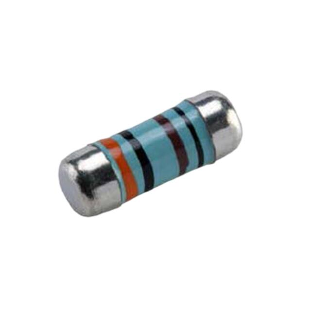


 工商网监
湘ICP备2023018690号
工商网监
湘ICP备2023018690号
