ADVANCE INFORMATION — CONFIDENTIAL AND PROPRIETARY — DO NOT DISTRIBUTE
QMI8658C — 6D Inertial Measurement Unit with Motion Co-Processor
QMI8658C DATASHEET
JANUARY 13, 2021
QST SOLUTIONS LIMITED
120 BAYTECH DR, SAN JOSE, CA 95134
© 2021 QST Corporation
QMI8658C • Rev 0.6
www. qstcorp.com
�ADVANCE INFORMATION — CONFIDENTIAL AND PROPRIETARY — DO NOT DISTRIBUTE
Features
Description
Low 15 mdps/√Hz gyroscope noise, low-latency,
and wide bandwidth for performance applications
such robotic vacuums, industrial tilt modules,
pedestrian navigation and GNSS augmentation, 5G
antenna stabilization, inertial navigation, and large
industrial UAVs
Low Noise 200µg/√Hz accelerometer
The QMI8658C is a complete 6D MEMS inertial
measurement unit (IMU) with 9-axis sensor fusion and
specified system level orientation accuracy. When using
the QMI8658C in combination with the supplied XKF3
9D-sensor fusion, the system features an accurate ±3°
pitch and roll orientation, and a ±5° yaw/heading typical
specification.
Host (slave) interface supports MIPI™ I3C, I2C, and
3-wire or 4-wire SPI; auxiliary master I2C interface
supports an external magnetometer
With tight board-level gyroscope sensitivity of ±3%,
gyroscope noise density of 15 mdps/√Hz, and low
latency, the QMI8658C is ideal for high performance
consumer and for industrial applications.
Accelerometer and gyroscope sensors feature
signal processing paths with digitally programmable
data rates and filtering
Complete inertial measurement unit (IMU) with
sensor fusion library with specified orientation
accuracy of ±3º pitch and roll, ±5º yaw/heading
High-performance XKF3TM 6/9-axis sensor fusion
with in-run calibration for correction of gyroscope
bias drift over-temperature and lifetime
3-axis gyroscope and 3-axis accelerometer in a
small 2.5 x 3.0 x 0.86 mm 14-pin LGA package
Integrated Gen 2 AttitudeEngineTM motion coprocessor with vector DSP performs sensor fusion
at 1 kHz sampling rate, while outputting data to host
processor at a lower rate – improving accuracy
while reducing processor MIPS, power, and
interrupt requirements
Large 1536-byte FIFO can be used to buffer sensor
data to lower system power dissipation
This enables the application to utilize low output data
rates (ODRs) or on-demand (host polling) while still
acquiring accurate 3D motion data. The AttitudeEngine
reduces the data processing and interrupt load on a host
processor with no compromises in 3D motion tracking
accuracy. The result is very low total system power in
combination with high accuracy, which are essential to
many portable and battery powered applications.
Motion on demand technology for polling-based
synchronization
Applications
Large sensor dynamic ranges from ±16°/s to
±2048°/s for gyroscope and ±2 g to ±16 g for
accelerometer
Low power modes for effective power management
Digitally programmable sampling rate and filters
The QMI8658C incorporates a 3-axis gyroscope and a 3axis accelerometer. It provides a UI interface (supporting
I3C, I2C and 3-wire or 4-wire SPI) and a second interface
functioning as an I2C master for communicating to an
external magnetometer.
The QMI8658C incorporates an advanced vector digital
signal processor (DSP) motion co-processor called the
AttitudeEngine. The AttitudeEngine efficiently encodes
high frequency motion at high internal sampling rates,
preserving full accuracy across lower-frequency output
data rates.
Toys
Drones
E-bikes and scooters
Motion-based remote controls and air mice
Embedded temperature sensor
Wide extended operating temperature range
(-40°C to 85°C)
© 2021 QST Corporation
QMI8658C • Rev 0.6
www. qstcorp.com
1
QMI8658C — 6D Inertial Measurement Unit with Motion Co-Processor
QMI8658C
Low Noise, Wide Bandwidth 6D Inertial Measurement
Unit with Motion Co-Processor and Sensor Fusion
�ADVANCE INFORMATION — CONFIDENTIAL AND PROPRIETARY — DO NOT DISTRIBUTE
1
2
3
General Information ........................................................................................................ 4
1.1
1.2
1.3
1.4
1.5
1.6
QMI8658C Architecture ................................................................................................. 10
2.1
2.2
2.3
2.4
5
6
7
AttitudeEngine Mode Overview......................................................................................... 10
Advantages of the Attitude Engine Approach .................................................................... 10
9D Sensor Fusion and Auto-Calibration using XKF3 ............................................................ 11
Frames of Reference and Conventions for Using QMI8658C ............................................... 12
System, Electrical and Electro-Mechanical Characteristics ............................................. 13
3.1
3.2
3.3
3.4
3.5
3.6
3.7
3.8
4
Ordering Information .......................................................................................................... 4
Marking Information ........................................................................................................... 4
Internal Block Diagram ........................................................................................................ 5
Interface Operating Modes .................................................................................................. 6
Package & Pin Information .................................................................................................. 7
Recommended External Components .................................................................................. 9
Absolute Maximum Ratings ............................................................................................... 13
Recommended Operating Conditions ................................................................................ 13
System Level Specifications ............................................................................................... 14
Electro-Mechanical Specifications ...................................................................................... 15
Accelerometer Programmable Characteristics ................................................................... 17
Gyroscope Programmable Characteristics .......................................................................... 18
Electrical Characteristics .................................................................................................... 19
Current Consumption ............................................................................................................ 19
Temperature Sensor .......................................................................................................... 20
Register Map Overview .................................................................................................. 21
4.1
UI Register Map Overview ................................................................................................. 21
UI Sensor Configuration Settings and Output Data......................................................... 24
5.1
5.2
5.3
5.4
5.5
5.6
5.7
5.8
Typical Sensor Mode Configuration and Output Data ........................................................ 24
AttitudeEngine (AE) Mode Configuration and Output Data ................................................ 25
General Purpose Register .................................................................................................. 25
Configuration Registers ..................................................................................................... 26
FIFO Registers .................................................................................................................... 30
Status and Time Stamp Registers ....................................................................................... 32
Sensor Data Output Registers ............................................................................................ 34
CTRL 9 Functionality (Executing Pre-defined Commands) ................................................... 37
CTRL 9 Description ................................................................................................................ 37
WCtrl9 (Write – CTRL9 Protocol)........................................................................................... 37
Ctrl9R (CTRL9 Protocol - Read) .............................................................................................. 38
Ctrl9 (CTRL9 Protocol Acknowledge) .................................................................................... 38
CTRL9 Commands in Detail ................................................................................................... 39
Interrupts....................................................................................................................... 41
6.1
Overview ........................................................................................................................... 41
Interrupt 1 (INT1) .................................................................................................................. 41
Interrupt 2 (INT2) .................................................................................................................. 41
Operating Modes ........................................................................................................... 42
7.1
7.2
General Mode Transitioning .............................................................................................. 45
Transition Times ................................................................................................................ 45
© 2021 QST Corporation
QMI8658C • Rev 0.6
www. qstcorp.com
2
QMI8658C — 6D Inertial Measurement Unit with Motion Co-Processor
Table of Contents
�ADVANCE INFORMATION — CONFIDENTIAL AND PROPRIETARY — DO NOT DISTRIBUTE
9
FIFO Description ............................................................................................................ 46
8.1
8.2
Using the FIFO ................................................................................................................... 46
FIFO Register Description................................................................................................... 47
Wake on Motion (WoM) ................................................................................................ 47
9.1
9.2
9.3
9.4
9.5
9.6
Wake on Motion Introduction ........................................................................................... 48
Accelerometer Configuration ............................................................................................. 48
Wake on Motion Event ...................................................................................................... 48
Configuration Procedure.................................................................................................... 48
Wake on Motion Control Registers .................................................................................... 49
Exiting Wake on Motion Mode .......................................................................................... 49
10 Performing Device Self Test ........................................................................................... 50
10.1
10.2
Accelerometer Self Test ..................................................................................................... 50
Gyroscope Self Test ........................................................................................................... 50
11 Magnetometer Setup ..................................................................................................... 50
11.1
Magnetometer Description................................................................................................ 50
12 Host Serial Interface....................................................................................................... 51
12.1
12.2
12.3
Serial Peripheral Interface (SPI) ......................................................................................... 51
SPI Timing Characteristics ................................................................................................. 56
2
I C Interface ....................................................................................................................... 58
MIPI I3C Interface .............................................................................................................. 59
13 Package and Handling .................................................................................................... 60
13.1
13.2
13.3
Package Drawing ............................................................................................................... 60
Reflow Specification .......................................................................................................... 61
Storage Specifications........................................................................................................ 61
14 Document Information .................................................................................................. 62
14.1
Revision History................................................................................................................. 62
© 2021 QST Corporation
QMI8658C • Rev 0.6
www. qstcorp.com
3
QMI8658C — 6D Inertial Measurement Unit with Motion Co-Processor
8
�ADVANCE INFORMATION — CONFIDENTIAL AND PROPRIETARY — DO NOT DISTRIBUTE
1.1
Ordering Information
Table 1.
1.2
Ordering Information
Part Number
Package
Packing Method
QMI8658C
LGA14
Tape & Reel
Marking Information
ROW
EXAMPLE
CODE/EXPLANATION
1
2
3
8658
0113
● DA
DDDD – Device code
YWLL – Y (Year code), W (1-digit, biweekly code), LL (Lot indication)
CR – C (Assembly location), R (Product revision)
Figure 1. Top Mark
© 2021 QST Corporation
QMI8658C • Rev 0.6
www. qstcorp.com
4
QMI8658C — 6D Inertial Measurement Unit with Motion Co-Processor
1 General Information
�ADVANCE INFORMATION — CONFIDENTIAL AND PROPRIETARY — DO NOT DISTRIBUTE
Internal Block Diagram
Temp
Sensor
Data Registers
ΣΔ
A/D
Setup & Control
Registers
MEMS
ΣΔ
A/D
Ay
ΣΔ
A/D
Az
ΣΔ
A/D
Gx
ΣΔ
A/D
Gy
ΣΔ
A/D
Gz
ΣΔ
A/D
Host Cal
Registers
Signal Conditioning and Filtering
Ax
FIFO Registers
1536 Byte FIFO
SDx
DMA Controller
I2C, I3C, SPI
Host, Slave or UI
Interface
M0+
MCU
Align
Mag
Data Sync
Domain
SCx
CLK
Synth
VDD
CS
SCL
SDA
GND
VDDIO
Figure 2.
SDO/SA0
Bias
CS-AUX SDO-AUX
© 2021 QST Corporation
INT2
Attitude Engine
Self
Test
I2C Master
or SPI
Aux / OIS
Interface
INT1
Interrupt &
Status
GND
Internal Block Diagram
QMI8658C • Rev 0.6
www. qstcorp.com
5
QMI8658C — 6D Inertial Measurement Unit with Motion Co-Processor
1.3
�ADVANCE INFORMATION — CONFIDENTIAL AND PROPRIETARY — DO NOT DISTRIBUTE
Interface Operating Modes
The QMI8658C can operate in two different modes, as shown in the Figure below.
Mode 1: Default mode of operation. In this mode, the QMI8658C is a slave device to a host processor that
communicates to it using one of the following interfaces: I2C, I3C, and SPI (3-wire or 4-wire modes). This slave
relationship to the host is the same for all operating modes. In Mode 1, the secondary interface is not enabled.
Mode 2: External Sensor mode of operation. As in Mode 1, the QMI8658C is a slave to the host processor, and
communications to it is by one of the following interfaces: I2C, I3C, and SPI (3-wire or 4-wire modes). However, in Mode
2, the external sensor bus is enabled and the QMI8658C acts as a I2C master to an external magnetometer.
Mode 1. Default Mode
Mode 2. Mag Mode
Figure 3.
© 2021 QST Corporation
Operating modes
QMI8658C • Rev 0.6
www. qstcorp.com
6
QMI8658C — 6D Inertial Measurement Unit with Motion Co-Processor
1.4
�ADVANCE INFORMATION — CONFIDENTIAL AND PROPRIETARY — DO NOT DISTRIBUTE
Package & Pin Information
The pinout of the QMI8658C is shown in the figure below. The pin names and functionality are detailed in the table that
follows. The pin functionality is dictated by the part’s operating mode, as described in the section above.
Figure 4. Pins Face Down (Top View)
© 2021 QST Corporation
Figure 5. Pins Face Up (Bottom View)
QMI8658C • Rev 0.6
www. qstcorp.com
7
QMI8658C — 6D Inertial Measurement Unit with Motion Co-Processor
1.5
�ADVANCE INFORMATION — CONFIDENTIAL AND PROPRIETARY — DO NOT DISTRIBUTE
QMI8658C — 6D Inertial Measurement Unit with Motion Co-Processor
Table 2.
Pin Definitions
Pin
Number
Type
Pin Name
Mode 1 Function (Default
Mode)
Mode 2 Function (External Sensor
Mode)
1
O
SDO/SA0(1)(3)
SPI-UI Data Out (SDO) in SPI-UI 4-Wire Mode.
I2C Slave LSB bit of the device Address (SA0)
2
IO
SDx
Connect to VDDIO or GND
I2C Master Serial Data (MSDA)
3
IO
SCx
Connect to VDDIO or GND
I2C Master Serial Clock (MSCL)
4
O
INT1
Programmable Interrupt 1 for I2C and SPI
5
I
VDDIO
Power Supply for IO Pins
6
I
GND
Ground (0 V supply); is internally No Connect.
7
I
GND
Ground (0 V supply)
8
I
VDD
Power supply
9
O
INT2
Programmable Interrupt 2
(INT2)/ Data Enable (DEN)
10
IO
RESV-NC
Reserved. No Connect
11
I
RESV-NC
Reserved. No Connect
12
I
CS
I2C/ I3C /SPI-UI selection Pin.
(If 1: I2C-UI Mode: I2C/I3C communication enabled, SPI idle mode)
(If 0: SPI-UI mode: I2C/I3C disabled)
13
IO
SCL
SPI-UI Serial Clock (SPC) (2)(3)
14
IO
SDA
I2C/I3C-UI Data (SDA)
Programmable Interrupt 2 (INT2) /
Data Enable (DEN).
I2C Master external Synchronization
Signal (MDRDY)
SPI-UI Data In (SDI) (2)(3) in 4 wire Mode
SPI-UI Data IO (SDIO) (2)(3) in 3 Wire Mode
Notes:
1. This pin has an internal 200 kΩ pull up resistor.
2. In SPI mode (not in I2C Mode), there is an internal pull down 200 kΩ resistor.
3. Refer to Section 12 for detailed configuration information.
© 2021 QST Corporation
QMI8658C • Rev 0.6
www. qstcorp.com
8
�ADVANCE INFORMATION — CONFIDENTIAL AND PROPRIETARY — DO NOT DISTRIBUTE
Recommended External Components
Table 3.
Recommended External Components
Component
Description
Parameter
Typical
Cp1
Capacitor
Capacitance
100 nF
Cp2
Capacitor
Capacitance
100 nF
Resistor
Resistance
10 kΩ
Rpu
(4)
Note:
4. Rpu resistors are only needed when the Host Serial Interface is configured for I2C (see I2C Interface section).
They are not needed when the Host Serial Interface is configured for SPI or I3C. If pull-up resistors are used on
SCL and SDA, then SPI, I3C and I2C Modes are all possible. If a pull-up resistor is used on SA0, an alternate
slave address is used for I2C. SPI and I3C modes will be unaltered with the use of pull-up resistors for I2C.
Additionally, a suitable pull up resistance (Rpu) value should be selected, accounting for the tradeoff between
current consumption and rise time.
Figure 6.
© 2021 QST Corporation
Typical Electrical Connections
QMI8658C • Rev 0.6
www. qstcorp.com
9
QMI8658C — 6D Inertial Measurement Unit with Motion Co-Processor
1.6
�ADVANCE INFORMATION — CONFIDENTIAL AND PROPRIETARY — DO NOT DISTRIBUTE
QMI8658C is a smart sensor that combines a highperformance IMU with a powerful Single Instruction
Multiple Data (SIMD) based Vector DSP motion coprocessor referred to as the AttitudeEngine™ (AE).
calculations at 1 kHz data rates allowing accurate
capture of high frequency and coning effects.
Orientation and velocity increments are calculated
with full coning and sculling compensation and the
magnetic field vector from the external
magnetometer is rotated to the sensor frame of
reference. This allows the lossless encoding
(compression) of 6D motion to a low output data rate,
while maintaining the accuracy provided by the
1 kHz input and data processing rate. Motion data
encoded by the AttitudeEngine is available at a user
programmable data rate (1 Hz to 64 Hz). The
orientation and velocity increments from the
AttitudeEngine are suitable for any 3D motion
tracking application (orientation, velocity, and
position) and may be further fused by the user with
information from other sources such as a GNSS
receiver or barometer in an optimal estimator.
Included sensor fusion software (XKF3) allows the device
to achieve orientation accuracies of ±3º for pitch and roll
and ±5º for yaw/heading.
The QMI8658C includes a microcontroller for data
scheduling, combined with Direct Memory Access (DMA)
in order to allow efficient data shuttling on the chip. Multichannel data is easily processed at rates up to 1 kHz.
An internal block diagram is shown in Figure 2. The
MEMS elements are amplified and converted by Σ∆ A/D
converters, which are synchronized to a common clock
so that all the motion measurements of acceleration,
angular rate and magnetic heading are sampled at the
same time minimizing any skew between channels. The
data is then sent to a signal processing chain that
accomplishes decimation, filtering, and calibration.
Once the data has been processed, it can be sent to the
host processor depending on additional configuration
settings, such as enabling the FIFO or using the
AttitudeEngine.
2.1
AttitudeEngine Mode Overview
Brief descriptions of the major functions of the
AttitudeEngine are discussed below. Note that the
AttitudeEngine may be enabled or disabled and
configured using the CTRL6 register.
Calibration: The QMI8658C applies continuous onchip calibration of all the sensors (accelerometer,
gyroscope, and magnetometer) including scale,
offset, and temperature calibration. When used in
conjunction with a sensor fusion filter (such as the
XKF3) running on the host processor, estimated
sensor errors can be updated in-use, allowing
sensor calibration to be performed in the background
without any host intervention. This offloads
computationally expensive per-sample re-calibration
from the host processor to the QMI8658C
Sample
Synchronization:
The
QMI8658C
automatically provides highly synchronous output
between the various IMU accelerometer and
gyroscope channels by using fully parallel ΣΔconverters. The QMI8658C also provides time
synchronization of data between the IMU and the
external magnetometer.
2.2
Motion on Demand (MoD): The QMI8658C allows
the host to access encoded motion data
asynchronously (polling) and on demand. The
motion data in the AttitudeEngine (AE) mode
remains accurate even at very low output data rates.
This allows easy integration and synchronization
with other sensors for state-of-the-art applications
such as rolling shutter camera stabilization, optical
sensors software de-blurring, GNSS integration and
augmented or virtual reality.
Advantages of the Attitude Engine
Approach
The advantages of the AttitudeEngine (AE) approach
over the traditional sensor approach are briefly discussed
below.
Low-Power
Architecture:
Dead
reckoning
calculations are performed with the AE vector DSP
that is designed to perform essential calculations
while achieving high accuracy and low power
simultaneously. The AE approach enables a typical
interrupt rate reduction to the host processor of 10x
and can be up to 100x for some applications. This
significantly enhances the operational life of battery
powered devices without any compromises in 3D
motion tracking accuracy.
High Performance: The motion encoder and
sample synchronizer enable highly accurate strap
down integration that can be fully compensated for
coning and sculling artifacts.
Motion Encoder: The on-chip motion encoder
performs 32-bit high-speed dead reckoning
© 2021 QST Corporation
QMI8658C • Rev 0.6
www. qstcorp.com
10
QMI8658C — 6D Inertial Measurement Unit with Motion Co-Processor
2 QMI8658C Architecture
�ADVANCE INFORMATION — CONFIDENTIAL AND PROPRIETARY — DO NOT DISTRIBUTE
9D Sensor Fusion and AutoCalibration using XKF3
XKF3 Features:
XKF3 is a sensor fusion algorithm, based on Extended
Kalman Filter theory that fuses 3D inertial sensor data
(orientation and velocity increments) and 3D
magnetometer, also known as ‘9D’, data to optimally
estimate 3D orientation with respect to an Earth fixed
frame.
A license to use XKF3 in a CMSIS compliant library form
for Cortex M0+, M3, M4, M4F, for commercial purposes
is provided with certain QST evaluation kits incorporating
the QMI8658C.
A restricted-use license for use of XKF3 for commercial
purposes is also granted for certain applications when
XKF3 is used with the QMI8xxx series of IMUs, such as
the QMI8658C/B/C family and the QMI8610.
© 2021 QST Corporation
Continuous Sensor Auto Calibration, No User
Interaction Required
High Accuracy, Real-Time, Low-Latency Optimal
estimate of 3D Orientation, up to 1 kHz output data
rate
Ultra-low system power for 3D Orientation enabled
by AttitudeEngine between 1 to 64 Hz output data
rate without any degradation in accuracy
Best-in-Class Immunity to Magnetic Distortions
Extensive Status Reporting for Smooth Integration in
Applications
Optimized Library for Popular Microcontrollers
Best-in-Class Immunity to Transient Accelerations
Flexible use
Unreferenced
QMI8658C • Rev 0.6
Scenarios,
North
Referenced,
www. qstcorp.com
11
QMI8658C — 6D Inertial Measurement Unit with Motion Co-Processor
2.3
�ADVANCE INFORMATION — CONFIDENTIAL AND PROPRIETARY — DO NOT DISTRIBUTE
2.4
Chip Orientation Coordinate System
Frames of Reference and
Conventions for Using QMI8658C
The QMI8658C uses a right-handed coordinate system
as the basis for the sensor frame of reference.
Acceleration (ax, ay, az) are given with respect to the X-YZ co-ordinate system shown above. Increasing
accelerations along the positive X-Y-Z axes are
considered positive. Angular Rate (ωx, ωy, ωz) in the
© 2021 QST Corporation
counterclockwise direction around the respective axis are
considered positive. Magnetic fields (mx, my, mz) can be
configured to be expressed in the sensor X-Y-Z
coordinates as well. Care must be taken to make sure
that QMI8658C and the magnetic sensor of choice are
mounted on the board so that the coordinate systems of
the two sensors are substantially parallel. Figure 7 shows
the various frames of reference and conventions for using
the QMI8658C.
QMI8658C • Rev 0.6
www. qstcorp.com
12
QMI8658C — 6D Inertial Measurement Unit with Motion Co-Processor
Figure 7.
�ADVANCE INFORMATION — CONFIDENTIAL AND PROPRIETARY — DO NOT DISTRIBUTE
3.1
Absolute Maximum Ratings
Stresses exceeding the absolute maximum ratings may damage the device. The device may not function or be operable
above the recommended operating conditions. Stressing the parts to these levels is not recommended. In addition,
extended exposure to stresses above the recommended operating conditions may affect device reliability. The absolute
maximum ratings are stress ratings only.
Table 4.
Absolute Maximum Ratings
Symbol
Parameter
Min.
TSTG
Storage Temperature
TPmax
Lead Soldering Temperature, 10 Seconds
VDD
Supply Voltage
I/O Pins Supply Voltage
VDDIO
Sg
(5)
ESD(6)
Max.
-40
+125
°C
+260
°C
-0.3
3.6
V
-0.3
3.6
V
10,000
g
Acceleration g for 0.2 ms (Un-powered)
Electrostatic Discharge
Protection Level
Unit
Human Body Model per JES001-2014
±2000
Charged Device Model per JESD22-C101
±500
V
Notes:
5. This is a mechanical shock (g) sensitive device. Proper handling is required to prevent damage to the part.
6. This is an ESD-sensitive device. Proper handling is required to prevent damage to the part.
3.2
Recommended Operating Conditions
The Recommended Operating Conditions table defines the conditions for device operation. Recommended operating
conditions are specified to ensure optimal performance. QST does not recommend exceeding them or designing to
Absolute Maximum Ratings.
Table 5.
Recommended Operating Conditions
Symbol
VDD
VDDIO
Parameter
Min
Typ
Max
Unit
Supply Voltage
1.71
1.8
3.6
V
I/O Pins Supply Voltage
1.71
1.8
VIL
Digital Low Level Input Voltage
VIH
Digital High Level Input Voltage
VOL
Digital Low Level Output Voltage
VOH
Digital High Level Output Voltage
© 2021 QST Corporation
3.6
V
0.3 *VDDIO
V
0.7 *VDDIO
V
0.1 *VDDIO
0.9 *VDDIO
QMI8658C • Rev 0.6
V
V
www. qstcorp.com
13
QMI8658C — 6D Inertial Measurement Unit with Motion Co-Processor
3 System, Electrical and Electro-Mechanical
Characteristics
�ADVANCE INFORMATION — CONFIDENTIAL AND PROPRIETARY — DO NOT DISTRIBUTE
System Level Specifications
for the placement conditions of the QMI8658C and 3D
magnetometer are considered. For example, do not place
the QMI8658C where strong vibrations may occur or
could be amplified; do not place the 3D magnetometer
where magnetic fields other than the Earth magnetic field
may be measured. Typical numbers are provided below
unless otherwise noted.
System level specifications are provided to give guidance
on the system performance in a recommended and
typical configuration. The recommended system
configuration is the QMI8658C and optionally a
supported 3D magnetometer used with a supported host
processor, running the XKF3 9D-sensor fusion and
having executed and stored the result of the “Board Level
Calibration”
routine.
The
system
performance
specifications assume that good engineering practices
Table 6.
System Level 3D Orientation Accuracy Specifications
Subsystem
QMI8658C+XKF3
Quaternion
Parameter
Typical
Unit
Comments
Roll
±3
deg
Requires use of XKF3 software library on
host processor.
Pitch
±3
deg
Requires use of XKF3 software library on
host processor.
Yaw (Heading)
Referenced to North
±5
deg
Requires use of XKF3 software library on
host processor, using magnetometer, in a
homogenous Earth magnetic field.
Yaw (Heading) Unreferenced
QMI8658C+XKF3
Quaternion
© 2021 QST Corporation
Output Data Rate
5-25
deg/h
1-1000
Hz
QMI8658C • Rev 0.6
From Allan Variance bias instability.
Does not require a magnetometer.
(See specification above for use with
magnetometer.)
Fully immune to magnetic distortions.
To benefit from the power saving using
the AttitudeEngine, use a max ODR of
64 Hz.
www. qstcorp.com
14
QMI8658C — 6D Inertial Measurement Unit with Motion Co-Processor
3.3
�ADVANCE INFORMATION — CONFIDENTIAL AND PROPRIETARY — DO NOT DISTRIBUTE
Electro-Mechanical Specifications
VDD = VDDIO = 1.8 V, T = 25°C unless otherwise noted.
Table 7.
Accelerometer Electro-Mechanical Specifications
Subsystem
Parameter
Typical
Unit
200
µg/√Hz
High-Resolution Mode
LSB/g
16-Bit Output
Noise Density (@ 32Hz)
Comments
Scale Setting Sensitivity
Sensitivity Scale Factor
±2 g
16,384
±4 g
8,192
±8 g
4,096
±16 g
Cross-Axis Sensitivity
2,048
±2
%
Temperature Coefficient of
Accelerometer Offset (TCO)
±0.5
mg/°C
Temperature Coefficient of
Sensitivity (TCS)
±0.04
%/°C
Initial Offset Tolerance
±100
mg
Board Level
±6
%
Board Level
±0.75
%
Best Fit Line
s
From Software Reset, No
Power, or Power Down to
Power-on Default state = t0
in Figure 8
Initial Sensitivity Tolerance
Non-Linearity
System Turn On
Time(7)
Accel Turn On Time
1.75
3 ms + 3/ODR
ms
Over-Temperature Range of
-40°C to 85°C, at Board
Level
Accel Turn on from PowerOn Default state or from Low
Power state = t2 + t5 in
Figure 8.
Note:
7. System Turn On Time starts once VDDIO and VDD are within 1% of Final Value.
© 2021 QST Corporation
QMI8658C • Rev 0.6
www. qstcorp.com
15
QMI8658C — 6D Inertial Measurement Unit with Motion Co-Processor
3.4
�ADVANCE INFORMATION — CONFIDENTIAL AND PROPRIETARY — DO NOT DISTRIBUTE
Gyroscope Electro-Mechanical Specifications
Subsystem
Parameter
Sensitivity
Typical
Scale
Setting
Sensitivity
±16 dps
2048
±32 dps
1024
±64 dps
512
±128 dps
256
±256 dps
128
±512 dps
64
±1024 dps
32
±2048 dps
16
Natural Frequency
Gyroscope
Unit
LSB/dps
24.5
kHz
Noise Density (@ 32Hz)
15
mdps/√Hz
Non-Linearity
0.2
%
Cross-Axis Sensitivity
±2
%
±0.1
dps/g
g-Sensitivity
Comments
16-Bit Output
High-Resolution Mode
1.75
s
From Software Reset, No
Power, or Power Down to
Power-on Default state
= t0 in Figure 8
60 ms + 3/ODR
ms
from Power-On Default = t1
8
Temperature Coefficient of
Offset (TCO)
±0.05
dps/°C
Over-Temperature Range of
-40°C to 85°C
Temperature Coefficient of
Sensitivity (TCS)
±0.05
%/°C
Over-Temperature Range of
-40°C to 85°C
Initial Offset Tolerance
±10
dps
Board Level
Initial Sensitivity Tolerance
±3
%
Board Level
System Turn On
Time(8)
Gyro Turn On Time
Note:
8. System Turn On Time starts once VDDIO and VDD are within 1% of Final Value
Table 9.
Magnetometer and AttitudeEngine Range and Scale
Typical
Subsystem
Typical
Sensor
Mode
AE Mode
© 2021 QST Corporation
Parameter
Scale
Setting
Sensitivity
Unit
Magnetometer Sensitivity Depends on
Scale Factor
magnetometer
Depends on
magnetometer
LSB/gauss
Magnetometer Sensitivity Depends on
Scale Factor
magnetometer
Depends on
magnetometer
LSB/gauss
16 Bit Output
Orientation Increment
(quaternion) Sensitivity
Scale Factor
±1
16,384
LSB/unit
Velocity Increment
Sensitivity Scale Factor
±32
1,024
LSB/ms
QMI8658C • Rev 0.6
Comments
www. qstcorp.com
16
QMI8658C — 6D Inertial Measurement Unit with Motion Co-Processor
Table 8.
�ADVANCE INFORMATION — CONFIDENTIAL AND PROPRIETARY — DO NOT DISTRIBUTE
Accelerometer Programmable Characteristics
VDD = VDDIO = 1.8 V, T = 25°C unless otherwise noted. Typical numbers are provided below unless otherwise noted.
All frequencies are ±5% and are synchronized to the gyroscope oscillator (“drive”) frequency.
Table 10. Accelerometer Noise Density
Mode
High-Resolution
ODR
Low-Power
8000(9) 4000(9) 2000(9) 1000 500 250 125 62.5 31.25 128 21
Typical Noise Density
100
100
100
100 100 100 100 100
100
11
Unit
3
Hz
125 180 285 700 µg/√Hz
Note:
9. Available only when both gyroscope and accelerometer are enabled (6DOF mode).
Table 11. Accelerometer Filter Characteristics(10)
Mode
High-Resolution
Low-Power
Unit
ODR
8000(11)
4000(11)
2000(11)
1000
500
250
125
62.5
31.25
128
21
11
3
Bandwidth
(Default)
4000
2000
1000
500
250
125
62.5
31.3
15.6
64
10.5
5.5
1.5
Bandwidth
with LowPass Filter
Enabled
Mode 00
(2.62% of
ODR)
209.6
104.8
52.4
26.2
13.1
6.6
3.3
1.6
0.8
3.4
0.6
0.3
0.1
Bandwidth
with LowPass Filter
Enabled
Mode 01
(3.59% of
ODR)
287.2
143.6
71.8
35.9
18
9
4.5
2.2
1.1
4.6
0.8
0.4
0.1
Bandwidth
with LowPass Filter
Enabled
Mode 10
(5.32% of
ODR)
425.6
212.8
106.4
53.2
26.6
13.3
6.7
3.3
1.7
6.8
1.1
0.6
0.2
Bandwidth
with LowPass Filter
Enabled
Mode 11
(14.0% of
ODR)
1120
560
280
140
70
35
17.5
8.8
4.4
17.9
2.9
1.5
0.4
Hz
Note:
10. All frequencies are ±5% and are synchronized to the gyroscope oscillator (“drive”) frequency.
11. Available only when both gyroscope and accelerometer are enabled (6DOF mode).
© 2021 QST Corporation
QMI8658C • Rev 0.6
www. qstcorp.com
17
QMI8658C — 6D Inertial Measurement Unit with Motion Co-Processor
3.5
�ADVANCE INFORMATION — CONFIDENTIAL AND PROPRIETARY — DO NOT DISTRIBUTE
Gyroscope Programmable Characteristics
VDD = VDDIO = 1.8 V, T = 25°C, and represent typical numbers unless otherwise noted. All frequencies are ±5% and
are synchronized to the gyroscope oscillator (“drive”) frequency.
Table 12. Gyroscope Filter Characteristics
Mode
High-Resolution
Unit
ODR
8000
4000
2000
1000
500
250
125
62.5
31.25
Bandwidth
(Default)
4000
2000
1000
500
250
125
62.5
31.3
15.6
Bandwidth
with Low-Pass
Filter Enabled
Mode 00
(2.62% of ODR)
209.6
104.8
52.4
26.2
13.1
6.6
3.3
1.6
0.8
Bandwidth
with Low-Pass
Filter Enabled
Mode 01
(3.59% of ODR)
287.2
143.6
71.8
35.9
18
9
4.5
2.2
1.1
Bandwidth
with Low-Pass
Filter Enabled
Mode 10
(5.32% of ODR)
425.6
212.8
106.4
53.2
26.6
13.3
6.7
3.3
1.7
Bandwidth
with Low-Pass
Filter Enabled
Mode 11
(14.0% of ODR)
1120
560
280
140
70
35
17.5
8.8
4.4
© 2021 QST Corporation
QMI8658C • Rev 0.6
Hz
www. qstcorp.com
18
QMI8658C — 6D Inertial Measurement Unit with Motion Co-Processor
3.6
�ADVANCE INFORMATION — CONFIDENTIAL AND PROPRIETARY — DO NOT DISTRIBUTE
Electrical Characteristics
VDD = VDDIO = 1.8 V, T = 25°C unless otherwise noted.
Table 13. Electrical Subsystem Characteristics
Symbol
Parameter
fSPC
Host SPI Interface Speed
fSCL
Host I2C Interface Speed
fSCL2
Master I2C Interface Speed(12)
fSCL3
Host I3C Interface Speed
Min.
Typ.
Max.
Unit
15
MHz
Standard Mode
100
Fast Mode
400
Standard Mode
25
Fast Mode
300
Standard Data
Rate (SDR)
12.5
kHz
kHz
MHz
Note:
12. When only accelerometer is enabled, I2C master operates at 25 kHz. When gyroscope is enabled, I2C master
operates at 300 kHz.
Current Consumption
VDD = VDDIO = 1.8 V, T = 25°C unless otherwise noted. IDD Current refers to the current flowing into the VDD pin.
Typical numbers are provided below.
Table 14. Current Consumption for Accelerometer Only Typical Sensor Mode (Gyroscope
Disabled)
Mode
High-Resolution
ODR
Typical
Overall IDD
Current
Low-Power
Unit
1000
500
250
125
62.5
31.25
128
21
11
3
Filters Disabled
(aLPF=0)
182
155
142
134
133
132
55
42
35
30
Filters Enabled
(aLPF=1)
182
155
142
134
133
132
55
42
35
30
Hz
µA
Table 15. Current Consumption for Gyroscope Only Typical Sensor Mode (Accelerometer
Disabled)
Mode
ODR
Typical
Overall
IDD
Current
High-Resolution
Unit
8000
4000
2000
1000
500
250
125
62.5
31.25
Filters
Disabled
(gLPF=0)
908
861
748
689
659
656
654
653
651
Filters Enabled
(gLPF=1)
916
© 2021 QST Corporation
Hz
µA
863
748
689
659
QMI8658C • Rev 0.6
656
654
653
651
www. qstcorp.com
19
QMI8658C — 6D Inertial Measurement Unit with Motion Co-Processor
3.7
�ADVANCE INFORMATION — CONFIDENTIAL AND PROPRIETARY — DO NOT DISTRIBUTE
Mode
ODR
Typical
Overall IDD
Current
High-Resolution
Unit
8000
4000
2000
1000
500
250
125
62.5
31.25
Filters
Disabled
(aLPF=0;
gLPF=0)
1004
956
843
786
757
754
752
751
750
Filters
Enabled
(aLPF=1;
gLPF=1)
1031
Hz
µA
970
850
789
758
756
753
751
750
Table 17. Current Consumption for 6DOF Attitude Engine Mode (without Magnetometer). VDD =
VDDIO = 1.8V
Unit
Mode
ODR Setting
Filters Disabled
Typical Overall (aLPF=0; gLPF=0)
IDD Current
Filters Enabled
(aLPF=1; gLPF=1)
1
2
4
8
16
32
64
Hz
783
783
783
783
783
783
783
µA
787
787
787
787
787
787
787
Table 18. Current Consumption for 9DOF Attitude Engine Mode (with Magnetometer). VDD =
VDDIO = 1.8V
Mode
ODR
Typical
Overall IDD
Current
3.8
With
Magnetometer at
31.25 Hz
Unit
1
2
4
8
16
32
64
Hz
tbd
tbd
tbd
tbd
tbd
tbd
tbd
µA
Temperature Sensor
The QMI8658C is equipped with an internal 16-bit
embedded temperature sensor that is automatically
turned on by default whenever the accelerometer or
gyroscope is enabled. The temperature sensor is used
internally to correct the temperature dependency of
calibration parameters of the accelerometer and
gyroscope. The temperature compensation is optimal in
the range of -40°C to 85°C with a resolution of 0.0625°C
(1/16 °C) or inversely, 16 LSB/ °C.
© 2021 QST Corporation
The QMI8658C outputs the internal chip temperature that
the HOST can read. The output is 16 bits, with a
(1/256)°C per LSB resolution. To read the temperature,
the HOST needs to access the TEMP register (see
TEMP_L and TEMP_H in Data Output Registers in Table
20. The HOST should synchronize to the interrupt, INT2,
signal to get valid temperature readings.
QMI8658C • Rev 0.6
www. qstcorp.com
20
QMI8658C — 6D Inertial Measurement Unit with Motion Co-Processor
Table 16. Current Consumption for 6DOF Typical Sensor Mode (Accelerometer and Gyroscope
Enabled). VDD = VDDIO = 1.8V
�ADVANCE INFORMATION — CONFIDENTIAL AND PROPRIETARY — DO NOT DISTRIBUTE
Subsystem
Parameter
Typical
Range
Digital Temperature Sensor
Unit
-40 to +85
°C
Internal Resolution
16
Bits
Internal Sensitivity
256
LSB/°C
Output Register Width
16
Bits
Output Sensitivity
256
LSB/°C
8
Hz
Refresh Rate
4 Register Map Overview
The QMI8658C UI registers enable programming and control of the inertial measurement unit and associated on-chip
signal processing. These registers are accessed through the UI interface – either SPI (4 wires or 3 wires) I3C, or I2C.
4.1
UI Register Map Overview
UI register map may be classified into the following
register categories:
Count Register for time stamping the sensor
samples
General Purpose Registers
Setup and Control Registers: control various
aspects of the IMU.
FIFO Registers: to set up the FIFO and detect
data availability and over-run.
Host Controlled Calibration Registers: control and
configure various aspects of the IMU via the host
command interface called CTRL9
Table 20 for UI Interface: contain all data for 9D
sensors to be accessed from the UI interface –
either I2C or SPI.
Table 20. UI Register Overview
Name
Type
Register Address
Dec Hex
Default
Comment
Binary Binary
General Purpose Registers
WHO_AM_I
r
0
00
00000000 00000101 Device Identifier
REVISION_ID
r
1
01
00000001 01101000 Device Revision ID
Setup and Control Registers
CTRL1
rw
2
02
00000010 00100000 SPI Interface and Sensor Enable
CTRL2
rw
3
03
00000011 00000000 Accelerometer: Output Data Rate, Full Scale, Self Test
CTRL3
rw
4
04
00000100 00000000 Gyroscope: Output Data Rate, Full Scale, Self Test
CTRL4
rw
5
05
00000101 00000000
CTRL5
rw
6
06
00000110 00000000 Low pass filter setting.
CTRL6
rw
7
07
00000111 00000000
CTRL7
rw
8
08
00001000 00000000 Enable Sensors
CTRL8
rw
9
09
00001001 00000000 Reserved: Not Used
CTRL9
rw
10
0A
00001010 00000000 Host Commands
Magnetometer Settings: Output Data Rate, and Device
Selection
AttitudeEngine™ Settings: Output Data Rate, Motion on
Demand
Host Controlled Calibration Registers (See CTRL9, Usage is Optional)
CAL1_L
rw
11
0B
CAL1_H
rw
12
0C
© 2021 QST Corporation
00001011 00000000 Calibration Register
00001100 00000000 CAL1_L – lower 8 bits. CAL1_H – upper 8 bits.
QMI8658C • Rev 0.6
www. qstcorp.com
21
QMI8658C — 6D Inertial Measurement Unit with Motion Co-Processor
Table 19. Temperature Sensor Specifications
�ADVANCE INFORMATION — CONFIDENTIAL AND PROPRIETARY — DO NOT DISTRIBUTE
rw
13
0D
00001101 00000000 Calibration Register
00001110 00000000 CAL2_L – lower 8 bits. CAL2_H – upper 8 bits.
CAL2_H
rw
14
0E
CAL3_L
rw
15
0F
CAL3_H
rw
16
10
CAL4_L
rw
17
11
CAL4_H
rw
18
12
00010001 00000000 Calibration Register
00010010 00000000 CAL4_L – lower 8 bits. CAL4_H – upper 8 bits.
FIFO_WTM_T
H
rw
19
13
00010011 00000000 FIFO watermark level, in ODRs
FIFO_CTRL
rw
20
14
00010100 00000000 FIFO Setup
FIFO_SMPL_C
NT
r
21
15
00010101 00000000 FIFO sample count LSBs
FIFO_STATUS
r
22
16
00010110 00000000 FIFO Status
FIFO_DATA
r
23
17
00010111 00000000 FIFO Data
I2CM_STATUS
r
44
2C
00101100 00000000 I2C Master Status.
STATUSINT
r
45
2D
00101101 00000000 Sensor Data Availability with the Locking mechanism.
STATUS0
r
46
2E
00101110 00000000 Output Data Over Run and Data Availability.
STATUS1
r
47
2F
00101111 00000000
00110000 00000000
00001111 00000000 Calibration Register
00010000 00000000 CAL3_L – lower 8 bits. CAL3_H – upper 8 bits.
FIFO Registers
Status Registers
Miscellaneous Status: Wake on Motion, CmdDone
(CTRL9 protocol bit).
Timestamp Register
TIMESTAMP_
LOW
r
48
30
TIMESTAMP_
MID
r
49
31
TIMESTAMP_
HIGH
r
50
32
Sample Time Stamp
TIMESTAMP_LOW – lower 8 bits.
00110001 00000000
TIMESTAMP_MID – middle 8 bits.
TIMESTAMP_HIGH – upper 8 bits
00110010 00000000
Data Output Registers (16 bits 2’s Complement Except Self-Test Sensor Data, AE-CLIP and AE_OVFLOW)
TEMP_L
r
51
33
TEMP_H
r
52
34
AX_L
r
53
35
AX_H
r
54
36
AY_L
r
55
37
AY_H
r
56
38
AZ_L
r
57
39
AZ_H
r
58
3A
GX_L
r
59
3B
GX_H
r
60
3C
GY_L
r
61
3D
GY_H
r
62
3E
GZ_L
r
63
3F
GZ_H
r
64
40
MX_L
r
65
41
MX_H
r
66
42
MY_L
r
67
43
MY_H
r
68
44
© 2021 QST Corporation
00110011 00000000 Temperature Output Data
00110100 00000000 TEMP_L – lower 8 bits. TEMP_H – upper 8 bits
00110101 00000000 X-axis Acceleration
00110110 00000000 AX_L – lower 8 bits. AX_H – upper 8 bits
00110111 00000000 Y-axis Acceleration
00111000 00000000 AY_L – lower 8 bits. AY_H – upper 8 bits
00111001 00000000 Z-axis Acceleration
00111010 00000000 AZ_L – lower 8 bits. AZ_H – upper 8 bits
00111011 00000000 X-axis Angular Rate
00111100 00000000 GX_L – lower 8 bits. GX_H – upper 8 bits
00111101 00000000 Y-axis Angular Rate
00111110 00000000 GY_L – lower 8 bits. GY_H – upper 8 bits
00111111 00000000 Z-axis Angular Rate
01000000 00000000 GZ_L – lower 8 bits. GZ_H – upper 8 bits
01000001 00000000 X-axis Magnetic Field
01000010 00000000 MX_L – lower 8 bits. MX_H – upper 8 bits
01000011 00000000 Y-axis Magnetic Field
01000100 00000000 MY_L – lower 8 bits. MY_H – upper 8 bits
QMI8658C • Rev 0.6
www. qstcorp.com
22
QMI8658C — 6D Inertial Measurement Unit with Motion Co-Processor
CAL2_L
�ADVANCE INFORMATION — CONFIDENTIAL AND PROPRIETARY — DO NOT DISTRIBUTE
r
69
45
MZ_H
r
70
46
dQW_L
r
73
49
dQW_H
r
74
4A
dQX_L
r
75
4B
dQX_H
r
76
4C
dQY_L
r
77
4D
dQY_H
r
78
4E
dQZ_L
r
79
4F
dQZ_H
r
80
50
dVX_L
r
81
51
dVX_H
r
82
52
dVY_L
r
83
53
dVY_H
r
84
54
dVZ_L
r
85
55
QMI8658C — 6D Inertial Measurement Unit with Motion Co-Processor
MZ_L
01000101 00000000 Z-axis Magnetic Field
01000110 00000000 MZ_L – lower 8 bits. MZ_H – upper 8 bits
01001001 00000000 Quaternion Increment dQW
01001010 00000000 dQW_L – lower 8 bits. dQW_H – upper 8 bits
01001011 00000000 Quaternion Increment dQX
01001100 00000000 dQX_L – lower 8 bits. dQX_H – upper 8 bits
01001101 00000000 Quaternion Increment dQY
01001110 00000000 dQY_L – lower 8 bits. dQY_H – upper 8 bits
01001111 00000000 Quaternion Increment dQZ
01010000 00000000 dQZ_L – lower 8 bits. dQZ_H – upper 8 bits
01010001 00000000 Velocity Increment along X-axis
01010010 00000000 dVX_L – lower 8 bits. dVX_H – upper 8 bits
01010011 00000000 Velocity Increment along Y-axis
01010100 00000000 dVY_L – lower 8 bits. dVY_H – upper 8 bits
dVZ_H
r
86
56
01010101 00000000 Velocity Increment along Z-axis
01010110 00000000 dVZ_L – lower 8 bits. dVZ_H – upper 8 bits
AE_REG1
r
87
57
01010111 00000000 AttitudeEngine Register 1
AE_REG2
r
88
58
01011000 00000000 AttitudeEngine Register 2
w
196
60
01100000 00000000 Soft Reset Register
Reset Register
RESET
© 2021 QST Corporation
QMI8658C • Rev 0.6
www. qstcorp.com
23
�ADVANCE INFORMATION — CONFIDENTIAL AND PROPRIETARY — DO NOT DISTRIBUTE
5.1
Typical Sensor Mode Configuration and Output Data
In Typical Sensor Mode, QMI8658C outputs raw sensor values. The sensors are configured and read using the
registers described below. The accelerometer, gyroscope and magnetometer can be independently configured. Table
21 summarizes these pertinent registers.
Table 21. Typical Sensor Mode Configuration and Output Data
Typical Sensor Configuration and Output Data
Description
Registers
Sensor Enable, SPI 3 or 4
Wire
CTRL1
Control power states, configure SPI communications
Enable Sensor
CTRL7
Individually Enable/Disable the AttitudeEngine, Accelerometer,
Gyroscope and Magnetometer Using sEN, aEN, gEN, and
mENbits, respectively.
Configure Accelerometer,
Enable Self Test
CTRL2
Configure Full Scale and Output Data Rate; Enable Self Test
Configure Gyroscope,
Enable Self Test
CTRL3
Configure Full Scale and Output Data Rate; Enable Self Test
Configure Magnetometer
CTRL4
Configure Output Data Rate and Choose Device
Sensor Filters
CTRL5
Configure and Enable/Disable Low Pass Filters
Status
STATUSINT
STATUS0,
STATUS1
Data Availability, FIFO Ready to be Read, CTRL9 Protocol Bit
Time Stamp
TIMESTAMP[
H,M,L]
Sample Time Stamp (Circular Register 0 – 0xFFFFFF)
Acceleration
A[X,Y,Z]_[H,L]
g
In Sensor Frame of Reference, Right-handed Coordinate System
Angular Rate
G[X,Y,Z]_[H,L]
dps
In Sensor Frame of Reference, Right-handed Coordinate System
Magnetic Field
Comments
M[X,Y,Z]_[H,L] gauss In Sensor Frame of Reference, Right-handed Coordinate System
Temperature
TEMP_[H,L]
FIFO Based Output
FIFO_DATA
© 2021 QST Corporation
Unit
°C
Temperature of the Sensor
1 Byte FIFO Data Outputs
QMI8658C • Rev 0.6
www. qstcorp.com
24
QMI8658C — 6D Inertial Measurement Unit with Motion Co-Processor
5 UI Sensor Configuration Settings and Output Data
�ADVANCE INFORMATION — CONFIDENTIAL AND PROPRIETARY — DO NOT DISTRIBUTE
AttitudeEngine (AE) Mode Configuration and Output Data
In AE Mode, the QMI8658C outputs orientation (quaternion) and velocity increments.
Orientation increments are expressed in unit quaternion format. dQ = [QW, QX, QY, QZ] where QW is the scalar
component of the quaternion increment and QX, QY and QZ are the (imaginary) vector components of the unit
quaternion. Velocity increments are expressed in vector format dV = [VX, VY, VZ].
Table 22 summarizes the operation of the AttitudeEngine mode.
Table 22. AttitudeEngine Mode Configuration and Output Registers
AttitudeEngine Mode
Configuration
Registers
Sensor Enable, SPI 3 or 4
Wire
CTRL1
Control power states, SPI communications
Enable AttitudeEngine
CTRL7
Enable the AttitudeEngine (CTRL7, sEN =1, aEN=1, gEN=1,
optionally mEN=1 if external magnetometer is available)
Configure
CTRL6
AttitudeEngine Output Data Rate and Motion on Demand
Configure Accelerometer,
Enable Self Test
CTRL2
Configure Full Scale; Enable Self Test
Configure Gyroscope,
Enable Self Test
CTRL3
Configure Full Scale; Enable Self Test
Configure Magnetometer
CTRL4
Configure Output Data Rate and choose device
Sensor Filters
CTRL5
Configure and Enable/Disable Low Pass Filters
Quaternion Increment
dQ[W,X,Y,Z]_[H,L]
Velocity Increment
dV[X,Y,Z]_[H,L]
ms-1
Magnetic Field
M[X,Y,Z]_[H,L]
gaus Rotation compensated magnetic field (rotated to sensor frame
s of reference)
Status
STATUSINT
STATUS0,
STATUS1
Bias Update, Clipping,
Overflow
AE_CLIP,
AE_OVFLOW
Temperature
TEMP_[H,L]
5.3
Unit
Comments
Unit Quaternion format in sensor frame
Rotation compensated velocity increment (based on specific
force), rotated to sensor frame of reference
Data Availability, Wake on Motion detected
Magnetometer and Gyroscope bias update
acknowledgement, Sensor clipping acknowledgement,
Velocity increment overflow
°C Temperature of the sensor
General Purpose Register
Table 23. General Purpose Register Description
Register Name
WHO_AM_I
Bits
Register Address: 0 (0x00)
Name
Default
Description
7:0
WHO_AM_I
0x05
Device identifier 0x05 - to identify the device is a QST sensor
7:0
REVISION_ID
0x79
Device Revision ID
© 2021 QST Corporation
QMI8658C • Rev 0.6
www. qstcorp.com
25
QMI8658C — 6D Inertial Measurement Unit with Motion Co-Processor
5.2
�ADVANCE INFORMATION — CONFIDENTIAL AND PROPRIETARY — DO NOT DISTRIBUTE
Configuration Registers
This section describes the various operating modes and register configurations of the QMI8658C.
Table 24. Configuration Registers Description
Register Name
CTRL1
Bits
Serial Interface and Sensor Enable. Register Address: 2 (0x02)
Name
Default
Description
7
SIM
1’b0
0: Enables 4-wire SPI interface
1: Enables 3-wire SPI interface
6
SPI_AI
1’b0
0: Serial interface (SPI or I2C) address do not auto increment.
1: Serial interface (SPI or I2C) address auto increment
5
SPI_BE
1’b1
0: SPI read data little endian
1: SPI read data big endian
Reserved
4’b0
Reserved
SensorDisable
1’b0
0: Enables internal 2 MHz oscillator
1: Disables internal 2 MHz oscillator
4:1
0
CTRL2
Name
Bits
7
6:4
Accelerometer Settings: Address: 3 (0x03)
aST
aFS
Default
Description
1’b0
Enable Accelerometer Self Test.
3’b0
Set Accelerometer Full-scale:
000 - Accelerometer Full-scale = ±2 g
001 - Accelerometer Full-scale = ±4 g
010 - Accelerometer Full-scale = ±8 g
011 – Accelerometer Full-scale = ±16 g
1xx – N/A
Set Accelerometer Output Data Rate (ODR):
3:0
aODR(13)
© 2021 QST Corporation
4’b0
Setting
ODR Rate (Hz)
Mode
Duty Cycle
0000
0001
0010
0011
0100
0101
0110
0111
1000
1001
1010
1011
1100
1101
1110
1111
8000
4000
2000
1000
500
250
125
62.5
31.25
N/A
N/A
N/A
128
21
11
3
Normal
Normal
Normal
Normal
Normal
Normal
Normal
Normal
Normal
100%
100%
100%
100%
100%
100%
100%
100%
100%
Low Power
Low Power
Low Power
Low Power
100%
58%
31%
8.5%
QMI8658C • Rev 0.6
www. qstcorp.com
26
QMI8658C — 6D Inertial Measurement Unit with Motion Co-Processor
5.4
�ADVANCE INFORMATION — CONFIDENTIAL AND PROPRIETARY — DO NOT DISTRIBUTE
QMI8658C — 6D Inertial Measurement Unit with Motion Co-Processor
Table 24 Configuration Register Description (Continued)
Register Name
CTRL3
Bits
7
6:4
Gyroscope Settings: Address 4 (0x04)
Name
gST
gFS
Default
Description
1’b0
Enable Gyro Self-Test.
3’b0
Set Gyroscope Full-scale:
000 - ±16 dps
001 - ±32 dps
010 - ±64 dps
011 - ±128 dps
100 - ±256 dps
101 - ±512 dps
110 - ±1024dps
111 - ±2048 dps
Set Gyroscope Output Data Rate (ODR):
3:0
gODR (13)
CTRL4
Bits
7
6:3
2:0
4’b0
Setting
ODR Rate (Hz)
Mode
Duty Cycle
0000
0001
0010
0011
0100
0101
0110
0111
1000
1001
1010
1011
1100
1101
1110
1111
8000
4000
2000
1000
500
250
125
62.5
31.25
N/A
N/A
N/A
N/A
N/A
N/A
N/A
Normal
Normal
Normal
Normal
Normal
Normal
Normal
Normal
Normal
100%
100%
100%
100%
100%
100%
100%
100%
100%
Magnetometer Settings: Address: 5 (0x05)
Name
Default
Reserved
1’b0
mDEV
4’b0
mODR
3’b0
Description
Designate External Magnetometer Device: (supported devices listed
in Section 11).
Set Recommended Magnetometer Output Data Rate (ODR):
Setting
000
001
010
011
100
101
110
11x
ODR Rate (Hz)
1000
500
250
125
62.5
31.25
N/A
N/A
Note:
13. The accelerometer low power mode is only available when the gyroscope is disabled
© 2021 QST Corporation
QMI8658C • Rev 0.6
www. qstcorp.com
27
�ADVANCE INFORMATION — CONFIDENTIAL AND PROPRIETARY — DO NOT DISTRIBUTE
Register Name
CTRL5
Bits
7
6:5
Sensor Data Processing Settings. Register Address: 6 (0x06)
Name
Reserved
Default
1’b0
gLPF_MODE
2’b0
4
gLPF_EN
1’b0
3
Reserved
1’b0
2:1
0
aLPF_MODE
2’b0
aLPF_EN
1’b0
CTRL6
Bits
7
6:3
Description
gLPF_MODE
00
01
10
11
BW [Hz]
2.62% of ODR
3.59% of ODR
5.32% of ODR
14.0% of ODR
0: Disable Gyroscope Low-Pass Filter.
1: Enable Gyroscope Low-Pass Filter with the mode given by
gLPF_MODE.
aLPF_MODE
00
01
10
11
BW [Hz]
2.62% of ODR
3.59% of ODR
5.32% of ODR
14.0% of ODR
0: Disable Accelerometer Low-Pass Filter.
1: Enable Accelerometer Low-Pass Filter with the mode given
by aLPF_MODE.
Attitude Engine ODR and Motion on Demand: Address: 7 (0x07)
Name
Default
sMoD
1’b0
Reserved
4’b0
Description
0: Disables Motion on Demand.
1: Enables Motion on Demand (Requires sEN=1).
Attitude Engine Output Data Rate (ODR)
2:0
sODR
© 2021 QST Corporation
3’b0
Setting
ODR Rate (Hz)
000
001
010
011
100
101
110
1
2
4
8
16
32
64
QMI8658C • Rev 0.6
www. qstcorp.com
28
QMI8658C — 6D Inertial Measurement Unit with Motion Co-Processor
Table 24 Configuration Register Description (Continued)
�ADVANCE INFORMATION — CONFIDENTIAL AND PROPRIETARY — DO NOT DISTRIBUTE
Register Name
CTRL7
Enable Sensors and Configure Data Reads. Register Address: 8 (0x08)
Bits
Name
Default
Description
7
syncSmpl
1’b0
0: Disable syncSmpl mode
1: Enable syncSmple mode
6
sys_hs
1’b0
1: High Speed Internal Clock
0: Clock based on ODR
5
Reserved
1’b0
4
gSN
1’b0
0: Gyroscope in Full Mode (Drive and Sense are enabled).
1: Gyroscope in Snooze Mode (only Drive enabled).
This bit is effective only when gEN is set to 1.
3
sEN
1’b0
0: Disable AttitudeEngine orientation and velocity increment
computation
1: Enable AttitudeEngine orientation and velocity increment
computation
2
mEN
1’b0
0: Magnetometer placed in Standby or Power-down Mode.
1: Enable Magnetometer
1
gEN
1’b0
0: Gyroscope placed in Standby or Power-down Mode.
1: Enable Gyroscope.
0
aEN
1’b0
0: Accelerometer placed in Standby or Power-down Mode.
1: Enable Accelerometer.
CTRL8
Bits
7:0
Reserved – Special Settings. Register Address: 9 (0x09)
Name
Reserved
Default
0x00
Description
Not Used
Register Name
CTRL9
© 2021 QST Corporation
Host Commands. Register Address: 10 (0x0A), Referred to: CTRL 9 Functionality
(Executing Pre-defined Commands)
QMI8658C • Rev 0.6
www. qstcorp.com
29
QMI8658C — 6D Inertial Measurement Unit with Motion Co-Processor
Table 24 Configuration Register Description (Continued)
�ADVANCE INFORMATION — CONFIDENTIAL AND PROPRIETARY — DO NOT DISTRIBUTE
FIFO Registers
Table 25. FIFO Control/Status/Data Registers
Register Name
FIFO_WTM_TH
FIFO Watermark Register Address: 19 (0x13)
Bits
Name
Default
7:0
FIFO_WTM
8’h0
FIFO_CTRL
Bits
7
6:4
Description
Number of ODRs needed to trigger watermark
FIFO Control Register Address: 20 (0x14)
Name
Default
Description
FIFO_RD_MODE
1’b0
This bit is automatically set by using a CTRL9 command to request
the FIFO to read data out of FIFO via FIFO_DATA register. It must
be cleared again after the data read is complete so that writing
data to the FIFO can resume.
Reserved
3’b0
FIFO_SIZE[1:0]
3:2
FIFO_SIZE
2’b0
FIFO Sample Size
00
16 samples
01
32 samples
10
64 samples
11
128 samples
FIFO_MODE[1:0]
1:0
FIFO_MODE
FIFO_SMPL_CNT
2’b0
Name
Default
7:0
FIFO_SMPL_CNT_L
SB
8’b0
Bits
Name
00
Bypass (FIFO disable)
01
FIFO
10
Stream
11
Stream to FIFO. In stream to
FIFO mode, once
motion/gesture interrupt event
happens, content of FIFO will
be emptied, pointers reset
FIFO Sample Count Register Address: 21 (0x15)
Bits
FIFO_STATUS
FIFO Sample Size
Description
8 LS bits of FIFO Sample Count (in bytes).
FIFO Status. Register Address 22 (0x16)
Default
Description
7
FIFO_FULL
1’b0
0 – FIFO is not Full
1 -- FIFO is Full
6
FIFO_WTM
1’b0
0 -- FIFO Water Mark Level not hit.
1 – FIFO Water Mark Level Hit
5
FIFO_OVFLOW
1’b0
0 – FIFO Overflow has not happened
1 -- FIFO Overflow condition has happened (attempt to save ODR
data to FIFO when it is full)
4
FIFO_NOT_EMPTY
1’b0
0 – FIFO is Empty
1 -- FIFO is not Empty
3:2
Reserved
2’b0
1:0
FIFO_SMPL_CNT_
MSB
2’b0
© 2021 QST Corporation
2 MS bits of FIFO Sample Count (in bytes).
QMI8658C • Rev 0.6
www. qstcorp.com
30
QMI8658C — 6D Inertial Measurement Unit with Motion Co-Processor
5.5
�ADVANCE INFORMATION — CONFIDENTIAL AND PROPRIETARY — DO NOT DISTRIBUTE
Bits
7:0
FIFO DATA Output Register Address: 23 (0x17)
Name
FIFO_DATA
© 2021 QST Corporation
QMI8658C — 6D Inertial Measurement Unit with Motion Co-Processor
FIFO_DATA
Default
8’b0
Description
8 bit FIFO data output.
QMI8658C • Rev 0.6
www. qstcorp.com
31
�ADVANCE INFORMATION — CONFIDENTIAL AND PROPRIETARY — DO NOT DISTRIBUTE
Status and Time Stamp Registers
Table 26. Status and Time Stamp Registers
Register Name
I2CM_STATUS
Bits
7:3
2
I2C Master Status, Register Address: 44 (0x2C)
Name
Reserved
I2CM_done
Default
Description
5’b0
1’b0
0: I2C Master data movement not complete (ARM still processing)
1: I2C Master data movement is complete (ARM has finished)
1
Data_VLD
1’b0
0: Magnetometer data is NOT Valid
1: Indicates Magnetometer X, Y, Z axes data is available and valid.
This signal is asserted at the next ODR pulse and de-asserted on
I2C read of the next cycle.
0
I2CM_active
1’b0
0: I2C Master transaction with peripheral is not done.
1: Indicate I2C Master transaction with peripheral is done.
STATUSINT
Bits
7:2
1
0
Name
Reserved
Locked
Avail
STATUS0
Bits
7:4
3
Sensor Data Available and Lock Register Address: 45 (0x2D)
Default
Description
5’b0
1’b0
If syncSmpl = 1 (Bit 7 in CTRL7) then:
0: Sensor Data not locked.
1: Sensor Data Locked.
If syncSmpl = 0 then bit 1 will have the same value of the Interrupt
in INT1.
1’b0
If syncSmpl = 1 (Bit 7 in CTRL7) then:
0: Sensor Data not available
1: Sensor Data available for reading
If syncSmpl = 0 then bit 0 will have the same value of the Interrupt
in INT2.
Output Data Status Register Address: 46 (0x2E)
Name
Default
Description
Reserved
4’b0
sDA
1’b0
AE new data available
0: No updates since last read.
1: New data available.
2
mDA
1’b0
Valid Magnetometer data available
0: Magnetometer data is NOT Valid
1: Valid Magnetometer data is available at every ODR. If Mag ODR
is lower than accelerometer and gyroscope ODR previous valid
Magnetometer data will be repeated until new data is available
1
gDA
1’b0
Gyroscope new data available
0: No updates since last read.
1: New data available.
0
aDA
1’b0
Accelerometer new data available
0: No updates since last read.
1: New data available.
STATUS1
© 2021 QST Corporation
Miscellaneous Status. Register Address 47 (0x2F)
QMI8658C • Rev 0.6
www. qstcorp.com
32
QMI8658C — 6D Inertial Measurement Unit with Motion Co-Processor
5.6
�ADVANCE INFORMATION — CONFIDENTIAL AND PROPRIETARY — DO NOT DISTRIBUTE
Name
Default
Description
7:1
Reserved
7’b0
Reserved
0
CmdDone
1’b0
Bit read by Host Processor as part of CTRL9 register protocol.
Used to indicate ctrl9 Command was done.
TIMESTAMP
3 Bytes Sample Time Stamp – Output Count. Register Address: 48 - 50
(0x30 - 0x32)
Bits
Name
Default
7:0
TIMESTAMP_L
0x00
7:0
TIMESTAMP_M
0x00
7:0
TIMESTAMP_H
0x00
© 2021 QST Corporation
Description
Sample time stamp. Count incremented by one for each sample
(x, y, z data set) from sensor with highest ODR (circular register
0x0-0xFFFFFF).
QMI8658C • Rev 0.6
www. qstcorp.com
33
QMI8658C — 6D Inertial Measurement Unit with Motion Co-Processor
Bits
�ADVANCE INFORMATION — CONFIDENTIAL AND PROPRIETARY — DO NOT DISTRIBUTE
Sensor Data Output Registers
Table 27. Sensor Data Output Registers Description
Register Name
TEMP_[H,L]
Temp Sensor Output. Register Address: 51 – 52, (0x33 – 0x34)
Bits
Name
Default
7:0
TEMP_L
0x00
7:0
TEMP_H
0x00
Description
Temperature output (°C) in two’s complement.
Register Name
A[X,Y,Z]_[H,L]
Bits
Name
Acceleration Output. Register Address: 53 – 58, (0x35 – 0x3A)
Default
7:0
AX_L
0x00
7:0
AX_H
0x00
7:0
AY_L
0x00
7:0
AY_H
0x00
7:0
AZ_L
0x00
7:0
AZ_H
0x00
Description
X-axis acceleration in two’s complement.
AX_L – lower 8 bits. AX_H – upper 8 bits.
Y-axis acceleration in two’s complement.
AY_L – lower 8 bits. AY_H – upper 8 bits.
Z-axis acceleration in two’s complement.
AZ_L – lower 8 bits. AZ_H – upper 8 bits.
Register Name
G[X,Y.Z]_[H,L]
Bits
Name
Angular Rate Output. Register Address: 59 – 64 (0x3B – 0x40)
Default
7:0
GX_L
0x00
7:0
GX_H
0x00
7:0
GY_L
0x00
7:0
GY_H
0x00
7:0
GZ_L
0x00
7:0
GZ_H
0x00
Description
X-axis angular rate in two’s complement.
GX_L – lower 8 bits. GX_H – upper 8 bits.
Y-axis angular rate in two’s complement.
GY_L – lower 8 bits. GY_H – upper 8 bits.
Z-axis angular rate in two’s complement.
GZ_L – lower 8 bits. GZ_H – upper 8 bits.
Register Name
M[X,Y,Z]_[H,L]
Bits
Name
Magnetometer Output. Register Address: 65 - 70. (0x41 – 0x46)
Default
7:0
MX_L
0x00
7:0
MX_H
0x00
7:0
MY_L
0x00
7:0
MY_H
0x00
7:0
MZ_L
0x00
7:0
MZ_H
0x00
Description
X-axis magnetic field data in two’s complement.
MX_L – lower 8 bits. MX_H – upper 8 bits.
Y-axis magnetic field data in two’s complement.
MY_L – lower 8 bits. MY_H – upper 8 bits.
Z-axis magnetic field data in two’s complement.
MZ_L – lower 8 bits. MZ_H – upper 8 bits.
Continued on the following page
© 2021 QST Corporation
QMI8658C • Rev 0.6
www. qstcorp.com
34
QMI8658C — 6D Inertial Measurement Unit with Motion Co-Processor
5.7
�ADVANCE INFORMATION — CONFIDENTIAL AND PROPRIETARY — DO NOT DISTRIBUTE
Register Name
dQ[1,2,3,4]_[H,L]
Bits
Name
Quaternion Output. Register Addresses: 73 – 80 (0x49 – 0x50)
Default
7:0
dQW_L
0x00
7:0
dQW_H
0x00
7:0
dQX_L
0x00
7:0
dQX_H
0x00
7:0
dQY_L
0x00
7:0
dQY_H
0x00
7:0
dQZ_L
0x00
7:0
dQZ_H
0x00
dV[X,Y,Z]_[H,L]
Bits
Bits
7:0
dVX_L
0x00
7:0
dVX_H
0x00
7:0
dVY_L
0x00
7:0
dVY_H
0x00
7:0
dVZ_L
0x00
7:0
dVZ_H
0x00
Bits
Quaternion Increment dQW in two’s complement.
dQW_L – lower 8 bits. dQW_H – upper 8 bits.
Quaternion Increment dQX in two’s complement.
dQX_L – lower 8 bits. dQX_H – upper 8 bits.
Quaternion Increment dQY in two’s complement.
dQY_L – lower 8 bits. dQY_H – upper 8 bits.
Quaternion Increment dQZ in two’s complement.
dQZ_L – lower 8 bits. dQZ_H – upper 8 bits.
Delta Velocity Output. Register Address: 81 – 86 (0x51– 0x56)
Name
AE_REG1
Description
Name
X-axis Velocity Increment in two’s complement.
dVX_L – lower 8 bits. dVX_H – upper 8 bits.
Y-axis Velocity Increment in two’s complement.
dVY_L – lower 8 bits. dVY_H – upper 8 bits.
Z-axis Velocity Increment in two’s complement.
dVZ_L – lower 8 bits. dVZ_H – upper 8 bits.
AttitudeEngine Register 1, Address: 87 (0x57)
Name
Default
Description
7
Reserved
1’b0
6
GyroBiasAck
1’b0
Acknowledgement that Gyro Bias was updated during this time
period.
5
wz_clip
1’b0
Gyroscope Z-axis data was clipped during the dQ calculation.
4
wy_clip
1’b0
Gyroscope Y-axis data was clipped during the dQ calculation.
3
wx_clip
1’b0
Gyroscope X-axis data was clipped during the dQ calculation.
2
az_clip
1’b0
Accelerometer Z-axis data was clipped during the dQ calculation.
1
ay_clip
1’b0
Accelerometer Y-axis data was clipped during the dQ
calculation.
0
ax_clip
1’b0
Accelerometer X-axis data was clipped during the dQ
calculation.
© 2021 QST Corporation
QMI8658C • Rev 0.6
www. qstcorp.com
35
QMI8658C — 6D Inertial Measurement Unit with Motion Co-Processor
Table 27 Sensor Data Output Registers Description (Continued)
�ADVANCE INFORMATION — CONFIDENTIAL AND PROPRIETARY — DO NOT DISTRIBUTE
Register Name
AE_REG2
Bits
7:3
AttitudeEngine Register 2, Address: 88 (0x58)
Name
Default
Description
Reserved
5’b0
2
dvz_of
1’b0
Velocity Increment overflow along dvz.
1
dvy_of
1’b0
Velocity Increment overflow along dvy.
0
dvx_of
1’b0
Velocity Increment overflow along dvx.
Table 28. AttitudeEngine Modes and Output Table
Mode/Outputs
dQ
dV
M
TIMESTAMP
Comments on
TIMESTAMP
AttitudeEngine in ODR Mode (Accelerometer and Gyroscope Enabled)
CTRL6 Register
sMoD=0
gSN=0
sEN=1
CTRL7 Register
aEN=1
Quaternion
Increment
Velocity
Increment
No Data
AttitudeEngine
Sample Count
gEN=1
24-bit data.
Count starts at 1,
16,777,216
count wraps to 0,
i.e.
Mod(16,777,216)
mEN=0
AttitudeEngine in Motion on Demand (MoD) mode (Accelerometer and Gyroscope enabled)
CTRL6 Register
sMoD=1
gSN=0
sEN=1
CTRL7 Register
aEN=1
Quaternion
Increment
Velocity
Increment
No Data
gEN=1
Gyroscope
Samples in
Integration
Window
24-bit data.
Count starts at 1,
16,777,216
count wraps to 0,
i.e.
Mod(16,777,216)
mEN=0
AttitudeEngine with Raw Magnetometer in ODR Mode (Accelerometer, Gyroscope and
Magnetometer Enabled)
CTRL6 Register
sMoD=0
gSN=0
sEN=1
CTRL7 Register
aEN=1
Quaternion
Increment
Velocity
Increment
Initial
AttitudeEngine
Raw Mag
Sample Count
Data
gEN=1
24-bit data.
Count starts at 1,
16,777,216
count wraps to 0,
i.e.
Mod(16,777,216)
mEN=1
© 2021 QST Corporation
QMI8658C • Rev 0.6
www. qstcorp.com
36
QMI8658C — 6D Inertial Measurement Unit with Motion Co-Processor
Table 27 Sensor Data Output Registers Description (Continued)
�ADVANCE INFORMATION — CONFIDENTIAL AND PROPRIETARY — DO NOT DISTRIBUTE
CTRL 9 Functionality (Executing Pre-defined Commands)
WCtrl9 (Write – CTRL9 Protocol)
CTRL 9 Description
The protocol for executing predefined commands from an
external host processor on the QMI8658C is facilitated by
using the Control 9 (CTRL9) register. The register is
available to the host via the UI SPI/I2C/I3C bus. It
operates by the host writing a pre-defined value
(Command) to the CTRL9 register. The firmware of the
QMI8658C evaluates this command and if a match is
found it executes the corresponding pre-defined function.
Once the function has been executed, the QMI8658C
signals the completion of this by raising INT1 interrupt.
The host must acknowledge this by reading STATUS1
register bit 0. This is the CmdDone bit. After this read, the
QMI8658C pulls down the INT1 interrupt. This command
presentation from the host to the QMI8658C and the
subsequent execution and handshake between the host
and the QMI8658C will be referred to as the “CTRL9
Protocol”.
There are three types of interactions between the host
and QMI8658C that follow the CTRL9 Protocol.
WCtrl9: The host needs to supply data to QMI8658C
prior to the Ctrl9 protocol. (Write – Ctrl9 Protocol)
Ctrl9R: The host gets data from QMI8658C following the
Ctrl9 protocol. (Ctrl9 protocol – Read)
Ctrl9: No data transaction is required prior to or following
the Ctrl9 protocol. (Ctrl9).
© 2021 QST Corporation
1.
2.
3.
4.
5.
The host needs to provide the required data for this
command to the QMI8658C. The host typically does
this by placing the data in a set of registers called the
CAL buffer. Eight CAL registers are used; the
following table provides the name and addresses of
these registers.
Write Ctrl9 register 0x0a with the appropriate
Command value.
The Device will raise INT1 and set Bit 0 in STATUS1
reg, to 1 once it has executed the appropriate
function based on the command value.
The host must acknowledge this by reading
STATUS1 register bit 0 (CmdDone) which is reset to
0 on reading the register. In addition, INT1 is pulled
low, completing the CTRL9 transaction.
If any data is expected from the device, it will be
available at this time. The location of the data is
specified separately for each of the Commands.
Table 29. CAL Register Addresses
Register Name
Register Address
Dec
Hex
CAL1_L
11
0x0B
CAL1_H
12
0x0C
CAL2_L
13
0x0D
CAL2_H
14
0x0E
CAL3_L
15
0x0F
CAL3_H
16
0x10
CAL4_L
17
0x11
CAL4_H
18
0x12
QMI8658C • Rev 0.6
www. qstcorp.com
37
QMI8658C — 6D Inertial Measurement Unit with Motion Co-Processor
5.8
�ADVANCE INFORMATION — CONFIDENTIAL AND PROPRIETARY — DO NOT DISTRIBUTE
2.
3.
Write Ctrl9 register 0x0A with the appropriate
Command value.
The Device will raise INT1 and set Bit 0 in STATUS1
register to 1 once it has executed the appropriate
function based on the command value.
The host must acknowledge this by reading
STATUS1 register bit 0 (CmdDone) which is then
reset to 0 upon reading the register. In addition, INT1
is pulled low upon the register read, completing the
CTRL9 transaction.
Data is available from the device at this time. The
location of the data is specified separately for each
of the Commands.
1.
2.
3.
Write CTRL9 register 0x0a with the appropriate
Command value.
The Device will raise INT1 and set Bit 0 in STATUS1
register to 1 once it has executed the appropriate
function based on the command value.
The host must acknowledge this by reading
STATUS1 register bit 0 (CmdDone) which is then
reset to 0 upon reading the register. In addition, INT1
is pulled low upon the register read, completing the
CTRL9 transaction.
Table 30. CTRL9 Register CMND Values
CTRL9
Command
Value
Protocol
Type
CTRL_CMD_NOP
0x00
Ctrl9
CTRL_CMD_GYRO_BIAS
0x01
WCtrl9
Copies bias_gx,y,z from CAL registers to
FIFO and set GYROBIAS_PEND bit
CTRL_CMD_REQ_SDI
0x03
Ctrl9R
SDI MOD (Motion on Demand), request
to read SDI data
CTRL_CMD_RST_FIFO
0x04
Ctrl9
CTRL_CMD_REQ_FIFO
0x05
Ctrl9R
Get FIFO data from Device
CTRL_CMD_I2CM_WRITE
0x06
WCtrl9
Program device on I2C Master Bus
(I2CM) by writing to CAL1_[H,L],
CAL2_[H,L], and CAL3_L registers.
CTRL_CMD_WRITE_WOM_SETTING
0x08
WCtrl9
Set up and enable Wake on Motion
(WoM)
CTRL_CMD_ACCEL_HOST_DELTA_
OFFSET
0x09
WCtrl9
Change accelerometer offset
CTRL_CMD_GYRO_HOST_DELTA_
OFFSET
0x0A
WCtrl9
Change gyroscope offset
CTRL_CMD_COPY_USID
0x10
Ctrl9R
Read USID_Bytes and FW_Version
bytes
CTRL_CMD_SET_RPU
0x11
WCtrl9
Configures IO pull-ups
CMND Name
© 2021 QST Corporation
QMI8658C • Rev 0.6
Description
No operation
Reset FIFO from Host
www. qstcorp.com
38
QMI8658C — 6D Inertial Measurement Unit with Motion Co-Processor
Ctrl9 (CTRL9 Protocol
Acknowledge)
Ctrl9R (CTRL9 Protocol - Read)
1.
�ADVANCE INFORMATION — CONFIDENTIAL AND PROPRIETARY — DO NOT DISTRIBUTE
CTRL_CMD_WRITE_WOM_SETTING
CTRL_CMD_NOP
No Operation
CTRL_CMD_GYRO_BIAS
This CTRL9 Command is issued to copy bias_gx,
bias_gy, bias_gz from CAL registers to FIFO and set
GYROBIAS_PEND bit. CAL3_[H,L] is bias_gz,
CAL2_[H,L] is bias_gy, CAL1_[H,L] is bias_gx.
CTRL_CMD_REQ_SDI
This CTRL9 command is used to retrieve motion data
from the QMI8658C when Motion on Demand mode
(MoD) is enabled. To enable MoD the device should
have the AttitudeEngine orientation enabled. This can be
done by enabling the AttitudeEngine by setting CTRL7 Bit
3 (sEN) to 1. Then the MoD mode can be enabled by
setting CTRL6 Bit
7
(sMoD)
to 1.
The
CTRL_CMD_REQ_MoD command is then issued by
writing 0x0C to CTRL9 register 0x0A. This indicates to
the QMI8658C that it is required to supply the motion data
to the host. The device immediately makes available the
orientation and velocity increments it has computed so far
to the host by making them available at output registers
0x25 to 0x3D and raises the INT1 to indicate to the host
that valid data is available.
CTRL_CMD_RST_FIFO
This CTRL9 command of writing 0x05 to the Ctrl9 register
0x0a allows the host to instruct the device to reset the
FIFO.
CTRL_CMD_REQ_FIFO
This CTRL9 Command is issued when the host wants to
get data from the FIFO. When the FIFO is enabled it will
be indicated to the host by asserting INT2 and thus
signaling that a flag condition (like FIFO full) has been
reached and that data is available to be read by the host.
This Command is issued by writing 0x0D to the CTRL9
register 0x0A. The device will raise INT1 to indicate that
it is ready for a FIFO transaction. The host must read the
STATUS1 register bit 0 (CmdDone). At this point the host
should set the FIFO_rd_mode Bit to 1 (FIFO_CTRL
register 0x13 bit 7). The device will direct the FIFO data
to the FIFO_DATA register 0x14 until the FIFO is empty.
The host must now set FIFO_rd_mode to 0, which will
cause the INT2 to be de-asserted.
CTRL_CMD_I2CM_WRITE
This CTRL9 command of writing 0x06 to the Ctrl9 register
0x0a allows the host to instruct the device to Program
I2CM by writing to CAL1_[H,L], CAL2_[H,L], and CAL3_L
registers. CAL3_L is address offset, CAL2_[H,L] is
register data[31:16], CAL1_[H,L] is register data[15:0].
This Command is used to configure the I2C master, and
to execute an I2C write or read command.
© 2021 QST Corporation
This CTRL9 Command is issued when the host wants to
enable/modify the trigger thresholds or blanking interval
of the Wake on Motion Feature of the device. Please refer
to Section 9 for details for setting up this feature. Once
the specified CALx registers are loaded with the
appropriate data, the Command is issued by writing 0x08
to CTRL9 register 0x0A.
CTRL_CMD_ACCEL_HOST_DELTA_OFFSET
This CTRL9 Command is issued when the host wants to
manually change the accelerometer offset. Each delta
offset value should contain 16 bits and the format is
signed 4.12 (12 fraction bits). The user must write the
offset to the following registers:
Accel_Delta_X : {CAL1_H, CAL1_L}
Accel_Delta_Y : {CAL2_H, CAL2_L}
Accel_Delta_Z : {CAL3_H, CAL3_L}
Next, the Command is issued by writing 0x09 to CTRL9
register 0x0A. Note, this offset change is lost when the
sensor is power cycled or the system is reset.
CTRL_CMD_GYRO_HOST_DELTA_OFFSET
This CTRL9 Command is issued when the host wants to
manually change the gyroscope offset. Each delta offset
value should contain 16 bits and the format is signed 11.5
(5 fraction bits). The user must write the offset to the
following registers:
Gyro_Delta_X : {CAL1_H, CAL1_L}
Gyro_Delta_Y : {CAL2_H, CAL2_L}
Gyro_Delta_Z : {CAL3_H, CAL3_L}
Next, the Command is issued by writing 0x0A to CTRL9
register 0x0A. Note, this offset change is lost when the
sensor is power cycled or the system is reset.
CTRL_CMD_COPY_USID
This CTRL9 Command copies the following data into UI
registers. It is initiated by the host writing 0x10 to CTRL9.
After issuing the command, the data will be available for
the host to read from the registers shown below:
FW_Version byte 0 dQW_L
FW_Version byte 1 dQW_H
FW_Version byte 2 dQX_L
USID_Byte_0 dVX_L
USID_Byte_1 dVX_H
USID_Byte_2 dVY_L
USID_Byte_3 dVY_H
USID_Byte_4 dVZ_L
USID_Byte_5 dVZ_H
QMI8658C • Rev 0.6
www. qstcorp.com
39
QMI8658C — 6D Inertial Measurement Unit with Motion Co-Processor
CTRL9 Commands in Detail
�ADVANCE INFORMATION — CONFIDENTIAL AND PROPRIETARY — DO NOT DISTRIBUTE
QMI8658C — 6D Inertial Measurement Unit with Motion Co-Processor
CTRL_CMD_SET_RPU
This CTRL9 Command is issued when the host wants to
manually configure the IO pull-up resistors. Each bit
controls a unique resistor as shown:
aux_rpu_dis:
icm_rpu_dis:
cs_rpu_dis:
ics_rpu_dis:
CAL1_L bit[0]
CAL1_L bit[1]
CAL1_L bit[2]
CAL1_L bit[3]
The host writes the appropriate CAL1_L bit by issuing a
WCtrl9 command to 0x11.
© 2021 QST Corporation
QMI8658C • Rev 0.6
www. qstcorp.com
40
�ADVANCE INFORMATION — CONFIDENTIAL AND PROPRIETARY — DO NOT DISTRIBUTE
6.1
Overview
The QMI8658C has two Interrupt lines, INT1 and INT2.
INT1 is used as a general-purpose interrupt. The details
are described in the specific sections where INT1 and
INT2 are used. The following provides a summary of the
INT1 and INT2 usage. If syncSmpl = 0, then bit 1 of
STATUSINT register will have the same value as INT1
and bit 0 of STATUSINT register will have the same value
as INT2.
Interrupt 1 (INT1)
The following summarizes the use of INT1:
Set high for ~4 ms after reset to indicate that the chip is
ready for normal operation.
If any operation has set INT1 it will always be cleared by
reading STATUS1 register.
Used as part of the CTRL9 handshake protocol (see
section 5.8).
When Wake on Motion (WoM) is enabled, INT1 can be
selected to indicate WoM (see section 9).
Interrupt 2 (INT2)
INT2 generally indicates data availability.
When Wake on Motion (WoM) is enabled, INT2 can be
selected to indicate WoM (see section 9).
The following indicates when INT2 will be asserted.
Register-Read Mode (FIFO Bypass Mode)
In Register-Read mode the accelerometer, gyroscope
and magnetometer data are available in the Sensor Data
Output registers (A[X,Y,Z]_[H,L]). The updating of these
output registers and the functionality of the INT2 interrupt
is controlled by the syncSmpl bit as described below.
With syncSmpl = 0 (refer to Table 24, CTRL7 register bit
7), INT2 is placed into edge trigger mode: the Sensor
Data Output Registers are updated at the Output Data
Rate (ODR), and INT2 is pulsed at the ODR. A rising
edge on INT2 indicates that data is available and INT2 is
cleared automatically after a short duration. It is the
responsibility of the host to detect the rising edge and to
latch the data before the next sample occurs. Note that
the INT2 pulse width is dependent on the ODR and the
sensor. It is not recommended to depend on the level to
determine if INT2 has occurred.
© 2021 QST Corporation
With syncSmpl = 1 (refer to Table 24, CTRL7 register bit
7), INT2 is placed into level mode: The INT2 is asserted
when data is available and remains asserted until the
host reads STATUS0 register.
The device continues to refresh the output data until the
STATUS0 register is read by host.
Once the STATUS0 is read by host the QMI8658C will
deassert INT2 and stop refreshing the output data. Once
the host detects INT2 has been deasserted it can start
reading the output data.
Once the last byte of data has been read by the host (the
QMI8658C keeps track) the QMI8658C will start updating
the output register and set up the next INT2 when data is
available in the output registers.
FIFO Enabled Mode (see Section 8)
When the FIFO is enabled in the FIFO mode (the mode
bits in FIFO_CTRL register set to 01), INT2 is asserted
when the FIFO is full or when the watermark is reached.
When the FIFO is enabled in the Streaming Mode (the
mode bits in FIFO_CTRL register set to 10), INT2 is
asserted when the watermark is reached but not when
the FIFO is full because in the stream mode the FIFO will
continue to fill by overwriting the oldest data in the FIFO.
INT2 is cleared in both the FIFO Mode and the Streaming
Mode by clearing the FIFO_rd_mode bit in the
FIFO_CTRL register. This is done as part of the CTRL9
command CTRL_CMD_REQ_FIFO.
Accelerometer and Gyroscope Self Test Modes (see
Section 10)
INT2 is asserted to indicate availability of self-test data
and is cleared by resetting the aST and gST bits in
CTRL2 and CTRL3 registers, respectively.
AE Mode
In AE Mode, INT2 is asserted when data is available.
QMI8658C • Rev 0.6
www. qstcorp.com
41
QMI8658C — 6D Inertial Measurement Unit with Motion Co-Processor
6 Interrupts
�ADVANCE INFORMATION — CONFIDENTIAL AND PROPRIETARY — DO NOT DISTRIBUTE
The QMI8658C offers a large number of operating modes
that may be used to operate the device in a power
efficient manner. These modes are described in Table 31
and are shown in Figure 8; they may be configured using
the control (CTRL) registers.
Table 31. Operating Modes
Mode
Description
Suggested Configuration
Sensor Modes
Power-On Default
All sensors off, clock is turned on. The current in this mode
is typically 50 µA. Note this mode is the default state upon
initial power up or after a reset.
CTRL1 sensorDisable = 0
CTRL7 aEN = 0, gEN = 0,
mEN = 0, sEN=0.
CTRL2 aODR =000
Low Power
Same as Power-On Default mode, except in this mode the
250 kHz clock is turned on instead of the 2 MHz clock. The
current in this mode is typically 25 µA. To enter this mode
requires host interaction to set CTRL2 aODR=11xx.
CTRL1 sensorDisable =0
CTRL7 aEN = 0, gEN = 0,
mEN = 0, sEN=0.
CTRL2 aODR =11xx
Power-Down
All QMI8658C functional blocks are switched off to
minimize power consumption. Digital interfaces remain on
allowing communication with the device. All configuration
register values are preserved, and output data register
values are maintained. The current in this mode is typically
20 µA. The host must initiate this mode by setting
sensorDisable=1.
CTRL1 sensorDisable =1
CTRL7 aEN = 0, gEN = 0,
mEN = 0, sEN=0.
Device configured as an accelerometer only.
CTRL7 aEN =1, gEN =0,
mEN =0
CTRL2 aODR !=11xx
Device configured in low power accelerometer mode.
CTRL7 aEN =1, gEN =0,
mEN =0
CTRL2 aODR =11xx
Device configured as gyroscope Drive only, since the
Sense is not enabled, there is no data from the gyroscope
in this mode.
CTRL7 gSN=1, aEN =0, gEN
=1, mEN =0
Gyro Only
Device configured as a gyroscope only.
CTRL7 gSN=0, aEN =0, gEN
=1, mEN =0
Mag Only
Device configured as a magnetometer only.
CTRL7 aEN =0, gEN =0,
mEN =1
Accel + Mag
Device configured as an accelerometer and magnetometer
combination only. Device can be used as a (stabilized)
compass.
CTRL7aEN =1, gEN =0, mEN
=1
CTRL2 aODR != 11xx
Accel + Gyro (IMU)
Device configured as an Inertial Measurement Unit, i.e. an
accelerometer and gyroscope combination sensor.
CTRL7 gSN=0, aEN =1, gEN
=1, mEN =0
CTRL2 aODR != 11xx
Accel + Gyro + Mag
(9DOF)
Accelerometer and gyroscope are enabled and combined
CTRL7 gSN=0, aEN =1, gEN
with an external magnetometer and the device can be used =1, mEN =1
as a 9D orientation sensor (Attitude and Heading
CTRL2 aODR != 11xx
Reference).
Normal Accel Only
Low Power Accel Only
Snooze Gyro
Accel + Snooze Gyro
Accelerometer and gyroscope snooze are enabled. Only
accelerometer data is available.
CTRL7 gSN=1, aEN =1, gEN
=1, mEN =0
CTRL2 aODR != 11xx
Accel + Mag + Snooze
Gyro
Accelerometer and gyroscope snooze are enabled. Only
accelerometer and magnetometer data are available.
CTRL7 gSN=1, aEN =1, gEN
=1, mEN =1
CTRL2 aODR != 11xx
Wake on Motion (WoM)
© 2021 QST Corporation
Very low power mode used to wake-up the host by
providing an interrupt upon detection of device motion.
WoM Mode enabled - see
CTRL_CMD_WRITE_WOM_SETTING in Section 5.8.5 and
QMI8658C • Rev 0.6
CTRL7 aEN =1, gEN =0,
mEN =0
CTRL2 aODR = 11xx
www. qstcorp.com
42
QMI8658C — 6D Inertial Measurement Unit with Motion Co-Processor
7 Operating Modes
�ADVANCE INFORMATION — CONFIDENTIAL AND PROPRIETARY — DO NOT DISTRIBUTE
Table 31 Operating Modes (Continued)
Mode
Description
Suggested Configuration
Sensor Modes
Reset
No Power
Software reset asserted
VDDIO and VDD low
AttitudeEngine Modes
6DOF AttitudeEngine
Mode
Attitude Engine Mode with Accelerometer and Gyroscope.
Note that velocity increments and orientation (quaternion)
increments will be output rather than sensor values.
CTRL7 aEN = 1, gEN = 1, sEN
=1
CTRL2 aODR=0xx
9DOF AttitudeEngine
Mode
AttitudeEngine Mode with Accelerometer, Gyroscope, and
Magnetometer. Note that velocity increments, orientation
(quaternion) increments and magnetic field values will be
output rather than sensor values.
CTRL7 aEN = 1, gEN = 1,
sEN = 1,
mEN = 1
CTRL4 (configure
magnetometer as needed)
This mode allows Host to sample AttitudeEngine data
asynchronously by polling.
CTRL7 aEN = 1, gEN = 1, sEN
=1
CTRL6 sMOD = 1
Motion On Demand
Mode
© 2021 QST Corporation
QMI8658C • Rev 0.6
www. qstcorp.com
43
QMI8658C — 6D Inertial Measurement Unit with Motion Co-Processor
see Section 9, Wake on Motion (WoM)
�ADVANCE INFORMATION — CONFIDENTIAL AND PROPRIETARY — DO NOT DISTRIBUTE
QMI8658C — 6D Inertial Measurement Unit with Motion Co-Processor
Figure 8.
© 2021 QST Corporation
Operating Mode Transition Diagram
QMI8658C • Rev 0.6
www. qstcorp.com
44
�ADVANCE INFORMATION — CONFIDENTIAL AND PROPRIETARY — DO NOT DISTRIBUTE
General Mode Transitioning
Upon exiting the No Power state (i.e. on first applying
power to the part) or exiting a Software Reset state, the
part will enter the Power-On Default state. From there,
the sensor can be configured in the various modes
described in Table 31 and as shown in Figure 8. The
figure illustrates the timing associated with various mode
transitions, and values for these times are given in the
section below and in Table 7 and Table 8.
7.2
Time t0 is the System Turn on Time and is 1.75
seconds. This time only needs to be done once,
upon transitioning from either a No Power or Power
Down state, or whenever a reset is issued, which
should not be done unless the intent is to have the
device to go through its entire boot sequence (see
the specification System Turn On Time in both
Table 7 and Table 8).
The Gyro Turn on Time (see Table 8) is comprised
of t1 (the gyroscope wakeup time) and t5 (the part’s
filter settling time). t1 is typically 60 ms and t5 is
defined as 3/ODR, where ODR is the output data
rate in Hertz.
The Accel Turn on Time (see Table 7) is comprised
of t2 (the accelerometer wakeup time) and t5 (the
part’s filter settling time). t2 is typically 3 ms, and t5
is defined as 3/ODR, where ODR is the output data
rate in Hertz.
Time t3 is the magnetometer wakeup time, which is
typically 12 ms. Transitioning from the Power-On
Default state to a Mag Only state or a Mag + Accel
state takes the time t3 + t5, where t5 is defined as
3/ODR, where ODR is the output data rate in Hertz.
The t7 transition is dependent on data transfer rates
and is for I2C at 400 kHz is
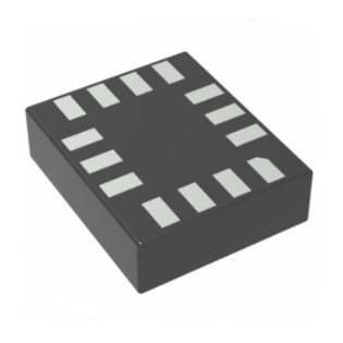


 工商网监
湘ICP备2023018690号
工商网监
湘ICP备2023018690号
