+
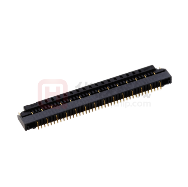
0.4/0.5mm Pitch 1.5mm Height High Speed Transmission (5 Gbps) FPC Connectors
FH55/FH55M Series
Dimensions : 40 pos
23.
4m
m(
4mm (depth)
FH
55)
/19
.3m
m(
FH
55M
)
Fig.1
Capable of transmitting high-speed differential
signals by arranging signal contacts (S) and ground
+
contacts (G) in the sequence of GSSG. (5 Gbps)
(The GSSG layout utilizes differential signals, but
the contacts can also be designated for other uses
other than differential signals.)
2. Impedance Matched-Contact Design
The signal contacts were designed with impedance
control in mind and to realize superior high-speed
transmission feature.(Fig.2)
FH55 differential impedance
50 ps rise time (20-80%)
&'%
&&%
.% &*P°R
8DCC:8IDG
&%%
O��D]b�
■Features
+
1. High-Speed Transmission(5 Gbps) FPC Connectors
;E8
.%P°R
.%
-%
.%"&*P°R
,%
+% �
%#+ %#, %#- %#.
&
&#& &#' &#( &#) &#* &#+
I^bZ��ch�
Fig.2
3. Fully Enclosed Molded Structure (Over molding Structure)
Board space under the connector can be utilized in
patterning since the bottom of the connector is
covered with resin and enhances PCB flexibility.
4. Flip-Lock System Provides Reliability and FPC Security
The Flip-lock (one-touch rotational lock) ZIF
structure allows for a reliable and simple to secure
FPC connection operation. Utilizing a clear clicking
feeling at the time of locking prevents an
incomplete lock.
FH55 eye diagram (5 Gbps)
0.6
Eye_Probe_Rx.Density
Apr.1.2022 Copyright 2022 HIROSE ELECTRIC CO., LTD. All Rights Reserved.
1.5mm
0.2
0.0
-0.2
-0.4
-0.6
0
5. Easy FPC insertion
The FPC guiding system utilizes guide tabs that
enable a temporary hold while FPC is inserted and
accurately determines mating location all while
ensuring a consistent connection.
0.4
50
100
150
200
250
300
350
400
Fig.3
time, psec
FPC Insertion
Actuator open
6. Compatible with 0.3mm Thick FPC
This connector utilizes 0.3mm thick FPC, which is
the standard thickness of a 0.5mm pitch connector
(Appropriate stiffness with reinforcing board
prevents FPC deformation, preventing troubles at
times of insertion and mating).
FPC
Fig.4
7. Automatic Mounting Option Available
Emboss packaging makes automatic mounting
possible (5,000 pcs/reel).
Locked
8. Halogen-free
Chlorine and bromine are not used in amounts that
exceed the standard values in these connectors.
* Defined according to IEC 61249-2-21
Br : 900ppm or below ; CI : 900pm or below ; Br + Cl :
1,500ppm or below
In cases where the application will demand a high level of reliability, such as automotive,
please contact a company representative for further information.
Fig.5
2015.12 ③
1
�+
FH55/FH55M Series●0.4/0.5mm Pitch 1.5mm Height High Speed Transmission (5 Gbps) FPC Connectors
■Product Specifications
Ratings
Curren
ratingt
0.5A (0.5mm pitch products)(Note 1) Operating
Storage temperature -10 to +50°C
-55 to +85°C (Note 2)
0.4A (0.4mm pitch products)(Note 1) temperature range
range
(Note 3)
Voltage AC 50V rms (0.5mm pitch products) Operating
rating
AC 40V rms (0.4mm pitch products) humidity range
Suitable FPC/FFC
contact specifications
Storage humidity
range
RH 90% or less
(no condensation)
t = 0.3 ± 0.03 gold-plated
Items
Apr.1.2022 Copyright 2022 HIROSE ELECTRIC CO., LTD. All Rights Reserved.
RH 90% or less (no
condensation)
Specifications
Conditions
1.Insulation Resistance
500Mø min
Measured at DC 100V
2.Withstanding Voltage
No flashover or breakdown
AC 150Vrms applied for 1 minute
3.Contact Resistance
100mø max
* Including FPC conductor resistance
Measured at 1mA
4.Repeat Performance
100mø max
No breakage, cracking, or loosening to parts
20 times
5.Vibration Resistance
No electric outage of 1µ or greater
Contact resistance : 100mø max
No breakage, cracking, or loosening to parts
10 cycles in each of three directions at frequency
10-55 Hz, half amplitude 0.75mm
6.Shock Resistance
No electric outage of 1µ or greater
Contact resistance : 100mø max
No breakage, cracking, or loosening to parts
Acceleration of 981m/s2 ; duration 6ms, sine halfwave, 3 cycles in each of the 3 axes each in both
directions
Contact Resistance : 100mø max
7.Humidity Resistance in
Insulation Resistance : 50Mø min
Steady State
No breakage, cracking, or loosening to parts
96 hours at temperature 40°C and humidity 90-95%
8.Temperature Cycle
Contact Resistance : 100mø max
Insulation Resistance : 50Mø min
No breakage, cracking, or loosening to parts
Temperature : -55°C ➝ +15°C to +35°C ➝ +85°C ➝ + 15° to +35°C
Time : 30 ➝ 2 to 3 ➝ 30 ➝ 2 to 3 minutes
5 cycles with the above conditions
9.Solder Heat
Resistance
No marked instability in contacts, or
appearance of deformation.
1) Reflow : Peak temperature MAX 250°C, 230°C or
greater for 60 seconds
2) Soldering iron : 350±10°C for 5 seconds
Note 1 : Use at 70% of the current rating when all pins are energized with current rating.
Note 2 : Temperature rise at the time of electrification is included.
Note 3 : The term “storage” refers to the long-term storage condition of unused products before board mounting. The operating
temperature and humidity ranges apply to non-energized state after board mounting.
■Materials / Finish
Part
Materials
Color/finish
Remarks
Gray
Insulator
LCP
Contact
Phosphor bronze
Gold-plating
Brass
Pure tin reflow plating
Metal Parts
UL94V-0
Black
−ーーー
■Product Number Structure
FH 55 M − 40S − 0.5 SH
❶
❷
❸
❹
❶ Series name : FH
❺
❻
❹ Number of contacts : 10 to 61 positions (0.5mm pitch products)
19 to 79 positions (0.4mm pitch products)
❷ Series No. : 55
❸ No symbol : 0.5mm pitch products
M : 0.4mm pitch products
❺ Contact pitch : 0.5mm or 0.4mm
❻ Contact Form
SH : SMT horizontal mounting type
2
�+
FH55/FH55M Series●0.4/0.5mm Pitch 1.5mm Height High Speed Transmission (5 Gbps) FPC Connectors
■Connector dimensional drawing
●0.5mm/0.4mm pitch products
A
B
R
Pin No.: 1
S:SIGNAL CONTACT
(0.12)
(3.8)
G:GROUND CONTACT
A**
HRS mark
Number of contacts
Cavity No
°)
15
1.1
(0.15)
(2.7)
(1
1.5
Apr.1.2022 Copyright 2022 HIROSE ELECTRIC CO., LTD. All Rights Reserved.
Polarity mark
0.3
(C: FPC insertion area dimension)
4
D
(4.2)
Notes : 1. The dimensions in parentheses ( ) are reference values.
2. The lead co-planarity of connector and reinforcing metal part is MAX 0.1mm.
3. This product is emboss-packaged. See the package specification diagram for details.
4. Dimensions may be changed for sink mark prevention due to improvement, etc.
5. Black dots, etc. may occur in mold resin but do not create a quality problem.
6. This product is the halogen-free product. (Br content rate: 900 ppm or less ; CI content rate : 900ppm
or less; Br + CI total content rate : 1,500ppm or less)
7. See the table below for available pin arrangements.
S : SIGNAL CONTACT G : GROUND CONTACT
* Pins are arranged in the sequence of GSSG to manage high-speed differential signals ; however, all
contacts can be used as signals for normal signals other than high-speed signals. Please contact
our sales representative for any questions.
Pin No.
1 2 3 4 5 6 7 8 9 10 11 12 13 14 15 16 17 18 19 20 21 22 23 24 25 26 27 28 29 30 31 32 33 34 35
Pin assignment G S S G S S G S S G S S G S S G S S G S S G S S G S S G S S G S S G S
36 37 38 39 40 41 42 43 44 45 46 47 48 49 50 51 52 53 54 55 56 57 58 59 60 61 62 63 64 65 66 67 68 69 70
S G S S G S S G S S G S S G S S G S S G S S G S S G S S G S S G S S G
71 72 73 74 75 76 77 78 79
S S G S S G S S G
Unit : mm
Part No.
HRS No.
No. of contacts No. of signal contacts No. of ground contacts
A
B
C
D
4
8.4
4.5
5.57
7.59
14
8
14.4
10.5
11.57 13.59
20
11
18.9
15
16.07 18.09
40
26
14
23.4
19.5
20.57 22.59
Under planning
49
32
17
27.9
24
25.07 27.09
FH55-61S-0.5SH
Under planning
61
40
21
33.9
30
31.07 33.09
FH55M-19S-0.4SH
Under planning
19
12
7
10.9
7.2
8.07
FH55M-31S-0.4SH
580-3711-0 00
31
20
11
15.7
12
12.87 14.89
FH55-10S-0.5SH
Under planning
10
6
FH55-22S-0.5SH
580-3707-7 00
22
FH55-31S-0.5SH
580-3704-9 00
31
FH55-40S-0.5SH
580-3700-8 00
FH55-49S-0.5SH
R
0.5
10.09
FH55M-40S-0.4SH
580-3706-4 00
40
26
14
19.3
15.6
16.47 18.49
FH55M-49S-0.4SH
Under planning
49
32
17
22.9
19.2
20.07 22.09
FH55M-61S-0.4SH
Under planning
61
40
21
27.7
24
24.87 26.89
FH55M-79S-0.4SH
Under planning
79
52
27
34.9
31.2
32.07 34.09
0.4
The products above without a HRS No. are currently under planning. Please contact our sales representative for questions concerning the number of contacts.
3
�+
FH55/FH55M Series●0.4/0.5mm Pitch 1.5mm Height High Speed Transmission (5 Gbps) FPC Connectors
Recommended PCB mounting pattern
●FH55M Series
E± 0.05
0.7 ± 0.03
B
0.4
PIN No.1
0.22 ± 0.02
Connector image:underside
E± 0.05
0.7 ± 0.03
0.7 ± 0.03
Q
×NUMBER OF CONTACTS
0.04 Q
( 0.2 )
0.65 ± 0.03
Connector image:underside
4.3 ± 0.05
( 0.2 )
PIN No.1
Q
×NUMBER OF CONTACTS 0.3 ± 0.03
0.1 Q
1.5 ± 0.03
4.3 ± 0.05
B
0.5
1.5 ± 0.03
0.65 ± 0.03
●FH55 Series
0.7 ± 0.03
( A)
( A )
Recommended Stencil pattern
●FH55 Series
●FH55M Series
0.7 ± 0.03
0.6 ± 0.01
×NUMBER OF CONTACTS
0.1 S
0.25 ± 0.03
PCB mounting pattern image
0.4
S
×NUMBER OF CONTACTS
0.02 S
PIN No.1
0.2 ± 0.01
PCB mounting pattern image
E± 0.02
0.7 ± 0.01
0.7 ± 0.03
E± 0.05
4.3 ± 0.02
PIN No.1
RECOMMENDED STENCIL THICKNESS: t=0.10
B
S
1.5 ± 0.01
0.5
4.3 ± 0.05
1.5 ± 0.03
0.65 ± 0.03
Apr.1.2022 Copyright 2022 HIROSE ELECTRIC CO., LTD. All Rights Reserved.
RECOMMENDED STENCIL THICKNESS: t=0.10
B
0.7 ± 0.01
( A )
( A )
Recommended FPC dimensional drawing
F±0.1
G±0.05
B±0.03
W±0.03
2×R0.2±0.1
2.5±0.3
2×R0.2±0.1
0.3±0.03
2×R0.2±0.1
(1MIN)
2×R0.2±0.1
(2.9)
R±0.03
3.5 MIN(Stiffener)
2×R0.2±0.1
R±0.07
0.6±0.05
0.35±0.05
1.5±0.05
R±0.07
Ground copper foil
Unit : mm
Part No.
HRS No.
No. of contacts No. of signal contacts No. of ground contacts
4
E
F
G
7
6.65
5.5
FH55-10S-0.5SH
Under planning
10
6
FH55-22S-0.5SH
580-3707-7 00
22
14
8
13
12.65
11.5
FH55-31S-0.5SH
580-3704-9 00
31
20
11
17.5
17.15
16
FH55-40S-0.5SH
580-3700-8 00
40
26
14
22
21.65
20.5
FH55-49S-0.5SH
Under planning
49
32
17
26.5
26.15
25
FH55-61S-0.5SH
Under planning
61
40
21
32.5
32.15
31
FH55M-19S-0.4SH
Under planning
19
12
7
9.5
9.15
8
FH55M-31S-0.4SH
580-3711-0 00
31
20
11
14.3
13.95
12.8
FH55M-40S-0.4SH
580-3706-4 00
40
26
14
17.9
17.55
16.4
FH55M-49S-0.4SH
Under planning
49
32
17
21.5
21.15
20
FH55M-61S-0.4SH
Under planning
61
40
21
26.3
25.95
24.8
FH55M-79S-0.4SH
Under planning
79
52
27
33.5
33.15
32
R
W
0.5
0.37
0.4
0.27
The products above without a HRS No. are currently under planning. Please contact our sales representative for questions concerning the number of contacts.
4
�+
FH55/FH55M Series●0.4/0.5mm Pitch 1.5mm Height High Speed Transmission (5 Gbps) FPC Connectors
FH55/FH55M Series FPC Material Constitution (Recommended Specifications)
①Cover lay film
③Surface finish (Nickel base + Gold plating)
②Cover adhesive
④Copper plating (Through-hole copper)
⑤Pattern copper foil
⑥Base adhesive (Thermosetting adhesive)
⑨Ground copper foil
⑦Base film
⑧Base adhesive (Thermosetting adhesive)
⑩Copper plating (Through-hole copper)
⑪Cover adhesive (Thermosetting adhesive)
⑫Cover lay film
⑬Reinforcement material adhesive (Thermosetting adhesive)
Notes 1 : The FPC material
Material Thickness (µm)
Names of Materials
LCP
PI
PI
2-layer CCL 2-layer CCL 3-layer CCL
①Cover lay film
constitution is a
2
reference example.
12.5
12.5
12.5
②Cover adhesive
28
28
28
③Surface treatment (nickel base + gold plating)
(6)
(6)
(6)
④Copper plating (through-hole copper)
15
15
15
mating area 0.3±0.03
⑤Pattern copper foil
9
18
18
mm by referring
⑥Base adhesive
-
-
16
to this material
constitution.
2
⑦Base film
Please make the
thickness of FPC
50
25
25
⑧Base adhesive
-
-
16
⑨Ground copper foil
9
18
18
⑩Copper plating (through-hole copper)
15
15
15
example of the base
⑪Cover adhesive
28
28
28
film material. LCP
12.5
12.5
12.5
refers to liquid crystal
50
50
30
polymer, and PI for
125
150
125
295.5
304.5
291.5
⑫Cover lay film
⑬Reinforcement material adhesive (Thermosetting adhesive)
⑭Stiffener film
Total (Mating Area Thickness: Total of ③∼⑧ and ⑪∼⑭)
2
It is a reference
polyimide.
Temperature Profile
MAX 250℃
250
230℃
200
Temperature (C°)
Apr.1.2022 Copyright 2022 HIROSE ELECTRIC CO., LTD. All Rights Reserved.
⑭Stiffener film
200℃
150
150℃
100
50
25℃
(60 seconds)
0
90-120 seconds
Preheating time
Start
Time (second)
(60 seconds)
Soldering time
Applicable Conditions
Reflow System : Far-infrared, hot-air reflow
Reflow chamber atmosphere : Air
Solder
: Paste type Sn/3.0Ag/0.5 Cu
(M705-221CM5-42-10.5 ;
Senju Metal Industry Co., Ltd.)
Test Board
: Board material and size
Glass epoxy 30 x 60 x 1.0mm
Land dimensions
Contact area: 0.3 x 0.65
Metal part area: 0.7 x 1.5mm
Metal Mask
: Thickness 0.1 mm
Aperture Dimension
Contact area 0.25 x 0.65
Metal part area 0.7 x 1.5mm
The temperature profile shown above is based on
the above applicable conditions.
Due to the changing conditions such as solder paste
types, manufacturers, board size and other
soldering materials, please check to ensure the
proper soldering conditions before use.
5
�+
FH55/FH55M Series●0.4/0.5mm Pitch 1.5mm Height High Speed Transmission (5 Gbps) FPC Connectors
Package Specifications
●Emboss carrier tape dimensional drawing
2±0.1
4±0.1
8±0.1
.1
+0 0
.5
(4.05)
(4.95)
J±0.1
( 0.3)
K±0.1
L±0.3
(1.5: Automatic mounting vacuum pickup area)
1.7 +0.15
0
Apr.1.2022 Copyright 2022 HIROSE ELECTRIC CO., LTD. All Rights Reserved.
(H)
Ø
(0.3 )
(H)
.1
+00
1.5
(1.9 )
( 1.9)
L±0.3
8±0.1
1.75±0.1
2±0.1
J±0.1
4±0.1
Ø1
1.75±0.1
(Tape width: 32mm or more)
(Tape width: 24mm or less)
Pulling direction
1.5
(1.5: Automatic mounting vacuum pickup area)
(4.05)
+0.1
0
(4.95)
Pulling direction
●Reel state dimensional drawing
(Ø380)
(Ø80)
(M: Reel outer width)
(N: Reel inner width)
3)
(Ø1
Terminal Area
Empty Area
Mounting Area
Emboss carrier tape
(20 pockets or more)
Leader Area (400mm or more)
Empty Area
Top cover tape
(13 pockets or more)
Unit : mm
H
J
K
FH55-10S-0.5SH
Part No.
Under planning
HRS No.
No. of contacts No. of signal contacts No. of ground contacts
10
6
4
8.6
11.5
―
FH55-22S-0.5SH
580-3707-7 00
22
14
8
14.6 11.5
―
FH55-31S-0.5SH
580-3704-9 00
31
20
11
19.1 14.2 28.4
L
M
N
24
29.4 25.4
32
37.4 33.4
FH55-40S-0.5SH
580-3700-8 00
40
26
14
23.6
FH55-49S-0.5SH
Under planning
49
32
17
28.1
20.2 40.4
44
49.4 45.4
FH55-61S-0.5SH
Under planning
61
40
21
34.1 26.2 52.4
56
61.4 57.4
FH55M-19S-0.4SH
Under planning
19
12
7
11.1 11.5
24
29.4 25.4
FH55M-31S-0.4SH
580-3711-0 00
31
20
11
15.9 14.2 28.4
32
37.4 33.4
FH55M-40S-0.4SH
580-3706-4 00
40
26
14
19.5
FH55M-49S-0.4SH
Under planning
49
32
17
23.1 20.2 40.4
44
49.4 45.4
FH55M-61S-0.4SH
Under planning
61
40
21
27.9
FH55M-79S-0.4SH
Under planning
79
52
27
35.1 26.2 52.4
56
61.4 57.4
―
The products above without a HRS No. are currently under planning. Please contact our sales representative for questions concerning the number of contacts.
6
�+
FH55/FH55M Series●0.4/0.5mm Pitch 1.5mm Height High Speed Transmission (5 Gbps) FPC Connectors
Operation of Connector and Precautions
Operation
1. FPC insertion method
❷ Insert FPC with its conductor side facing down.
There is an FPC position guiding tab. Insert FPC at an angle of approximately 12° against the PCB surface
and vertical to the connector. Make sure to insert it completely.
(12°
)
FPC Side-Catch guide
Vertical to connector
❸ Operate the actuator in a rotational manner and press it down. When FPC is half inserted or insertion is
significantly misaligned, remove the FPC according to the extraction method of 2-❶ and operate it again
from 1-❷. Fix the connector at the time of locking.
2. FPC Extraction Method
❶ Operate the actuator upward in a rotational manner by flipping it up and extract FPC after releasing the lock.
As there is the FPC position guiding tab, extract the FPC at an angle of approx. 12° against the PCB surface.
(12°
)
Apr.1.2022 Copyright 2022 HIROSE ELECTRIC CO., LTD. All Rights Reserved.
❶ Operate the actuator as it rotates upward and open it. The actuator can be easily operated by flipping it up with
a fingernail.
FPC Side-Catch guide
7
�+
FH55/FH55M Series●0.4/0.5mm Pitch 1.5mm Height High Speed Transmission (5 Gbps) FPC Connectors
Precautions on Use
As this connector requires careful handling, please check the following points before use. Of
note, values described in the precautions are different from the product specification values.
[Precautions at Time of Mounting on PCB]
◆PCB Warpage
Please minimize the PCB warpage amount as much as possible. Although the coplanarity of this connector is
0.1mm or less, mounting failure may occur with an excessive amount of warpage.
◆Load to Connector
Do not to place an excessive external load (1N or less) on the connector before mounting or when removing the
emboss package from the reel or when absorbing connectors from the emboss package. Not following these
precautions may result in connector breakage. **Do not insert FPC or operate connector before mounting.**
[Precautions when handling PCB after mounting]
Apr.1.2022 Copyright 2022 HIROSE ELECTRIC CO., LTD. All Rights Reserved.
◆Load to PCB
Please do not place load to the PCB in the assembly process when conducting the following, as it may result in
connector breakage.
•Separating the large PCB into individual PCBs
•Attaching PCB with screws
◆Board Bending
For a board width of 100mm, do not bend the board more than a MAX of 0.5mm (See the diagram below).
Bending the board more than 0.5mm may impose that load to the connector and result in breakage.
1MAX
100
Connector
PCB
1MAX
Connector
PCB
100
[Precautions when Inserting or Mating the FPC]
Please pay attention to the following points at the time of FPC insertion and mating.
◆❶ Actuator Operation
When opening the actuator from it’s initial state (FPC non-insertion state), please pay attention not to place an
excessive amount of force on the actuator. **Please see the diagram below to prevent deformity of the actuator
through finger nail damage.
Deformation of Contact Tip
Deformation of Contact Upper Arm
❷ As the actuator rotates centering around the shaft as shown in the diagram below, operate it in a
rotational manner.
Rotation axis
8
�+
FH55/FH55M Series●0.4/0.5mm Pitch 1.5mm Height High Speed Transmission (5 Gbps) FPC Connectors
Precautions on Use
❸ As the actuator structurally does not open more than 115°, please do not apply force to rotate it further
toward back. It may result in disengagement or breakage of the actuator.
5°
❹ Operate the actuator in its center area. When closing the actuator while FPC is inserted, operating it at its
edge may result in breakage of the actuator or incomplete mating.
❺ Do not lift the actuator by clipping it or pick it up as shown in the diagrams on the right, as it may result
in breakage [Do not perform operations other than the rotational movement described in ❹].
SContact Point Direction
The contact point on this connector is on the bottom; therefore insert the FPC with the conductor exposed surface
facing down.
SFPC Insertion
❶ There is a FPC position guiding tab. Make sure to completely insert FPC at an angle of approx. 12°
against the PCB surface and vertically to the connector. If FPC is inserted at a slant angle, it may result
in short circuit failure due to pitch misalignment or contact deformation with the FPC corner getting
caught at contacts.
(12°
)
Apr.1.2022 Copyright 2022 HIROSE ELECTRIC CO., LTD. All Rights Reserved.
11
FPC Side-Catch
Contact deformation
9
�+
FH55/FH55M Series●0.4/0.5mm Pitch 1.5mm Height High Speed Transmission (5 Gbps) FPC Connectors
Precautions on Use
❷ Please do not insert FPC at a markedly slant angle from above. If it is inserted at a markedly slant angle from
above in the FPC insertion process as shown in the diagram below, FPC may bend and break the pattern, or
insufficient insertion of FPC may result in conduction failure.
FPC pattern lead breakage
Apr.1.2022 Copyright 2022 HIROSE ELECTRIC CO., LTD. All Rights Reserved.
Contact deformation
* In order to prevent slant insertion of FPC, make sure to secure sufficient space for FPC insertion at the time
of layout designing. Insertion will become difficult if FPC is too short, therefore, please design appropriate
part layout.
* Please confirm details of the flexion and wire breakage of FPC with your FPC manufacturer.
❸ After FPC insertion, make sure that the FPC position guiding tab is not on top of the FPC position guide on
both sides of the connector. Contact failure may occur if the actuator is locked while the FPC position guiding
tab is still on top of the FPC position guide.
FPC Side-Catch
FPC Side-Catch guide
(Correct insertion)
(Laid on both guides)
(Laid on one guide)
SLock State Confirmation
At the time of locking, make sure that the actuator is parallel to the PCB surface. However, when the actuator
gets close to 0°, make sure you use the appropriate amount of force as the use of excessive force, may result
in contact deformation (1N or less).
[Precautions when Routing FPC after FPC Insertion]
SAbout the load on the FPC
After the FPC has been inserted, ensure that no load will be applied to the FPC. Bending the FPC at a position
near the connector may cause contact failure or FPC lead breakage/damage. In particular, fix the FPC when
load is continuously applied to it. Do not bend the FPC sharply near the FPC insertion slot at the time of
routing the FPC.
10
�+
FH55/FH55M Series●0.4/0.5mm Pitch 1.5mm Height High Speed Transmission (5 Gbps) FPC Connectors
Precautions on Use
[Precautions when Removing FPC]
SOperate the actuator at the center area when releasing it
If you operate the actuator at its edge when releasing the lock while the FPC is inserted, it may result in
actuator breakage.
(12°
)
Apr.1.2022 Copyright 2022 HIROSE ELECTRIC CO., LTD. All Rights Reserved.
SExtracting the FPC while the actuator is unlocked.
Since these connectors have FPC position guiding tabs, extract the FPC at an angle of 12° against the PCB.
FPC Side-catch
[Other Precautions]
SHand Soldering Precautions
When hand soldering for repair, etc.:
❶ Do not perform reflow or hand soldering with the FPC inserted in the connector.
❷ Do not apply excessive heat and make sure that the soldering iron does not touch anywhere other than the
connector lead. It may result in connector deformation or melting.
❸ Do not supply excessive solder (flux).
If an excessive amount of solder (flux) is supplied to the contact, solder or flux may adhere to the contact
points or the shaft of the actuator and can result in contact failure or rotational performance failure of the
actuator
11
�+
Apr.1.2022 Copyright 2022 HIROSE ELECTRIC CO., LTD. All Rights Reserved.
FH55/FH55M Series●0.4/0.5mm Pitch 1.5mm Height High Speed Transmission (5 Gbps) FPC Connectors
USA:
HIROSE ELECTRIC (U.S.A.), INC. HEADQUARTERS
2300 Warrenville Road, Suite 150,
Downers Grove, IL 60515
Phone : +1-630-282-6700
http://www.hirose.com/us/
USA:
HIROSE ELECTRIC (U.S.A.), INC. SAN JOSE OFFICE
2841 Junction Ave, Suite 200
San Jose, CA. 95134
Phone : +1-408-253-9640
Fax : +1-408-253-9641
http://www.hirose.com/us/
USA:
HIROSE ELECTRIC (U.S.A.), INC. DETROIT OFFICE (AUTOMOTIVE)
17197 N. Laurel Park Drive, Suite 253,
Livonia, MI 48152
Phone : +1-734-542-9963
Fax : +1-734-542-9964
http://www.hirose.com/us/
THE NETHERLANDS:
HIROSE ELECTRIC EUROPE B.V.
Hogehillweg #8 1101 CC Amsterdam Z-O
Phone : +31-20-6557460
Fax : +31-20-6557469
http://www.hirose.com/eu/
GERMANY:
HIROSE ELECTRIC EUROPE B.V. GERMAN BRANCH
Herzog-Carl-Strasse 4 D-73760 Ostfildern
(Scharnhauser Park)
Phone : +49-711-4560-02-1
Fax : +49-711-4560-02-299
http://www.hirose.com/eu/
GERMANY:
HIROSE ELECTRIC EUROPE B.V. NUERNBERG OFFICE
Muggenhofer Str. 136 90429 Nuernberg
Phone : +49-911 32 68 89 63
Fax : +49-911 32 68 89 69
http://www.hirose.com/eu/
GERMANY:
HIROSE ELECTRIC EUROPE B.V. HANOVER OFFICE
Bayernstr. 3, Haus C 30855 Langenhagen, Germany
Phone : +49-511 97 82 61 30
Fax : +49-511 97 82 61 35
http://www.hirose.com/eu/
FRANCE:
HIROSE ELECTRIC EUROPE B.V. PARIS OFFICE
Regus La Garenne Colombes,Place de La Belgique,
71 Boulevard National La Garenne Colombes, 92250, France
Phone : +33 (0) 1 7082 3170
Fax : +33 (1) 7082 3101
http://www.hirose.com/eu/
UNITED KINGDOM:
HIROSE ELECTRIC EUROPE BV (UK BRANCH)
4 Newton Court, Kelvin Drive, Knowlhill,
Milton Keynes, MK5 8NH
Phone : +44-1908 202050
Fax : +44-1908 202058
http://www.hirose.com/eu/
CHINA:
HIROSE ELECTRIC (SHANGHAI) CO., LTD.
1601, Henderson Metropolitan, NO.300, East Nanjing
Road, Huangpu District, Shanghai, China 200001
Phone : +86-21-6391-3355
Fax : +86-21-6391-3335
http://www.hirose.com/cn/
CHINA:
HIROSE ELECTRIC (SHANGHAI) CO.,LTD. BEIJING BRANCH
A1001, Ocean International Center, Building 56# East 4th
Ring Middle Road, ChaoYang District, Beijing, 100025
Phone : +86-10-5165-9332
Fax : +86-10-5908-1381
http://www.hirose.com/cn/
CHINA:
HIROSE ELECTRIC TECHNOLOGIES (SHENZHEN) CO., LTD.
Room 09-13, 19/F, Office Tower Shun Hing Square, Di Wang Commercial Centre,
5002 Shen Nan Dong Road, Shenzhen City, Guangdong Province, 518008
Phone : +86-755-8207-0851
Fax : +86-755-8207-0873
http://www.hirose.com/cn/
HONG KONG:
HIROSE ELECTRIC HONGKONG TRADING CO., LTD.
Room 1001, West Wing, Tsim Sha Tsui Centre, 66
Mody Road, Tsim Sha Tsui East, Kowloon, Hong Kong
Phone : +852-2803-5338
Fax : +852-2591-6560
http://www.hirose.com/hk/
TAIWAN:
HIROSE ELECTRIC TAIWAN CO., LTD.
103 8F, No.87, Zhengzhou Rd., Taipei
Phone : +886-2-2555-7377
Fax : +886-2-2555-7350
http://www.hirose.com/tw/
KOREA:
HIROSE KOREA CO., LTD.
250, Huimanggongwon-ro, Siheung-si,
Gyeonggi-do, Korea, 429-849
Phone : +82-31-496-7000,7124
Fax : +82-31-496-7100
http://www.hirose.co.kr/
SINGAPORE:
INDIA:
HIROSE ELECTRIC SINGAPORE PTE. LTD. DELHI LIAISON OFFICE
HIROSE ELECTRIC SINGAPORE PTE. LTD.
10 Anson Road #26-16, International Plaza Office NO.519, Regus-Green Boulevard, Level5, Tower C,
Sec62, Plot B-9A, Block B, Noida, 201301, Uttar Pradesh, India
079903, Singapore
Phone : +91-12-660-8018
Phone : +65-6324-6113
Fax : +91-120-4804949
Fax : +65-6324-6123
http://www.hirose.com/sg/
http://www.hirose.com/sg/
MALAYSIA:
HIROSE ELECTRIC MALAYSIA PTE. LTD.
1-10-07, Suntech @ Penang Cybercity (1164),Lintang
Mayang Pasir 3,11950, Bayan Baru, Penang, Malaysia.
Phone : +604-619-2564
Fax : +604-619-2574
http://www.hirose.com/sg/
®
12
INDIA:
HIROSE ELECTRIC SINGAPORE PTE. LTD. BANGALORE LIAISON OFFICE
Unit No-403, 4th Floor, No-84, Barton Centre, Mahatma
Gandhi (MG) Road, Bangalore 560 001, Karnataka, India
Phone : +91-80-4120 1907
Fax : +91-80-4120 9908
http://www.hirose.com/sg/
THAILAND:
BANGKOK OFFICE (REPRESENTATIVE OFFICE)
Unit 4703, 47th FL., 1 Empire Tower, South Sathorn
Road, Yannawa, Sathorn, Bangkok 10120 Thailand
Phone : +66-2-686-1255
Fax : +66-2-686-3433
http://www.hirose.com/sg/
2-6-3,Nakagawa Chuoh,Tsuzuki-Ku,Yokohama-Shi 224-8540,JAPAN
TEL: +81-45-620-3526 Fax: +81-45-591-3726
http://www.hirose.com
http://www.hirose-connectors.com
The characteristics and the specifications contained herein are for reference purpose. Please refer to the latest customer drawings prior to use.
The contents of this catalog are current as of date of 12/2015. Contents are subject to change without notice for the purpose of improvements.
�


 工商网监
湘ICP备2023018690号
工商网监
湘ICP备2023018690号
