12 / 2020
ver. 1.26
INSTALLATION GUIDE
GENERAL INFORMATION ABOUT ASSEMBLING LEDIL PRODUCTS
�LEDiL Installation Guide
READ THE FOLLOWING INSTRUCTIONS BEFORE USING
LEDIL PRODUCTS TO ENSURE RELIABLE ASSEMBLY.
CONTENTS
MATERIALS
3
INSTALLATION
23
PMMA & PC
3
Tape
23
Silicone (as a lens material)
3
Screw
24
Heat durability of different materials
4
Glue
25
6
Potting
25
Glues / adhesives / potting / thread lock
6
Press-fit
25
Chemical resistance
7
Holder
25
Silicone
7
Profiles
26
PMMA
7
PCB design
27
PC
8
LED assembly
27
28
CHEMICALS
STRESS CRACKING
15
LED chip positions
UV-RESISTANCE
16
LED compatibility tolerances
Plexiglas guarantee
16
Distance between lenses
28
Silicone
16
Sealing and ingress protection of LEDiL optics
29
PC
16
THERMAL MANAGEMENT
2
30
FIRE RATING
17
Heat sink machining
31
Fire ratings
17
Thermal interface materials
31
Hot Wire Ignition (HWI)
18
Thermal measurements
32
High Amp Arc Ignition (HAI)
18
Outdoor suitability
18
Vacuum Evaporation PVD
34
LEDiL materials fire rating
19
HMDS
34
METAL COATING
33
TENSILE STRENGTH
20
STORAGE
35
TOLERANCES
21
LINKS TO USEFUL INFORMATION
35
The information contained herein is the property of LEDiL Oy, Joensuunkatu 13, FI-24100 SALO, Finland and is subject to change without notice. Please visit
www.ledil.com for additional information, such as the latest photometric files, 3D mechanical models, and application notes relating to handling, gluing and taping.
2
�LEDiL Installation Guide
MATERIALS
PMMA & PC (TRANSPARENT PLASTIC POLYMERS IN OPTICS)
PMMA:
• Rigid and hard
• Average chemical resistance
• Good UV-resistance (naturally UV-stable
technology)
• Good light transmission
PC:
• Very tough with excellent physical properties
• Good chemical resistance
• Good heat resistance
• Average UV-resistance (LEDiL uses
UV-stabilized clear PC-grade)
In general, PMMA is harder and more fragile than PC, which has greater resistance to impact and
heat. LEDiL uses many different types of PC in its products and the information given here is only valid
for Makrolon 2407. Although other types of PC offer similar properties their performance should be
verified separately.
Transparent polymers can reflect, absorb and refract visible light. Absorption causes the temperature
to increase in a lens and this should be taken into consideration during heat simulations. In general,
PMMA lenses have higher light transmission rates meaning less light is absorbed. PC on the other
hand has better heat resistance, but thicker parts can absorb more light resulting in increased internal
temperatures. LEDiL uses UV-stabilized clear PC for optics and all materials are f1-rated (UL746Cstandard is suitable for outdoor applications and meets UV and water exposure demands).
SILICONE (AS A LENS MATERIAL)
Silicone has excellent optical properties, great
impact strength, durability and high thermal
stability. Silicone’s elasticity allows complex
optical and functional forms and low viscosity
makes microstructural design possible. Silicone
has high stability in ultraviolet light and ozone
and can be used with UV LEDs where even UV
stabilized plastics are unsuitable.
Silicone:
• Excellent optical properties with even
better efficiency than glass
• Elasticity allows complex optical and
functional forms
• High thermal and UV stability
• Great impact strength
• Lightweight design (lighter than glass)
As part of our continuous research and improvement processes LEDiL reserves the right of changing material grades
without further notice to ensure best possible quality and availability of our products.
The information contained herein is the property of LEDiL Oy, Joensuunkatu 13, FI-24100 SALO, Finland and is subject to change without notice. Please visit
www.ledil.com for additional information, such as the latest photometric files, 3D mechanical models, and application notes relating to handling, gluing and taping.
3
�LEDiL Installation Guide
HEAT DURABILITY OF DIFFERENT MATERIALS
LED lighting consumes much less power compared to other light sources such as bulbs, fluorescent
or energy saving lamps. These tiny light sources are at the focal point of worldwide continuous
improvement constantly pushing the edge of heat resistance and luminous output.
If in the early days of LED lighting the power consumption produced around 80°C or 90°C of heat,
today the extremely large COBs can produce around 150°C. This direction has led to a situation
where luminaire materials need to handle and dispose of more and more heat to ensure safe operation.
Sources of heat
As a general rule 1/3 of an LED’s power consumption is turned into visible light and 2/3 into heat.
There are three sources that produce heat in LED lighting: conduction, convection and radiation. All of
these are extremely important when a new luminaire design is made but there are also other things to
consider regarding heat generation.
Some materials absorb more light than others. This means that an optic’s efficiency has a direct link
to how hot the lens will get. All sorts of dirt, dust and grease on the optical surface block some of the
light rays generating more heat inside the luminaire. During the product lifetime both of these effects
tend to increase and therefore speed up the aging process. Every luminaire element and component
that stops or reflects some of the light such as protective glass and shades, may also increase heat
inside the luminaire and therefore speed up the aging process.
Careful consideration should be given to all of these areas when designing a luminaire to ensure a
safe and long product lifetime. LEDiL products are designed and manufactured to meet high efficiency
values to help extend the product lifetime.
Choosing the right material
On the following page you can find a list of materials and recommended maximum service temperatures.
Please note that because of the complex nature and numerous variables involved in luminaire design
and manufacturing that affect the final product heat control, LEDiL cannot take responsibility for third
party solutions and designs we can’t control. It is always the customer’s responsibility to determine
and verify there is sufficient cooling and maintenance in the final product and its components.
The information contained herein is the property of LEDiL Oy, Joensuunkatu 13, FI-24100 SALO, Finland and is subject to change without notice. Please visit
www.ledil.com for additional information, such as the latest photometric files, 3D mechanical models, and application notes relating to handling, gluing and taping.
4
�LEDiL Installation Guide
MAX RECOMMENDED
SERVICE TEMPERATURE (°C)
SPECIMEN THICKNESS (MM)
(UL SPECIFICATION)
70
1.5 - 3
130
> 1.5
70
1.5
HRPC2) (ANGELA, ANGELINA, BARBARA, MIRELLA-G2)
105
> 1.5
PA66GF15
110
1.7
PA66GF30
110
1.5
PBT
125
> 0.75
MATERIAL
LINK TO DATASHEETS
ABS
HTPC APEC 1695
HRPC1)
(LISA2, RITA-A, RITA-B, RITA-WAS, BRITNEY-XW,
BOOM-MC-XW, LENINA-XW, LAURA-R-XW, LENAXWAS, TINA2-R-CLIP16, LEILA-R-CLIP16 LEILA, MINNIEXW, MINNIE-LT-XW, SAGA-FRAME, MIRELLAXW,
MIRELLA-40-XW, MIRELLA-50-XW, MIRELLA-50-WW-PF,
REBECCA-RGB-HLD, BROOKE-XW, BARBARA-XW)
PC LEXAN 123R
90
(LONG TERM)
110
(SHORT TERM)
> 0.75
PC MAKROLON 2407
90
(LONG TERM)
110
(SHORT TERM)
> 0.75
PMMA (PLEXIGLAS 8N/ALTUGLAS V040)
80
1.5
POLYPROPYLENE
55
> 0.75
POM
85
> 0.75
SILICONE LENSES & SEALS
150
>1
TAPE
120
METALLIZATION METHODS
PRODUCT FAMILIES
PVD + LACQUER
(METALLIZED REFLECTORS)
HMDS METALLIZATION
ANGELA, ANGELETTE, ANGELINA, BARBARA-XX-PF,
BROOKE-G2, MIRELLA-G2, BARBARA-G2, TYRA, TYRA2, TYRA3
SAME AS BASE MATERIAL
Max recommended service temperature (°C)
Specimen thickness (mm) (UL Specification)
105
110
110
120
110
85
80
70
80
COLD TEMPERATUES
Please note that in cold temperatures plastics tend to be harder,
stiffer and more brittle. Both PMMA and silicone optics can be
used in -40°C, but please note that while PC optics can also be
used in cold temperatures its impact strength decreases gradually.
E.g. in -30°C polycarbonate impact strenght is equal to PMMA.
>1
> 0.75
> 0.75
1.5
> 0.75
> 0.75
> 0.75
1.5
1.7
> 1.5
55
1.5
> 1.5
70
110
125
Same as base material
150
130
1.5 - 3
180
160
140
120
100
80
60
40
20
0
ANGELETTE-WAS, BARBARA, BLONDIE, BOOM,
BOOMERANG, BRIDGET, BRITNEY, BRITNEY-TE, BROOKE,
LENA, LENINA, MINNIE, MIRELLA, REGINA, VENLA
80
Charpy notched
impact strength (kJ/m2)
PC 2407
60
40
20
0
-30°C
23°C
The information contained herein is the property of LEDiL Oy, Joensuunkatu 13, FI-24100 SALO, Finland and is subject to change without notice. Please visit
www.ledil.com for additional information, such as the latest photometric files, 3D mechanical models, and application notes relating to handling, gluing and taping.
5
�LEDiL Installation Guide
CHEMICALS
GLUES / ADHESIVES / POTTING / THREAD LOCK
We strongly recommend that every customer fully tests and takes the necessary precautions to ensure
there is complete chemical compatibility with each particular product, LEDs and other components.
Testing and verifying adhesives, potting agents, coatings and their combinations are always the
responsibility of the customer. Please also see sealing and ingress protection chapter on page 29.
General instructions of use
All surfaces where adhesive is applied must be clean, dry and free from grease and dirt. If the PCB
surfaces need to be cleaned, please follow the LED manufacturer cleaning instructions carefully – this
is important as cleaning should, under no circumstances, damage LEDs or other electronic components
on the PCB. Please note optical components should not be cleaned with chemicals – only a micro
fiber cloth should be used to remove fingerprints or other traces from handling. To clean silicone lenses
use a low-pressure stream of water. We recommend cleaning metallized reflectors with gentle air
pressure or an air ionizer. When using adhesive, please follow the detailed instructions of the adhesive
manufacturer. E.g. note that different humidity and/or temperature levels may slow down the curing
process of the adhesive bond or shorten its lifetime
LEDiL Disclaimer:
LEDiL cannot take responsibility for the results obtained by third party methods we cannot control. It
is always the customer’s responsibility to determine the chemicals suitability for their product and to
take precautions for protection of property and persons against any hazards that may be involved
in the handling and use such of chemicals. LEDiL disclaims all warranties, including warranties of
merchantability or suitability for a particular purpose, arising from use of any adhesive product. LEDiL
disclaims any liability for consequential or incidental damages of any kind, including lost profits.
More information about bonding by DELO®
www.ledil.com/delo-adhesives
Tested materials and test procedure by CREE™
www.ledil.com/cree-chemical-compatibility
NOTE: These tests have been made only with LEDs and
are not necessarily compatible with optical materials.
Compatibility must be tested in advance by the customer.
The information contained herein is the property of LEDiL Oy, Joensuunkatu 13, FI-24100 SALO, Finland and is subject to change without notice. Please visit
www.ledil.com for additional information, such as the latest photometric files, 3D mechanical models, and application notes relating to handling, gluing and taping.
6
�LEDiL Installation Guide
CHEMICAL RESISTANCE
Silicone
LEDiL silicone lenses are made of VMQ, Vinyl Methyl group, general purpose silicone.
For more information:
www.ledil.com/dow_corning_fluid_resistance_guide
PMMA
The chemical resistance of mouldings made from Plexiglas moulding powder (tables on pages 9-14)
• The behaviour in the tables on pages 9 to 14 relate to a test temperature of 23°C, a relative
humidity of 50% and mouldings with few internal stresses.
• The behaviour of injection mouldings made from Plexiglas moulding powder depends in practice
on the internal and external stresses, the orientation in the moulding and the change of temperature
in the resistance to solvents and swelling.
• Plexiglas moulding powder resists all factors met in normal use such as water, perspiration, ink,
lipstick, alkaline solutions and weak acids.
• As a result of the chemical structure, most organic solvents, e.g. aromatics, dissolve Plexiglas
moulding powder which does, however, resist aliphatic hydrocarbons.
• Do not join Plexiglas moulding powder to plasticized thermoplastics and elastomers because some
plasticisers migrate at high temperatures.
• Mouldings occasionally show residual stresses caused by processing or use, but this does not
have a negative effect on their resistance to fracture. Inducing to solvents or swelling agents may
however cause crazing.
• The material compatibility should be tested in advance in the actual application conditions.
The information contained herein is the property of LEDiL Oy, Joensuunkatu 13, FI-24100 SALO, Finland and is subject to change without notice. Please visit
www.ledil.com for additional information, such as the latest photometric files, 3D mechanical models, and application notes relating to handling, gluing and taping.
7
�LEDiL Installation Guide
PC
General chemical behaviour
The chemical resistance of Makrolon® depends on the concentration of the substance, the temperature,
contact time and internal tension level of the polycarbonate sheet depending on fabrication. The
following types of damage can arise, sometimes more than one at the same time.
• Dissolving / Swelling
Low-molecular, aromatic, halogenated and polar components migrate into the plastic. The
damage can range from a sticky surface to complete dissolving.
• Stress cracking
Some chemicals migrate to a minor extend and in very low quantity into the surface, and
lead to relaxation of tensions in the material. This results in stress cracking, which can be
optically disturbing. Because of increased notch occurance, some mechanical properties
are negatively influenced. Stress cracking is usually easy to see in transparent sheets.
• Molecular reduction
Some properties of materials are determined by the molecular weight. If a substance
initiates a molecular reduction through a chemical reaction, the impact resistance and
elastic properties of the material will be influenced. Electrical properties are usually not
influenced, thermal properties are only slightly influenced by the molecular weight.
In the following tables (pages 9-14) you can find the resistance of Makrolon® to chemicals and
several other substances. The test results have been obtained at samples with low internal tensions,
which have been stored during 6 months in the substance at a temperature of 20°C, without any
mechanical load.
Apart from the nature of the substances, the chemical resistance also depends on the concentration
of the substance, the temperature during the contact, the contact time and the internal tension of the
tested specimen. This means that our products can be resistant to a number of chemicals for short
contacts, but are not resistant in the case of long exposure, such as performed in these tests. Therefore,
it is always recommended to execute a test in the actual application conditions. The tested substances
have been chosen according to their importance in several areas. In a lot of cases it is possible to
assume similar results for other chemically comparable substances, even if these have not been tested.
Our UV-protected materials (Makrolon® UV) are slightly more sensitive to chemicals in comparison to
unprotected materials, but in general the results shown in the table still comply.
The information contained herein is the property of LEDiL Oy, Joensuunkatu 13, FI-24100 SALO, Finland and is subject to change without notice. Please visit
www.ledil.com for additional information, such as the latest photometric files, 3D mechanical models, and application notes relating to handling, gluing and taping.
8
�LEDiL Installation Guide
SUBSTANCE
PC
PMMA
Acetaldehyde
X
-
SUBSTANCE
PC
PMMA
Baysilon ® Silicone oil
R
-
Acetic acid, up to 10% solution
R
-
Benzaldehyde
X
-
Acetone
X
X
Benzene
X
-
Acetylene
R
-
Benzoic acid
X
-
Acid-containing combustion gasses
R
-
Benzyl alcohol
X
-
Acrylate sealing compounds
-
X
BFK cleaner
-
R
Acrylic paints
-
O
Bitumen emulsion
-
X
Acrylonitril
X
-
Bleach
-
R
Ajax ®
R
R
Bleaching agent
R
-
Alcohol, concentrated
-
X
Blood
R
-
Alcohol, up to 30%
-
R
BOLIMENT
-
O
All purpose adhesive
-
O
Borax, saturated aqueous solution
R
-
All-purpose glue
O
-
Boric acid
R
-
Allylalcohol
O
-
BOTTCHERIN
-
R
Alum
R
-
BP Energol EM 100 ®
R
-
Aluminum chloride, saturated aqueous solution
R
-
BP Energol HL 100 ®
R
-
Aluminum oxalate
R
-
BP H LR 65 ®
R
-
Aluminum sulphate, saturated aqueous solution
R
-
Brake fluid (ATE)
X
-
Ammonia
X
R
Bromic benzene
X
-
Ammonia solution acids
-
R
Bromine
X
-
Ammoniacal liquor
X
-
Bromine vapours, dry
-
O
Ammonium chloride, saturated aqueous solution
R
-
BURMAT
-
R
Ammonium nitrate, saturated aqueous solution
R
-
BURNUS
-
R
Ammonium sulphate, saturated aqueous solution
R
-
Butane (liquid or gaseous)
R
-
Ammonium sulphide, saturated aqueous solution
X
-
Butanol
R
-
Amylo acetate
X
-
Butyl acetate
X
-
Anfistatic plastics cleaner and preserving agent
-
R
Butyl lactate
-
X
Aniline
X
-
Butylene glycol
R
-
Antimony chloride, saturated aqueous solution
R
-
Butyric acid
X
-
Antistatik C, 5%
X
-
Cable isolation oil IG 1402
R
-
Antistatikum 58
O
-
Cable isolation oil KH 190
R
-
Antistatischer Kunst-stoff-Reiniger + Pfleger
-
R
Calcium chloride,saturated aqueous solution,
R
-
Aqueous solutions of pesticides
-
O
Calcium hypochloride
R
-
Aral BG ® 58
R
-
Calcium nitrate, saturated aqueous solution
R
-
Arquad 18 ®, 50%
O
-
Calcium soap, fat/pure
R
-
Arsenic acid, 20% solution
R
-
Calciumsoap fat
R
-
Baktol®, 5%
R
-
Calgonit ® dishwassing
X
-
BAKTOLAN, conc.
-
X
Calgonit ® rinsing agent
R
-
BAKTOLAN, up to 5%
-
R
Calgonit D ®, DM, DA, R
X
-
Ballpoint paste Diplomat
O
-
CALGONIT D, DA, S
-
R
Ballpoint paste Othello
O
-
Calgonit S ®, 1%
R
-
Ballpoint paste V77 (Linz)
R
-
Camphor oil
X
-
Basilit ® UAK, 20% in water (wood protection agent)
R
-
Carbolic acid
X
-
Battery acid
R
-
Carbolic acid (sas)
-
X
The information contained herein is the property of LEDiL Oy, Joensuunkatu 13, FI-24100 SALO, Finland and is subject to change without notice. Please visit
www.ledil.com for additional information, such as the latest photometric files, 3D mechanical models, and application notes relating to handling, gluing and taping.
9
R = Resistant
O = Limited resistance
X = No resistance
v = Vapour
c = Concentrate
g = Gas
m = Metallic
sas = Saturated aqueous solution
i.w. = In water
�LEDiL Installation Guide
SUBSTANCE
PC
PMMA
Carbon acid, wet
R
-
Carbon dioxide
-
Carbon disulphide
Carbon monoxide
SUBSTANCE
PC
PMMA
Dibutyl phthalate (plasticizer)
X
-
R
DIEGEL liquid film 23922
-
R
X
X
Diesel oil
O
-
R
R
Diethylene glykol
R
-
Carbon tetrachloride
-
X
Diethylether
X
-
Castor oil
R
-
Diglycolic acid, saturated aqueous solution
R
-
Cellux-sticking foils ®
R
-
Dimamin T, 5%
O
-
Cement
R
R
Dimethyl formamide
X
-
CHINOSOL, up to 1%
-
R
Dinonyl phthalate (plasticizer)
O
-
Chlor. lime paste (sas)
-
R
Dioctyl phthalate (plasticizer)
O
-
CHLORAMIN, paste
-
X
Dioxane
X
-
CHLORAMIN, solution
-
R
Diphyl 5,3
O
-
Chlorine benzene
X
-
Dor ®
R
R
Chlorine gas, dry
O
-
DOSYL
-
R
Chlorine gas, wet
X
-
DOSYLAN
-
R
Chlorine lime slurry
R
-
Drilling oil
X
-
Chlorine lime, 2% in water
R
-
E 605 ®, 0,5% (pesticide)
X
-
Chlorine vapours, dry
-
O
E 605 ®, conc.
X
-
Chloroamine
R
-
Electroplating baths
-
R
Chloroform
X
-
ELMOCID GAMMA, up to 2%
-
R
Chrom alum, saturated aqueous solution
R
-
Esso Estic 42-45 ®
R
-
Chromic acid, 20% in water
R
-
Ether
X
-
CILLIT-GRON
-
R
Ethyl alcohol, 96% pure
R
-
Citric acid
R
-
Ethyl amine
X
-
Citric acid, up to 20% (sas)
-
R
Ethyl bromide
X
-
Cleaning gasoline
R
-
Ethylene chlorhydrine
X
-
CLOPHEN T 55, A 60
-
R
Ethylene chloride
X
-
Coal gas, natural gas
-
R
Ethylene glykol
R
-
Cod-liver oil
R
-
FAKO polish
-
R
Contact oil 61
R
-
FAKO polishing paste
-
R
Copper sulphate, saturated aqueous solution
R
-
Ferritrichloride, saturated aqueous solution
R
-
Corrosive sublimate
-
R
Ferro bisulphate
R
-
Cresol
X
-
Fewa ®
R
R
Cupric chloride, saturated aqueous solution
R
-
Final-photo developer (normal use concentration)
R
-
Cuprous chloride, saturated aqueous solution
R
-
Fish oil
R
-
Cyclo hexane
X
-
Foam plastics
-
R
Cyclo hexanol
O
-
Foam plastics, plasticise
-
X
Cyclo hexanone
X
-
Formaline, 10%ig
R
-
DDT
X
-
Formic acid, 30%
O
-
DEKALIN
-
O
FRAPPIN
-
R
Dekaline
R
-
Freon ® TF (propellant)
R
-
Delegol ®, 5%
R
-
Freon ® T-WD 602 (propellant)
R
-
Delu-Antistatiklösung ®
R
-
Frigen ® 113, R113 (propellant)
R
-
Diamyl phthalate
X
-
FRIGEN A 12 (CF2 Cl2)
-
O
The information contained herein is the property of LEDiL Oy, Joensuunkatu 13, FI-24100 SALO, Finland and is subject to change without notice. Please visit
www.ledil.com for additional information, such as the latest photometric files, 3D mechanical models, and application notes relating to handling, gluing and taping.
10
R = Resistant
O = Limited resistance
X = No resistance
v = Vapour
c = Concentrate
g = Gas
m = Metallic
sas = Saturated aqueous solution
i.w. = In water
�LEDiL Installation Guide
SUBSTANCE
PC
PMMA
Fuel oil O
O
-
SUBSTANCE
PC
PMMA
Kaltron ® 113 MDR (propellant)
R
-
FULLBOX
-
R
Kerosene (Flugbenzin)
X
-
GASOLIN, depending on the blend
-
O
KOPPERSCHMIDT covering paste
-
R
Gasoline
R
-
Lactic acid, 10% in water
R
-
Gasoline, normal
O
-
Lactic acid, up to 20% i.w.
-
O
Gasoline, super
X
-
LAVAPLEX
-
R
Geha stamping ink
R
-
Lead tetraethylene, 10% in gasoline
O
-
GLYBAL A
-
X
Lighting gas
R
-
Glycerine
O
-
Ligroin (hydrocarbon compound)
R
-
Glycol
R
-
Lime milk, 30% in water
O
-
Green chrom oxide (polish paste)
R
-
Lubricant based on nafta
R
-
Green soap
R
-
Lubricant based on paraffin
R
-
Gypsum
-
R
Lubricant R2 Darina ®
R
-
HB 155
-
R
Lugol solution
-
R
Heptane
R
-
LYSOFORM
-
X
Hexane
R
-
Lysoform, 2%
R
-
Horolith M ®
R
-
Magnesium chloride
-
R
Hot bitumen
-
O
Magnesium chloride, saturated aqueous solution
R
-
Household soap
R
-
Magnesium sulphate
-
R
Hydraulik oil Vac HLP 16
R
-
Magnesium sulphate, saturated aqueous solution
R
-
Hydrochloric acid (c)
-
R
Maktol ®
R
-
Hydrochloric acid, 20%
R
-
Manganous sulphate, saturated aqueous solution
R
-
Hydrochloric acid, conc.
X
-
Marlon ®, 1% (moisturizing agent)
R
-
Hydrofluoric acid, 5%
R
-
MEFAROL, up to 1%
-
R
Hydrofluoric acid, conc.
X
-
MERCKOJOD, up to 1%
-
R
Hydrofluorosilicic acid, 30%
R
-
Mercuro chloride, saturated aqueous solution
R
-
Hydrogen peroxide
R
-
Mercury
R
R
Hydrogen peroxide, 30%
R
-
Merfen ®, 2%
R
R
Hydrogen peroxide, over 40% i.w.
-
O
Metasystox ®, 0,5% (pesticide)
X
-
Hydrogen peroxide, up to 40% i.w.
-
R
Methacrylic acid-methyester (MMA)
X
-
Hydrogen sulphide
R
R
Methane
R
R
Impact ®, 0,2%
O
-
Methanol
X
-
Indian ink S
X
-
Methanol, concentrated
-
X
Indian ink T
R
-
Methanol, up to 30%
-
O
Industrial spirit
-
X
Methyl amine
X
-
Insulating tape
-
R
Methyl ethyl ketone (MEK)
X
X
Into-Fensterklar ®
R
-
Methylene chloride
X
-
Iodine
X
-
Mobil DTE Oil-Light ®
R
-
Iodine tincture
O
-
Mobil Special Oil 10 W 30 ®
R
-
Isoamyl alcohol
O
-
Molikote ® -Paste
R
-
Isolation tape
R
-
Molikote ® -Powder
R
-
Isolation tape
R
-
Monobromonaphthalene
-
R
Isopropyl alcohol
R
X
Mortar
-
R
Jet engine fuel JP 4 (Kp 97-209°C)
O
-
Motor fuel blend contg. Benzene
-
X
The information contained herein is the property of LEDiL Oy, Joensuunkatu 13, FI-24100 SALO, Finland and is subject to change without notice. Please visit
www.ledil.com for additional information, such as the latest photometric files, 3D mechanical models, and application notes relating to handling, gluing and taping.
11
R = Resistant
O = Limited resistance
X = No resistance
v = Vapour
c = Concentrate
g = Gas
m = Metallic
sas = Saturated aqueous solution
i.w. = In water
�LEDiL Installation Guide
SUBSTANCE
PC
PMMA
SUBSTANCE
PC
PMMA
-
R
Perbunan C ®
R
-
Multi-Marker (Faber-Castell)
O
-
Perchloric acid, 10% in water
R
-
Nato-Turbine oil 0-250
R
-
Perchloric acid, concentrated
O
-
Natril ®
R
-
Perchloro ethylene
X
X
Natural rubber
R
-
Perhydrol
R
R
Nekal BX ®, 2% (moisturizing agent)
R
-
Perhydrol, 30%
R
-
NEOMOSCAN M, M-powder
-
R
PERODIN
-
R
Neutol ® photo developer (normal use concentration)
R
-
Persil ®
O
R
NEXION stable spray
-
R
Persoftal ®, 2%
R
-
Nickel sulphate (sas)
-
R
Perspex Polish 3 ®
R
-
Niroklar GR liquid
-
R
Petrol ether
-
R
Niroklar GR powder
-
R
Petrol, contg. aromatic substances
-
X
Nitric acid, 10%
R
-
Petrol, non-aromatic
-
R
Nitric acid, 10-20%
Petrol, pure
Motor fuel blend, free from benzene
O
-
Nitric acid, 20 to 70% i.w.
-
O
-
R
Petroleum
O
O
Nitric acid, 20%
X
Nitric acid, over 70% i.w.
-
-
Petroleum ether
O
-
X
Petroleum spirit
R
-
Nitric acid, up to 20% i.w.
-
Nitric Gas, dry
X
O
Phenol
X
-
-
Phenols
-
X
Nitrobenzene
X
-
Phenyl ethyl alcohol
X
-
Nitrocellulose lacquers
-
X
Phosphates
-
R
Nitrogen dioxide
-
R
Phosphonc acid, up to 10% i.w.
-
R
Nitrogen monoxide
-
R
Phosphor trichloride
X
-
O Sprays (in the surroundings)
-
O
Phosphoric acid, conc.
R
-
Oil paints, pure
-
R
Phosphoric oxichloride
X
-
Oktozon ®, 1%
R
-
Phosphorus trichloride
-
X
Oleic acid, conc.
R
-
Phosphorus, white
-
X
Omo ®
R
-
Photochemical baths
-
R
Orthozid ® 50, 0,5% (pesticide)
R
-
Picric acid, 1% i.w.
-
R
Oxalic acid (sas)
-
R
Plaster
R
-
Oxalic acid, 10% in water
R
-
Plasticiserfree glazing kit
R
-
Oxygen
R
R
Plexiklar ®
R
R
Ozone
R
R
PLEXISOL adhesive
-
O
P3
-
R
PLEXIT
-
O
P 3 basic cleaner
-
O
PLEXTOL adhesive
-
R
P3 Asepto ®
X
-
PLK 4 (wood protection agent)
R
-
PALATINOL K
-
R
Polifac grinding paste ®
R
-
PALATINOL O, BB neu
-
O
Polishing wax
R
-
Pantex ®, 2%
R
-
Polyamide
R
R
Paraffin oil
R
-
Polyethylene
R
R
PATTEX special glue
-
O
Polymer plasticizer O
O
-
Pelikan Royal Blue 4001
R
-
Polyran ® MM 25 (lubricant)
R
-
Pentane
R
-
Polyvinylchloride (plasticizer free)
R
-
PERBUNAN
-
R
Polyvinylchloride, (containing plasticizer)
O
-
R = Resistant
O = Limited resistance
X = No resistance
v = Vapour
c = Concentrate
g = Gas
m = Metallic
sas = Saturated aqueous solution
i.w. = In water
The information contained herein is the property of LEDiL Oy, Joensuunkatu 13, FI-24100 SALO, Finland and is subject to change without notice. Please visit
www.ledil.com for additional information, such as the latest photometric files, 3D mechanical models, and application notes relating to handling, gluing and taping.
12
�LEDiL Installation Guide
SUBSTANCE
PC
PMMA
Potassium aluminum sulpate, (sas)
R
-
Potassium bichromate, (sas)
R
Potassium bromide, (sas)
R
Potassium carbonate, (sas)
Potassium chloride, (sas)
SUBSTANCE
PC
PMMA
Shell Spirax 90 EP ®
R
-
-
Shell Tellus 11-33 ®
O
-
-
Shell Tellus 33 ®
O
-
R
-
Sidolin ®
R
X
R
-
Silicon tetrachloride
-
X
Potassium cyanide
X
-
Silicone oil
R
-
Potassium hydroxide
X
-
Silicone rubber (acetic acid curing)
-
O
Potassium metabisulphide, 4% in water
R
-
Silicone rubber (Camino curing)
-
R
Potassium nitrate, saturated aqueous solution
R
-
Siliconoil emulsion
R
-
Potassium perchlorate, 10% i.w.
R
-
Silver nitrate (sas)
-
R
Potassium permanganate, 10% i.w
R
-
Skydrol 500 A ®
X
-
Potassium persulphate, 10% i.w.
R
-
Soap solution
-
R
Potassium rhodanide, (sas)
R
-
Soap suds
O
-
Potassium sulphate, (sas)
R
-
Sod. hydroxide soln.
-
R
Pril ®
R
R
Soda
R
R
Propane gas
R
-
Soda water
-
R
Propargyl alcohol
R
-
Sodium bicarbonate, (sas)
R
-
Propionic acid, 20%
R
-
Sodium bisulphate, (sas)
R
-
Propionic acid, conc.
X
-
Sodium bisulphide, (sas)
R
-
Propyl alcohol
R
-
Sodium bisulphite
-
R
Propylene
-
R
Sodium carbonate
-
R
Putty
R
-
Sodium carbonate, (sas)
R
-
PVC
-
R
Sodium chlorate (sas)
R
R
PVC, plasticised
-
X
Sodium chloride (sas)
R
R
Pyridine
X
X
Sodium hydroxide
X
-
RABOND stable spray
-
R
Sodium hypochloride, 5% in water
R
-
Rapdosept ®
O
-
Sodium hypochlorite
-
R
Rape oil
R
-
Sodium soap fat
R
-
Red lead
-
R
Sodium sulphate
-
R
Register-ink DIA type U rot
R
-
Sodium sulphate, (sas)
R
-
Rei ®
R
R
Sodium sulphide
-
R
Resorcin oil solution, 1%
R
-
Sodium sulphide, (sas)
O
-
Resorcinol solutions, 1%
R
-
Somat W ® 731
O
-
Riseptin ®
R
-
SPECTROL
-
X
Rubber
-
R
Spirit, pure
R
-
Rubber, plasticised
-
X
SPRAYLAT
-
O
O
O
SPULI
-
R
-
R
Stain remover Alkaline solutions
-
X
SANGAJOL
-
R
Stannous chloride
-
R
Sea water
R
-
Starch
R
-
Sealing strips, (FAKO, TEROSTAT, PRESTIK)
-
R
Statexan AN ®
R
-
SEIFIX
-
R
Stearic acid
-
R
Sewing machine oil
R
-
Styrene
X
-
Shell IP 4 (fuel)
X
-
Sublimate
R
-
Sagrotan ®, 5%
SAGROTAN, up to 2%
R = Resistant
O = Limited resistance
X = No resistance
v = Vapour
c = Concentrate
g = Gas
m = Metallic
sas = Saturated aqueous solution
i.w. = In water
The information contained herein is the property of LEDiL Oy, Joensuunkatu 13, FI-24100 SALO, Finland and is subject to change without notice. Please visit
www.ledil.com for additional information, such as the latest photometric files, 3D mechanical models, and application notes relating to handling, gluing and taping.
13
�LEDiL Installation Guide
SUBSTANCE
PC
PMMA
Sublimate, (sas)
R
-
Trichloroacetic acid
Sulphur
R
-
Sulphur (c)
-
R
Sulphur dioxide
SUBSTANCE
PC
PMMA
-
X
Trichloroethyl amine
X
-
Trichloroethyl phosphate (plasticizer)
O
-
O
-
Trichloroethylene
X
-
Sulphur dioxide (dry)
-
R
Tricresyl phosphate
-
R
Sulphur dioxide, liquid
-
X
Tricresyl phosphate (plasticizer)
X
-
Sulphuric acid, 50%
R
-
Triethylamine
-
R
Sulphuric acid, 70%
O
-
Trosilin F ® extra, 2%
R
-
Sulphuric acid, conc.
X
-
Trosilin G extra ®, 1,5%
R
-
Sulphuric acid, up to 30% i.w.
-
R
Tuba ® carpet shampoo, (c)
O
-
Sulphurous acid, 10%
X
-
Turbo oil 29
R
-
Sulphurous acid, (c)
-
O
Turpentine
-
O
Sulphurous acid, up to 5%
-
R
Turpentine ersatz
R
-
Sulphuryl chloride
X
R
Turpentine substitute
-
O
Suwa ®
R
-
Urea, (sas)
R
-
Sweat, acid (pH 4,7)
R
-
VALVANOL, up to 2%
-
O
sweat, alkaline (pH 9,5)
O
-
Valvoline WA 4-7
O
-
Tanigan ® CLS, 30%
O
-
Varnish
O
Tanigan ® CV
O
-
Waste gases contg. hydrochloric acid
Tannic acid
X
-
Tanning oil Brunofix ®
R
-
R
Waste gases contg. sulphuric acid
-
R
-
Water
R
-
WC-00
-
R
Tartaric acid, 10%
R
-
Tartaric acid, 50% i.w
-
R
TB Lysoform
X
-
TERAPIN
-
R
Terostat ®
R
-
Tesafilm ®
R
-
Tesamoll ®
R
-
Test fuel
X
-
Tetrachlorocarbon
X
Tetrachloroethane
Whale fat
R
-
Visor-Pen 7 blau
R
-
WK 60 ® (Kron-Chemie)
R
-
X Sprays (applied directly)
-
X
Xylene
X
X
Zephirol ®
O
-
ZEPHIROL, up to 5%
-
R
Zinc chloride, (sas)
R
-
-
Zinc oxide
R
-
X
-
Zinc sulphate, aqueous
-
R
Tetrahydrofurane
X
-
Zinc sulphate, (sas)
R
-
Tetralin
-
X
Zinc sulphate, solid
-
R
Tetraline
X
-
ÄTHROL, up to 5%
-
O
Texaco Regal Oil BRUO ®
R
-
Texaco Regal Oil CRUO ®
R
-
Thenocalor N
R
-
Thinners in general
-
X
Thiokol rubber (one- and two-component grades)
-
X
Thionyl chloride
-
X
Thiophene
X
-
Tincture of iodine, 5%
-
X
Toluene
X
X
Trichloro acetic acid, 10%
O
-
R = Resistant
O = Limited resistance
X = No resistance
v = Vapour
c = Concentrate
g = Gas
m = Metallic
sas = Saturated aqueous solution
i.w. = In water
The information contained herein is the property of LEDiL Oy, Joensuunkatu 13, FI-24100 SALO, Finland and is subject to change without notice. Please visit
www.ledil.com for additional information, such as the latest photometric files, 3D mechanical models, and application notes relating to handling, gluing and taping.
14
�LEDiL Installation Guide
STRESS CRACKING
LEDiL products are designed and manufactured to avoid internal stress as much as possible, but this can’t
be totally avoided. Common optical grade thermoplastics are vulnerable to cracking from a combination of
external or internal stress sources and chemicals.
Even relatively small concentrations of stress-cracking agent may be sufficient to cause the cracking, but in
many cases it´s caused by a combination of several factors.
Possible factors that cause cracking
• Manufacturing process
• Temperature changes
- Thermal expansion and shrinking
• Chemical exposure
- Detergents
- Surface active chemicals
- Lubricants
- Oils
- Ultra-pure water
- Plating additives such as brighteners and wetting agents
- Lock-thread fluids
• Screw type, torque and other fastening methods
SEE OUR VIDEO
ABOUT CHEMICALS
IN LED LIGHTING
https://youtu.be/lZUkBsXcnCU
The information contained herein is the property of LEDiL Oy, Joensuunkatu 13, FI-24100 SALO, Finland and is subject to change without notice. Please visit
www.ledil.com for additional information, such as the latest photometric files, 3D mechanical models, and application notes relating to handling, gluing and taping.
15
�LEDiL Installation Guide
UV-RESISTANCE
Plastics degenerate differently when exposed to UV-light. Some plastics may show dramatic changes,
turning yellow or losing some of their transmission properties over a long period of time. This must be
considered when choosing materials for your application.
LEDiL has conducted extensive UV-testing over the years for various different materials and found that
even materials that tend to have very heavy yellowing will not significantly suffer from efficiency loss.
However yellowing may cause the colour temperature to change to warmer tones.
Plexiglas guarantee
PLEXIGLAS® guarantees their materials will not show yellowing and will retain a high level of light
transmission for 30 years.
For more information:
www.ledil.com/plexiglas_guarantee
PMMA
High UV-resistance with no yellowing. For better impact resistance protective glass is needed.
SILICONE
Dow Corning ® MS silicones have very high UV-resistance with no yellowing, and are highly
transparent to radiation all the way down to IR-wavelengths.
PC
Good for applications that require higher impact resistance, but will show noticeable yellowing over
time when exposed to UV-radiation. Therefore LEDiL does not recommend using products made of PC
in applications where exposure to UV-radiation is high. To avoid yellowing special filtering glasses
can be used to block out all the damaging UV from sunlight. After a very long period of time ultraviolet
light may also cause some brittleness in the material and LEDiL recommends using plastic washers with
fasteners to decrease mechanical stresses.
The information contained herein is the property of LEDiL Oy, Joensuunkatu 13, FI-24100 SALO, Finland and is subject to change without notice. Please visit
www.ledil.com for additional information, such as the latest photometric files, 3D mechanical models, and application notes relating to handling, gluing and taping.
16
�LEDiL Installation Guide
FIRE RATING
Fire resistance testing is carried out as stated in the UL94 standard. The standard classifies plastics
according to the burning rate in different positions and different-sized pieces. All LEDiL materials have
UL94 standard fire rating. For metallized products UL-class confirmation tests were carried out by
Tampere University of Technology.
Fire ratings
• HB
Slow burning on a horizontal specimen;
burning rate < 76mm/min for thickness < 3mm or burning stops before 100mm
• V-2
Burning stops within 30 seconds on a vertical specimen;
drips of flaming particles are allowed.
• V-1
Burning stops within 30 seconds on a vertical specimen;
drips of particles allowed as long as they are not inflamed.
• V-0
Burning stops within 10 seconds on a vertical specimen;
drips of particles allowed as long as they are not inflamed.
• 5VB
Burning stops within 60 seconds on a vertical specimen;
no drips allowed; plaque specimens may develop a hole.
• 5VA Burning stops within 60 seconds on a vertical specimen;
no drips allowed; plaque specimens may not develop a hole
The information contained herein is the property of LEDiL Oy, Joensuunkatu 13, FI-24100 SALO, Finland and is subject to change without notice. Please visit
www.ledil.com for additional information, such as the latest photometric files, 3D mechanical models, and application notes relating to handling, gluing and taping.
17
�LEDiL Installation Guide
HOT WIRE IGNITION (HWI)
Test specimens are wrapped with resistance wire that dissipates a specified level of energy. HWI is
the time it takes to either ignite or burn through a specimen. Performance Level Categories (PLC) were
introduced to avoid excessive implied precision and bias.
HWI Mean Ignition Time (sec)
PLC0
120 and longer
PLC1
60 through 119
PLC2
30 through 59
PLC3
15 through 29
PLC4
7 through 14
PLC5
80
± 1.6
The information contained herein is the property of LEDiL Oy, Joensuunkatu 13, FI-24100 SALO, Finland and is subject to change without notice. Please visit
www.ledil.com for additional information, such as the latest photometric files, 3D mechanical models, and application notes relating to handling, gluing and taping.
22
�LEDiL Installation Guide
INSTALLATION
We ask customers to check and fully test the suitability of the fastening and bonding integrity for
their product. For example, mechanical stress, humidity, temperature fluctuation, vibration and holes
on the surface of the circuit board can weaken the strength of the fastening and bonding. Final
testing and verifying of fastening methods, adhesives and their combinations are always the customer’s
responsibility. Always wear cotton gloves when handling optical parts and their accessories.
TAPE
LEDiL products supplied with tape use either double-sided foam (polyurethane) or double-sided highperformance acrylic, with an acrylic pressure-sensitive adhesive coating on both sides.
All surfaces where tape is applied must be straight, clean, dry and free from grease and dirt. The
taped components should be firmly held for 1-5 seconds to ensure the best possible bond. The tape will
reach its final strength in 24-72 hours, depending on the tape, materials and the ambient conditions.
Any chemical used during the installation process may damage both the LED or the lens. Please
ensure that all harmful chemicals have been fully removed before applying these components. Optical
components should not be cleaned with any chemicals – only a micro fibre cloth should be used for
cleaning.
In extreme conditions (heavy or prolonged exposure to high ultraviolet radiation, moisture, temperature
changes, constant or sudden vibrations etc.) LEDiL recommends using glue or screws to ensure reliable
operation. Alternatively tapes can be used to absorb small vibrations.
See specific technical properties from the documents below.
Adhesive tape used in LEDiL optics and assemblies (PU-tape)
www.ledil.com/adhesive_tape_(pu)
Adhesive tape used in LEDiL optics and assemblies (Acrylic)
www.ledil.com/adhesive_tape_(acrylic)
For more information:
www.ledil.com/support/#datasheets
The information contained herein is the property of LEDiL Oy, Joensuunkatu 13, FI-24100 SALO, Finland and is subject to change without notice. Please visit
www.ledil.com for additional information, such as the latest photometric files, 3D mechanical models, and application notes relating to handling, gluing and taping.
23
�LEDiL Installation Guide
SCREW
The following is only general information and for more details about tightening and exceptions please
download the datasheet for each product.
For most of the products screws are of type M3. (DIN 7985, ISO 7045/ISO 14583 TX), with
maximum tightening torque of 0.6 Nm.
Countersunk screws are not allowed, and self-tapping screws are not recommended. Thread forming
or rolling screws are not allowed due to lack of control of the tightening torque.
LEDiL recommends using M3 nylon washers (DIN 125 / ISO 7089) between the screws and the lens
to minimize stresses induced by fastening torque.
d
dk
DIN 7985 / ISO 7045 / SFS 2976
k
Thread Size
M3
dk
6 mm
d
3 mm
k max
2.52 mm
L
4-22 mm
Please note:
Differing from other lenses, the CS14145_STRADA-IP-2X6-DWC-90 module needs countersunk
screws of type M3 (DIN 965) for fastening the PCB to the heatsink.
d
dk
90˚
DIN 965 / ISO 7046 / SFS 2977
k
Thread Size
M3
dk
5.6 mm
d
3 mm
k max
1.65 mm
L
4 – 22 mm
If the design requires it, it is possible to use ultra-low head cap screws.
For more information:
www.ledil.com/ultra-low-screw
The information contained herein is the property of LEDiL Oy, Joensuunkatu 13, FI-24100 SALO, Finland and is subject to change without notice. Please visit
www.ledil.com for additional information, such as the latest photometric files, 3D mechanical models, and application notes relating to handling, gluing and taping.
24
�LEDiL Installation Guide
GLUE
Contact your local bonding manufacturer such as DELO® or LOCTITE® for recommended adhesives
for your product.
More information about bonding by DELO®
www.ledil.com/delo-adhesives
POTTING
Contact your local bonding manufacturer such as DELO® or LOCTITE® for recommended adhesives
for your product.
More information about bonding by DELO®
www.ledil.com/delo-adhesives
PRESS-FIT
Please note that LEDiL’s press-fit products are designed to be
assembled only once and pins won’t withstand unfastening.
BARBARA-PF
Align the pins in the socket with the holes in the reflector feet and
press the reflector fully into the socket. Make sure you push the
reflector evenly.
LEDiL’s press-fit fasteners for the FLORENCE-3R product family are
designed for electrical appliances that may, for security or safety
reasons, require restricted access. They feature tamper-proof
luminaire assembly and class 1 light fitting.
HOLDER
LEDiL´s holders are generally very straightforward and easy to assemble. They can be fastened with either
positioning pins, clips or screws. If there is a certain installation requirement, for example in some of the
ROSE-lenses, it is mentioned in the corresponding datasheet or application note.
LEDiL Disclaimer:
Some holders may allow multiple installations after the optics are removed, but LEDiL does not guarantee
this or accept liability in any circumstances where possible malfunctioning or damage to the product,
component, individual or property is caused by such actions.
The information contained herein is the property of LEDiL Oy, Joensuunkatu 13, FI-24100 SALO, Finland and is subject to change without notice. Please visit
www.ledil.com for additional information, such as the latest photometric files, 3D mechanical models, and application notes relating to handling, gluing and taping.
25
�LEDiL Installation Guide
PROFILES
Some LEDiL lenses are designed to fit existing aluminium profiles like GIZA from Klus for example.
(https://klusdesign.com/product/42)
Currently supported product families:
• FLORENCE-1R
• FLORENTINA
• ZENIA
LEDiL Clips:
Achieve a sleak and uniform luminaire exterior by connecting
lenses in continuous rows with LEDiL retaining clips.
C14353_FLORENCE-1R-CLIP-A
Clip A and C for installation on a plate and Clip B for profile
installation
• C14353_FLORENCE-1R-CLIP-A for 40 mm wide
PCB´s (like Philips Fortimo) and screw mount
• C14409_FLORENCE-1R-CLIP-B fits straight into
aluminum profile, no screws needed.
• C14751_FLORENCE-1R-CLIP-C for 24 mm
wide PCB´s and screw mount
C14409_FLORENCE-1R-CLIP-B
FLORENCE-1R assembly
Place the lens in the aluminium profile and fasten it with the clips.
Make sure the whole lens is evened out and that every hole
reserved for connectors are hidden inside the profile.
The fastening clips will be installed on both sides of every
lens. This allows lenses to be connected in a continuous row to
achieve uniform appearance.
SEE OUR VIDEO
ABOUT FLORENCE-1R
ASSEMBLY
https://youtu.be/ZP6QxR3hS6Q
The information contained herein is the property of LEDiL Oy, Joensuunkatu 13, FI-24100 SALO, Finland and is subject to change without notice. Please visit
www.ledil.com for additional information, such as the latest photometric files, 3D mechanical models, and application notes relating to handling, gluing and taping.
26
�LEDiL Installation Guide
PCB DESIGN
Make sure that the LEDs optical center is aligned correctly under the lens, for it may not always be
at the centre of the LEDs frame (for example in the Philips Lumileds Rebel series). The recommended
tolerance for LED positioning is ±0.1mm.
Many LEDiL optics have positioning pins that require holes in the PCB. The holes need to be 0.1
mm larger than the pin size with +0.1/-0 mm tolerance limits. The tolerance for the holes location is
±0.1 mm. Some LEDiL optics have position pins shaped as + and – . In these cases the + shaped pin
needs to have a round hole and the – shaped pin an oblong hole. This leaves more room for thermal
expansion.
Some LEDiL products have clips to fasten the optics straight on to the PCB. The little claws that go under
the PCB need to have enough empty space reserved for them. Note that the clips can only be used
with 1.6 mm thick PCBs. In most cases the PCB needs to be 1.6 mm thick, but in some special cases
this may also vary.
Always remember to check the corresponding product datasheet for any special requirements.
LED ASSEMBLY
We recommend LED assembly
tolerance of ±0.1 mm. For
accurate positioning good solder
pad design is necessary. If the
solder pad is not the right size
and shape the LED alignment may
suffer significantly.
The amount of solder paste is also
important. The height of the LED
might vary a lot depending on the
quantity of solder paste, and may
even cause the LED to be askew.
LED not aligned correctly
Too much solder paste under the LED
The information contained herein is the property of LEDiL Oy, Joensuunkatu 13, FI-24100 SALO, Finland and is subject to change without notice. Please visit
www.ledil.com for additional information, such as the latest photometric files, 3D mechanical models, and application notes relating to handling, gluing and taping.
27
�LEDiL Installation Guide
LED CHIP POSITIONS
Pleae note that due to varying asymmetric chip
locations, especially on mid-power LEDs, the exact
source of light is not always located at the centre of
the LED packet. Take this into account when making or
choosing PCB designs.
If maximum uniformity is required LEDiL recommends
rotating such LEDs on the PCB in a regular pattern for
smoother results.
LED COMPATIBILITY TOLERANCES
For an LED to be mechanically compatible with our lenses there must be 0.2 mm safety distance
between the LED and the closest part of he lens design. With products that come with installation tape
this safety margin must be 0.3 mm. These numbers come from the fact that the TIM or soldering paste
between the LED and the heat sink is approximately 0.1 mm thick, and installation tape requires an
additional 0.1 mm for natural shrinkage.
DISTANCE BETWEEN LENSES
Many LEDiL products have a module based structure and can be installed next to each other without
any noticeable shading. Some lenses from the same product family can even be mixed together and
used inside the same luminaire.
As a general guideline, we recommend lens distances follow the same pattern as the LED pitches
inside one module. Usually the easiest way to calculate position to the next module is between the
centre points, rather than using sides or optics.
Please remember to visit our website www.ledil.com to see if there are more recent installation guides
or application notes available for individual products.
The information contained herein is the property of LEDiL Oy, Joensuunkatu 13, FI-24100 SALO, Finland and is subject to change without notice. Please visit
www.ledil.com for additional information, such as the latest photometric files, 3D mechanical models, and application notes relating to handling, gluing and taping.
28
�LEDiL Installation Guide
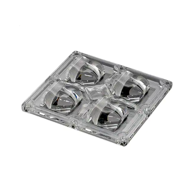
SEALING AND INGRESS PROTECTION OF LEDiL OPTICS
Many LEDiL modules are designed to be sealed against
environmental hazards with commonly available potting
compounds. Sealant can be applied with a dispenser either
manually or with an automated XY-table.
Silicone seal of IP-2X6 module
Before adding any sealing compounds, ensure the installation
surface, and the optic with its accessories are even.
Modules that have an integrated silicone gasket do not need to
be potted. To ensure intended level of ingress protection, please
make sure that the silicone gasket is correctly in place before
installation.
Only apply potting compound outside the
optical areas. STRADA lenses for example
are designed with barrier walls to keep
the compound out of the lenses.
Note! In order to maintain the desired level of ingress protection, screws with thread-locking fluids
should be thoroughly tested in advance for VOC (volatile organic compounds) or stress cracking,
and any remaining cutting fluids used in heat sink machining must be carefully removed. Solid
thread-locking screws should be used. The temperature and pressure differentials inside and outside
the lens can cause seal performance to degrade over time. If more ventilation is needed inside the
lens this must be done in such a way as to not compromise the ingress protection. E.g. by using
ventilation solutions from 3rd party manufacturers.
IP ratings indicated in LEDiL product specifications are based on IEC 60598-1:2014 ed. 8.0 and are
conducted internally. The final IP rating is subject to design and surface finish of luminaire parts and
must be individually tested.
The information contained herein is the property of LEDiL Oy, Joensuunkatu 13, FI-24100 SALO, Finland and is subject to change without notice. Please visit
www.ledil.com for additional information, such as the latest photometric files, 3D mechanical models, and application notes relating to handling, gluing and taping.
29
�LEDiL Installation Guide
THERMAL MANAGEMENT
When working with LED lighting one important issue to take into consideration is heat.
Good thermal design plays a key role in the performance and lifetime of the application.
There are three different ways for heat to transfer: conduction, convection and radiation.
Always make sure that the thermal management is sufficient enough for the application.
Conduction is the transfer of heat through solid
materials with direct contact. For example the
heat from an LED junction to the heat sink is
transferred by conduction.
Convection is the transfer of heat through the
movement of gases or fluids. A typical example
in LED applications is the heat transferred from
heat sink to air.
Radiation is the transfer of thermal energy by
electromagnetic radiation. This radiation causes
thermal motion of charged particles in matter.
In LED applications transfer through radiation is
found in the light itself. This is extremely important
to remember since LEDs keep getting more and
more powerful.
The best choice of optic is not always the material
that can handle more heat, because some
materials absorb more radiant flux than others.
This basically means that an optics efficiency is
directly linked to how hot the lens will get.
LEDiL SECONDARY OPTICS ARE DESIGNED AND MANUFACTURED TO MEET
THE HIGHEST POSSIBLE EFFICIENCY RATES. THIS NOT ONLY PROVIDES GOOD
LIGHTING RESULTS, BUT GIVES THE PRODUCT A LONGER LIFETIME AS WELL.
The information contained herein is the property of LEDiL Oy, Joensuunkatu 13, FI-24100 SALO, Finland and is subject to change without notice. Please visit
www.ledil.com for additional information, such as the latest photometric files, 3D mechanical models, and application notes relating to handling, gluing and taping.
30
�LEDiL Installation Guide
HEAT SINK MACHINING
All heat sink machining needs to be done before lens assembly. Some lenses need holes for wires and
for fastening. For example LEDiL’s STRADA-IP-2X6 products need to be fastened to the heat sink with
screws. After cable holes and threaded screw holes are machined, ensure that the anodized heat sink
surface is even. Screw thread hole accuracy is ±0.1 mm. Vertical straightness tolerance for screws is
±⊥0.1 mm A. Please be sure to remove all aluminum particles from the holes and the heat sink surface.
THERMAL INTERFACE MATERIALS
For good heat transfer, a thermal interface material must be used between the heat sink and the PCB/
COB LED. This material can be thermal pad, thermal glue, thermal paste, phase change material
or double-sided thermal tape. The material choice depends on the situation and power used by the
application. The thermal resistance of the thermal interface depends on the thermal conductivity of the
material, material thickness, area and the pressure applied to the interface. We recommend using a
thin layer of thermal interface material to minimize thermal resistance.
It is always the customer’s responsibility to ensure reliable and sufficient cooling and heat transfer
between all luminaire components. If a sufficient amount of pressure on the heat sink cannot be
maintained over time we recommended using either thermal glue and/or screws for the PCB/LED
fastening.
While using thermal interface materials, remember that the material needs to be chemically compatible
with the LEDs. Bad material choice might significantly reduce the LEDs lifetime. For example Cree has
created a test method for chemical compatibility. More information about the test can be found on
Cree’s web page.
The information contained herein is the property of LEDiL Oy, Joensuunkatu 13, FI-24100 SALO, Finland and is subject to change without notice. Please visit
www.ledil.com for additional information, such as the latest photometric files, 3D mechanical models, and application notes relating to handling, gluing and taping.
31
�LEDiL Installation Guide
THERMAL MEASUREMENTS
Infrared (IR) imaging and thermocouple measurement systems can be used for monitoring temperatures
in LED applications, but the following must be acknowledged.
• IR imaging is a preferred method for lens and reflector temperature measurements
• Low emissivity surfaces are challenging to measure with an IR camera because reflected
temperatures can also be seen in thermal image (1)
• Thermocouples cannot be placed on top of a lens due to the absorption of the radiant flux (2)
• Tiny thermocouples (AWG 40 recommended) can be used to measure LED case, PCB and heat
sink temperatures where radiant flux doesn’t interfere, and target surfaces cannot be exposed to
the IR camera
(2)
(1)
(2)
LENSES
Switch on the light and let temperatures rise until they stabilize. Remove any obstacles (e.g. glass
cover) quickly to expose the target surface and take an image on the top surface of the lens. Start
to record video sequence and turn the lens over quickly to catch the maximum temperature from the
bottom side of the lens.
REFLECTORS
Attach a thermocouple on the surface of the reflector with a small aluminum tape and monitor
temperatures until they stabilize (3). Paint the target area, attach a tape with known emissivity or
remove metallization on the outer surface of the reflector and take an IR image from that area (4).
COB LEDs
LED case temperature, Tc, can be measured with a thermocouple that is firmly glued/soldered to the
Tc measurement point of the LED module (5).
(3)
(4)
(5)
The information contained herein is the property of LEDiL Oy, Joensuunkatu 13, FI-24100 SALO, Finland and is subject to change without notice. Please visit
www.ledil.com for additional information, such as the latest photometric files, 3D mechanical models, and application notes relating to handling, gluing and taping.
32
�LEDiL Installation Guide
METAL COATING
Different materials and coatings used by LEDiL have to undergo numerous tests before being accepted.
All the materials and coatings must be permanent, durable and show no signs of peeling, fingerprints,
cracks, black spots, scratches, smudging or discoloration.
We always heat test beyond our recommended limits to fully ensure our products quality. For more
extreme environments some materials have been tested with diluted NaOH liquid and in an artificially
created salt mist. These surfaces should be completely undamaged to pass.
Both the HMDS and lacquer layer increase aluminium coating durability, but the reflector must be
protected from water and other hazards. Weather exposure tests must be carried out during the design
process.
The information contained herein is the property of LEDiL Oy, Joensuunkatu 13, FI-24100 SALO, Finland and is subject to change without notice. Please visit
www.ledil.com for additional information, such as the latest photometric files, 3D mechanical models, and application notes relating to handling, gluing and taping.
33
�LEDiL Installation Guide
VACUUM EVAPORATION PVD
LEDiL uses vacuum evaporation PVD (Physical Vapor Deposition) to add a reflective aluminum coating
to PC reflectors. Before aluminum can be added, adhesion between the reflectors and the aluminum
coating must be improved. This is conventionally done by adding a layer of lacquer to the reflector
surfaces.
• High quality both functionally and decoratively
• Reflectors will not be subject to chemical of thermal stress
• Good performance in cross-cut test
1) Top lacquer (to protect surface)
2) Al coat (in vacuum)
1
2
3
3) Base lacquer (to improve adhesion)
4) Substrate (part to be coated)
4
HMDS
HMDS is a simplified name for a glow polymerization method. Plasma treatment is first used to clean
the reflector surfaces of any unfavorable materials to improve adhesion. Then the aluminum coating
is added via vacuum evaporation and finally HMDS-monomers are added and a polymerization
reaction takes place.
• Thin and protective layer
• Good optical performance
• Good durability against heat
1
2
3
1) HMDS plasmapolymerisation (to protect surface)
2) Al coat (in vacuum)
4
3) Glow discharge activation of surface (to improve adhesion)
4) Substrate (part to be coated)
The information contained herein is the property of LEDiL Oy, Joensuunkatu 13, FI-24100 SALO, Finland and is subject to change without notice. Please visit
www.ledil.com for additional information, such as the latest photometric files, 3D mechanical models, and application notes relating to handling, gluing and taping.
34
�LEDiL Installation Guide
STORAGE
To maintain long-term product quality under storage, please ensure that the environment is kept at
normal room temperature without too much humidity and that the products are kept in their original
packaging.
LINKS TO USEFUL INFORMATION:
Guides documents and certificates
www.ledil.com/support/
Application related guides and examples
www.ledil.com/application-areas/
Product catalogue
www.ledil.com/product_catalogue
New products catelogue
www.ledil.com/latest_products_catalogue
Search for products
www.ledil.com/search/
Contact Us
www.ledil.com/contacts/
And for all other information, references and to subscribe LEDiL newsletter please visit
www.ledil.com
LIGHT THAT IS RIGHT
Follow LEDiL in social media:
The information contained herein is the property of LEDiL Oy, Joensuunkatu 13, FI-24100 SALO, Finland and is subject to change without notice. Please visit
www.ledil.com for additional information, such as the latest photometric files, 3D mechanical models, and application notes relating to handling, gluing and taping.
35
�