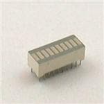
Light Bars
LTL-2000 Series
Features
Rectangular light bar.
Choices of three bright colors-green/yellow/high efficiency red.
Large, bright, uniform light emitting areas.
Low power requirement.
Excellent ON-OFF contrast.
Can be used with panel and legend mount.
Easy mounting on P.C. board.
Categorized for light output.
Yellow and green categorized for dominant wavelength.
Description
The LTL-2300/2400/2500/2600/2700/2800 series light bars are rectangular light sources designed for a variety of
applications where a large bright source of light is required. These light bars are configured in single-in-line and dualin-line packages. The green series devices utilize LED chips which are made from GaP on a transparent GaP
substrate. The yellow and high efficiency red series devices utilize LED chips which are made trom GaAsP on a
transparent GaP substrate. All devices have white bar.
Devices
Part No.
Size of Light Emitting Areas
Green
Yellow
Hi. Eff.
Red
2500G
2400Y
2300HR
8.89mm
2550G
2450Y
2350HR
19mm
2800G
2700Y
2600HR
8.89mm
3.81mm(.350 in
2855G
2755Y
2655HR
8.89mm
2820G
2720Y
2620HR
8.89mm
2885G
2785Y
2685HR
8.89mm
3.81mm(.350 in
3.76mm(.748 in
.150 in.)
.148 in.)
Package
Dimension
A
9-36
A
B
B
.150 in.)
C
C
8.89mm(.350 in
.350 in.)
D
D
3.81mm(.350 in
.150 in.)
E
E
F
F
19.05mm(.350 in
.750 in.)
Package Dimensions
A. LTL-2300/2400/2500
Internal
Circuit Diagram
B. LTL-2350/2450/2550
�D. LTL-2655/2755/2855
E. LTL-2620/2720/2820
F. LTL-2685/2785/2885
Notes : All dimensions are in millimeters (inches). Tolerance:
DISPLAYS
C. LTL-2600/2700/2800
0.25mm (0.010") unless otherwise noted.
Pin Connection
Connection
Pin
No.
A LTL-2300/2400/2500
B LTL-2350/2450/2550
C LTL-2600/2700/2800
D LTL-2655/2755/2855
1
Cathode A
Cathode A
Cathode A
Cathode A
2
Anode A
Anode A
Anode A
Anode A
3
Cathode B
Cathode B
Anode B
Anode B
4
Anode B
Anode B
Cathode B
Cathode B
5
Cathode C
Cathode C
Cathode C
6
Anode C
Anode C
Anode C
7
Cathode D
Anode D
Anode D
8
Anode D
Cathode D
Cathode D
9-37
�Connection
Pin
No.
E. LTL-2620/2720/2820
F. LTL-2685/2785/2885
1
Cathode A
Cathode A
2
Anode A
Anode A
3
Anode B
Anode B
4
Cathode B
Cathode B
5
Cathode C
Cathode C
6
Anode C
Anode C
7
Anode D
Anode D
8
Cathode D
Cathode D
9
Cathode E
Cathode E
10
Anode E
Anode E
11
Anode F
Anode F
12
Cathode F
Cathode F
13
Cathode G
Cathode G
14
Anode G
Anode G
15
Anode H
Anode H
16
Cathode H
Cathode H
Internal Circuit Diagrams
A. LTL-2300/2400/2500
B. LTL-2350/2450/2550
C. LTL-2600/2700/2800
D. LTL-2655/2755/2855
E. LTL-2620/2720/2820
F. LTL-2685/2785/2885
Absolute Maximum Ratings at Ta=25
Green
Yellow
Hi.- Eff. Red
Unit
Power Dissipation Per Chip
75
60
75
mW
Peak Forward Current Per Chip
(1/10 Duty Cycle, 0.1ms Pulse Width)
100
80
100
mA
Continuous Forward Current Per Chip
Derating Linear from 25 Per Chip
25
0.33
20
0.27
25
0.33
mA
mA/
5
5
Parameter
Reverse Voltage Per Chip
-35
to +85
Storage Temperature Range
-35
to +85
Solder Temperature 1/16 Inch Below Seating Plane for 3 Seconds at 260
9-38
5
Operating Temperature Range
V
�Electrical/Optical Characteristics at Ta=25
Parameter
Symbol
Unit
Test
Condition
mcd
IF=10mA
635
nm
IF=20mA
40
nm
IF=20mA
623
nm
IF=20mA
V
IF=20mA
Min.
Typ.
2300
1.4
4.2
2350
3.5
8
1.4
4.2
4.2
LTL-
Average Luminous
2600
IV
Intensity Per Bar
2620
1.4
2655
3.5
8
2685
7
16
P
Peak Emission Wavelength
Spectral Line Half-Width
d
Dominant Wavelength
Forward Voltage, and Bar
VF
Reverse Current, and Bar
IR
2.0
Max.
2.6
100
A
VR=5V
DISPLAYS
Hi.-Eff Red LTL-2300HR/2600HR
Yellow LTL-2400Y/2700Y
Parameter
Symbol
Unit
Test
Condition
mcd
IF=10mA
585
nm
IF=20mA
35
nm
IF=20mA
588
nm
IF=20mA
V
IF=20mA
Min.
Typ.
2400
1.4
4.2
2450
3.5
8
1.4
4.2
4.2
LTL-
Average Luminous
2700
IV
Intensity Per Bar
2720
1.4
2755
3.5
8
2785
7
16
P
Peak Emission Wavelength
Spectral Line Half-Width
d
Dominant Wavelength
Forward Voltage, and Chip
VF
Reverse Current, and Chip
IR
2.1
Max.
2.6
100
A
VR=5V
Green LTL-2500G/2800G
Parameter
LTL-
Symbol
Unit
Test
Condition
mcd
IF=10mA
565
nm
IF=20mA
30
nm
IF=20mA
569
nm
IF=20mA
V
IF=20mA
Min.
Typ.
2500
1.4
4.2
2550
3.5
8
1.4
4.2
4.2
Average Luminous
2800
Intensity Per Bar
2820
1.4
2855
3.5
8
2885
7
16
Peak Emission Wavelength
IV
P
Spectral Line Half-Width
Dominant Wavelength
d
Forward Voltage, and Chip
VF
Reverse Current, and Chip
IR
2.1
Max.
2.6
100
A
VR=5V
Notes: 1.Clean only in water, isopropanol,ethanol,freon TF (or equivalent).
2.Luminous intensity is measured with a light sensor and filter combination that approximates the CIE
(Commision Internationale De L’Eclairage)eye-response curve.
9-39
�Typical Electrical/Optical Characteristic Curves
(25 Ambient Temperature Unless Otherwise Noted)
9-40
�