DIY Pocket LED Gamer - Tiny Tetris!
Created by Jianan Li
https://learn.adafruit.com/diy-3d-printed-handheld-pocket-game-tiny-tetris-snake
Last updated on 2021-11-15 06:17:36 PM EST
©Adafruit Industries
Page 1 of 31
�Table of Contents
Overview
3
•
•
•
•
•
3
3
4
4
4
Menu
Brightness Adjust
Tetris
Snake
Paint
Parts & Tools
5
• Parts
• Tools and Misc
5
6
3D Printing
6
Circuit Diagram
8
• Bottom
• Top
8
9
HT16K33 Explained
10
Assembly
11
Top
12
Bottom
21
Interconnection
26
Source Code
28
©Adafruit Industries
Page 2 of 31
�Overview
I love Tetris! Nothing could compare with the satisfaction I get from clearing a line
after another. So in this guide, we are going to build a handheld game that plays not
only Tetris, but Snake and more!
Menu
When the Tiny Tetris is first turned on, you can use the left/right buttons to select
between Tetris, Snake, and the Paint program, then press the center button to enter
the program. Once you're inside a program, you can switch to the previous/next one
by holding down the center button and press the brightness adjustment buttons on
the left side.
Brightness Adjust
©Adafruit Industries
Page 3 of 31
�Tetris
• Up - Rotate
• Left/Right/Down - Move to left/right/down
• Center - Drop
Snake
• Left/Right/Up/Down - Change direction
• Center - N/A
Paint
• Left/Right/Up/Down - Move cursor
• Center - Draw/Clear dot
• Hold center for 3s - Clear canvas
©Adafruit Industries
Page 4 of 31
�Parts & Tools
Parts
• 1 x Adafruit Pro Trinket (http://adafru.it/2000) - this is the brains of the game
• 1 x PowerBoost 500 Charger (http://adafru.it/1944) - this is the power supply,
which manages the battery recharging and conversion
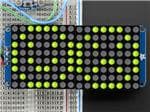
• 1 x 16x8 1.2'' LED Matrix + Backpack (http://adafru.it/2040) - pick any color and
style, I personally like the square pixels best
• 1 x Lithium Ion Polymer Battery (http://adafru.it/1578) - 500mAh is perfect
• 1 x Thru-hole 5-way Navigation Switch (http://adafru.it/504) - this little joystick
works well for gaming
• 1 x SPDT Slide Switch (http://adafru.it/805) - on off switch
©Adafruit Industries
Page 5 of 31
�• 3 x Tactile Switch Buttons (http://adafru.it/1489) (one missing from the picture
above)
• 30AWG Stranded-Core Wire (http://adafru.it/2001) (in various colors) - or any
ribbon wire you have around the workbench!
• 7 x 10kΩ Through Hole Resistors
• 5 x M2x5/6mm Flat Socket Head Cap Screw
• 8 x Neodymium Magnets 1/4 x 1/16 Inch
Tools and Misc
• Soldering Iron (http://adafru.it/1204)
• Helping Third Hand (http://adafru.it/291)
• Wire Stripper (http://adafru.it/527)
• Flush Cutter (http://adafru.it/152)
• Pliers (http://adafru.it/1368)
• Screwdriver (http://adafru.it/822)
• Super Glue
3D Printing
Download STLs on Thingiverse
https://adafru.it/dWH
The enclosure is designed in SolidWorks, and printed on a Makerbot Replicator 2 but
will fit in nearly any small 3D printer bed. Customize it with your favorite logo!
Makerbot Desktop Print Settings:
• Infill: 15%
• Shells: 2
• Layer Height: 0.10mm
• Extruder Temperature: 230°C
• Speed while Extruding: 90 mm/s
• Speed while Traveling: 150mm/s
• With raft but no support
©Adafruit Industries
Page 6 of 31
�©Adafruit Industries
Page 7 of 31
�Circuit Diagram
Bottom
©Adafruit Industries
Page 8 of 31
�This first circuit diagram contains all parts mounted on the bottom half of enclosure.
The JST connector on the PowerBoost 500 Charger goes to the LiPo battery, which is
not shown in the picture. The four wires that connect to the 16x8 LED Matrix Backpack
are the only ones that connect between the bottom and top half of the enclosure.
Top
The second circuit diagram contains everything mounted on the top half of the
enclosure. This is a view from the inside of the enclosure, which means that both the
LED Matrix Backpack and the joystick are facing away from us. If it seems confusing,
the assembly guide on the next page will definitely help you understand
better. All seven resistors shown in this circuit diagram have a value of 10kΩ.
©Adafruit Industries
Page 9 of 31
�At this point, you might be asking why we're wiring the buttons to the LED Matrix
Backpack instead of the Pro Trinket. There are a couple good reasons why we're
doing this. One is that we don't need to connect so many wires between the top and
bottom half of the enclosure, which makes the assembly much easier. But the
underlying reason has to do with the HT16K33 chip located on the LED Matrix
Backpack. Let me explain more on the next page.
HT16K33 Explained
So what is the HT16K33 (https://adafru.it/aMy)? It's the name of the chip on the LED
Matrix Backpack.
It's a wonderful chip! Not only is it capable of driving a 16x8 LED Matrix, but reading a
pushbutton matrix with a maximum size of 13x3. In fact, this is how HT16K33 is used
on the Adafruit Trellis (http://adafru.it/1616) to read the 16 pushbuttons.
©Adafruit Industries
Page 10 of 31
�The HT16K33 refreshes the LED matrix with a frequency of about 100Hz. In each of
the 10ms frame, it first refreshes the display, and then scans the button matrix for the
state of every single one of those 13x3=39 buttons. But it's gets more interesting!
The HT16K33 does not immediately tell you when any of the buttons is pressed.
Instead, it waits for one additional cycle, which is a total of 20ms, to confirm the
reading on all the buttons, and store the confirmed readings in its internal registers.
It debounces the buttons for you! How cool is that?
So instead of writing code for debouncing the buttons on the Pro Trinket, we can ask
the HT16K33 over I2C about the state of all buttons once every 20ms (50Hz). That's
exactly what we are doing in this tutorial!
Assembly
Now let's start to put these components together to build our Tiny Tetris! The entire
assembly process consists of three parts: the top half of the enclosure, the bottom
half, and the interconnection.
©Adafruit Industries
Page 11 of 31
�Top
Let's start with the soldering the LED matrices to the Backpack. After all 32 pins have
been soldered, carefully trim the pins with a flush cutter.
©Adafruit Industries
Page 12 of 31
�Use a pair of pliers to straighten the legs of the two pushbuttons and then insert them
into the cavities on the left side of the enclosure.
©Adafruit Industries
Page 13 of 31
�Be careful when soldering inside the enclosure. Your soldering iron will deform
the PLA plastic if they come in contact with each other (see the burn mark in the
picture below.)
On the inside, you should be able to see all four pins of the pushbuttons. Bend the
inner two and join them together with some solder.
Now prepare two resistors and two short piece of wires - approximately 4cm and 5cm
respectively - and solder each wire to a resistor.
©Adafruit Industries
Page 14 of 31
�Then solder each of them to the outer two pins of the pushbuttons. The 4cm wire on
the left, 5cm on the right.
©Adafruit Industries
Page 15 of 31
�To prepare the joystick for soldering/mounting, straighten its legs, bend them 90
degrees outward, and then cut them to about half the length.
Put a little bit of solder on all six pins.
Make sure the joystick is in the correct orientation. The distance between the top
and middle pins should be smaller than the distance between the middle and
bottom pins.
©Adafruit Industries
Page 16 of 31
�Prepare 5 pairs of resistors and short wires (about 8cm each). We'll cut them to the
exact lengths needed later.
Solder the five resistors to the five pins on the joystick. Make sure the solder makes
firm connections between the resistors and the joystick.
©Adafruit Industries
Page 17 of 31
�Push the joystick into the square opening. It should be a tight fit. If not, put a little bit
of super glue along the seam to fix the joytick in place.
Now push the LED matrix backpack into the largest opening, and use four M2 screws
to secure it in place. Make sure that the I2C pins (VCC, GND, SCL, SDA) are near the
top of the device.
©Adafruit Industries
Page 18 of 31
�Solder the two white wires from the pushbutton resistors to the 1st and 2nd pins on
the left side of the top LED matrix.
Then use a yellow wire to connect the joystick to the solder joint between the two
pushbuttons, and another to connect the solder joint to the 3rd pin on the left side of
the top LED matrix.
Solder a white wire to each of the resistors on the left side of the joystick, and make
the connections shown in the picture above. If the picture looks confusing, please
refer to the circuit diagram on the previous page.
©Adafruit Industries
Page 19 of 31
�Then we can solder the last set of wires to connect the two resistors on the right side
of the joystick to the backpack. Again, please refer to the circuit diagram on the
previous page if the picture looks confusing.
Now we have the top half of the Tiny Tetris with all components assembled and wires
soldered.
©Adafruit Industries
Page 20 of 31
�Bottom
Start by putting the Pro Trinket and the PowerBoost 500 Charger into the enclosure.
Use a M2 screw to secure the Pro Trinket. Gently push the PowerBoost into the cavity
to fix it in place. It should be more or less a friction fit.
©Adafruit Industries
Page 21 of 31
�Push the SPDT switch into the cavity at the top of the enclosure, and the pushbutton
on the right side of the enclosure. You should be able to see the pins of the switch
and pushbutton on the inside of the enclosure.
©Adafruit Industries
Page 22 of 31
�Use three short wires to connect the power lines between the PowerBoost and the
Pro Trinket.
Pro Trinket --- Powerboost
• BAT --- +
• G --- GND
• BUS --- USB
These connections allow us to recharge the battery through the micro USB port on
the Pro Trinket in addition to the one on the PowerBoost 500 Charger, and have the
Pro Trinket powered by the boosted 5V source from the PowerBoost.
©Adafruit Industries
Page 23 of 31
�Then use two more short wires to connect the reset button to the Pro Trinket.
Connect the RST pin to the left side of the pushbutton, and one of the GND pins to
the right side of the pushbutton.
Now connect the EN and GND pins on the PowerBoost to the left and middle pins on
the SPDT switch. Be sure to run the wires on the side instead of going straight to the
switch. We want to leave some space for the LiPo battery.
©Adafruit Industries
Page 24 of 31
�Finally we can connect the battery to the JST connector on the PowerBoost to test
the circuit. If you slide the SPDT switch to the right, the boost converter will be
enabled, and the system will power on. Make sure that you see both the blue LED on
the PowerBoost and the green LED on the Pro Trinket light up.
Also, you can test the reset button as well by pressing the pushbutton and see if the
Pro Trinket reset itself.
If everything is working as expected, we can move on to make the connections
between the top and bottom half of the Tiny Tetris.
©Adafruit Industries
Page 25 of 31
�Interconnection
Solder four wires to the I2C pins on the Backpack. The colors I used in the picture
above are the same as the ones in the circuit diagram on the previous page.
• Red: VCC
• Black: GND
• Blue: SDA
• Yellow: SCL
©Adafruit Industries
Page 26 of 31
�Connect the four wires to the Pro Trinket and PowerBoost as listed below:
• Red: 5V on the PowerBoost
• Black: GND on the Pro Trinket
• Blue: A4 on the Pro Trinket
• Yellow: A5 on the Pro Trinket
Finally use some super glue to secure the eight magnets to the cavities on the
enclosure. Wait for a little bit to allow the glue to dry completely.
©Adafruit Industries
Page 27 of 31
�The two pieces snap together easily, and we've finally finished the entire assembly
process!
Source Code
You can browse the source code on the GitHub repository here (https://adafru.it/EMK)
Click the Download: Project Zip below to just download the whole thing in a zip file.
Uncompress and be sure to change the name of the folder to Mini_LED_Gamer after
download.
Download Source Code
https://adafru.it/EMK
The code for this project doesn't use any external libraries. Instead of using Wire.h to
talk to the HT16K33 chip on the LED Matrix Backpack, it uses the i2c.h for the I2C
interface.
The reason is that a timer interrupt is used to both refresh the LED matrix and read
the state of all the buttons at approximately 50Hz. However, Wire.h uses the timer
interrupt for the I2C interface, and you can't have two timer interrupts running inside
of each other. The i2c.h does not use any timer interrupt, thus avoiding the conflict.
It's a little more advanced but works well!
HT16K33.cpp is similar to the Adafruit_LEDBackpack library, but it works with i2c.h
instead of Wire.h, and it not only drives the LED matrix but also checks the state of
the pushbuttons.
Tetris.cpp, Snake.cpp, and Paint.cpp are each responsible for an individual program
that runs on the Tiny Tetris.
#include
#include
#include
#include
"HT16K33.h"
"Tetris.h"
"Snake.h"
"Paint.h"
// ADC clock configurations
#define ADPS_16 _BV(ADPS2)
#define ADPS_32 _BV(ADPS2)|_BV(ADPS0)
#define ADPS_128 _BV(ADPS2)|_BV(ADPS1)|_BV(ADPS0)
// Buttons: bits 0-6 in the first byte of the key-scan matrix
#define LEFT 6
#define SELECT 1
#define DOWN 2
©Adafruit Industries
Page 28 of 31
�#define
#define
#define
#define
UP 5
RIGHT 0
BRIGHTNESS_UP 4
BRIGHTNESS_DOWN 3
// Objects
HT16K33 ht(0x70);
Tetris tetris;
Snake snake;
Paint paint(3,3);
// I2C address of the HT16K33 IC
// initilize cursor position to (3,3)
uint8_t* getMenu();
void changeOption(int8_t i);
void changeMode();
// Mode: 0-Undecided; 1-Tetris; 2-Snake; 3-Paint
uint8_t mode=0;
// Interrupt Variables
uint8_t interruptCounter2Hz = 0;
ISR(TIMER1_OVF_vect){
// things that need to be done at 50Hz
ht.readButtons();
processButtons();
switch(mode) {
case 0:
ht.storeToBuffer(getMenu());
break;
case 1:
ht.storeToBuffer(tetris.getActiveBoard());
break;
case 2:
ht.storeToBuffer(snake.getActiveBoard());
break;
case 3:
ht.storeToBuffer(paint.getActiveCanvas());
}
ht.refreshDisplay();
// things that happen less frequently
interruptCounter2Hz++;
if (interruptCounter2Hz==25) {
interruptCounter2Hz=0;
paint.flashCursor();
}
}
void processButtons() {
// These two buttons are fixed
if (ht.allowToMove(BRIGHTNESS_DOWN,25,6) && ht.getButtonHoldTime(SELECT)==0)
ht.decreaseBrightness();
if (ht.allowToMove(BRIGHTNESS_UP,25,6) && ht.getButtonHoldTime(SELECT)==0)
ht.increaseBrightness();
// change to the previous/next program by pressing holding select and press the
brightness control buttons
if (mode!=0 && ht.getButtonHoldTime(SELECT)>10) {
if (ht.getButtonFirstPress(BRIGHTNESS_UP)) {
changeOption(-1);
changeMode();
}
else if (ht.getButtonFirstPress(BRIGHTNESS_DOWN)){
changeOption(1);
changeMode();
}
}
// control for different programs
©Adafruit Industries
Page 29 of 31
�switch(mode) {
case 0:
if (ht.getButtonFirstPress(LEFT)) changeOption(-1);
if (ht.getButtonFirstPress(RIGHT)) changeOption(1);
if (ht.getButtonFirstPress(SELECT)) changeMode();
break;
case 1:
if (tetris.gameRunning) {
if (ht.allowToMove(UP,100,4)) tetris.rotatePiece();
if (ht.allowToMove(DOWN,15,2)) tetris.movePiece(0,1);
if (ht.allowToMove(LEFT,15,2)) tetris.movePiece(-1,0);
if (ht.allowToMove(RIGHT,15,2)) tetris.movePiece(1,0);
if (ht.getButtonFirstPress(SELECT)) tetris.dropPiece();
}
else {
if (ht.getButtonFirstPress(SELECT)) tetris.init();
}
break;
case 2:
if (snake.gameRunning) {
if (ht.getButtonFirstPress(UP)) snake.changeDirection(0,-1);
if (ht.getButtonFirstPress(DOWN)) snake.changeDirection(0,1);
if (ht.getButtonFirstPress(LEFT)) snake.changeDirection(-1,0);
if (ht.getButtonFirstPress(RIGHT)) snake.changeDirection(1,0);
}
else {
if (ht.getButtonFirstPress(SELECT)) snake.init();
}
break;
case 3:
if (ht.allowToMove(UP,25,2)) paint.moveCursor(0,-1);
if (ht.allowToMove(DOWN,25,2)) paint.moveCursor(0,1);
if (ht.allowToMove(LEFT,25,2)) paint.moveCursor(-1,0);
if (ht.allowToMove(RIGHT,25,2)) paint.moveCursor(1,0);
if (ht.getButtonFirstPress(SELECT)) paint.draw();
if (ht.getButtonHoldTime(SELECT)==150) paint.clearCanvas();
}
}
void setup(){
// Set randomSeed; the first few random() are not used because they never change
randomSeed(analogRead(A0));
for (uint8_t i=0;i 1/20000us = 50Hz
TCCR1A = 0;
// clear TCCR1A (not used)
TCCR1B = _BV(WGM13) | _BV(CS11); // mode 8(PWM), set prescalar=8;
TIMSK1 = _BV(TOIE1);
// Enable Overflow Interrupt
}
void loop(){
// For both the tetris and snake, they have a function called "run" as the main
game loop.
// For the paint program, all the actions are handled in the timer interrupt, so
there is nothing to do in the main loop
switch(mode) {
©Adafruit Industries
Page 30 of 31
�case 0:
break;
case 1:
tetris.run(); break;
case 2:
snake.run(); break;
case 3:
;
}
}
©Adafruit Industries
Page 31 of 31
�