LK162A-4T
Including the LK162A-4T-USB varia nt
Technical Manual
Revision 1.3
PCB Revision: 1.0 or Higher
Firmware Revision: 7.3 or Higher
�Revision History
Revision
1.3
1.2
1.1
1.0
Date
January 4, 2018
March 31, 2016
March 12, 2014
February 20, 2014
Description
Correction to Set Non-Standard Baud Rate command
Revision to Commands for Firmware Revision 7.3
Revision and correction to Colour in Ordering Options
Initial Release
Author
Divino
Divino
Martino
Clark
�Contents
1 Introduction ............................................................................................................................................... 1
2 Quick Connect Guide.................................................................................................................................. 2
2.1 Available Headers ............................................................................................................................... 2
2.2 Standard Module ................................................................................................................................ 3
Recommended Parts ............................................................................................................................. 3
Serial Connections................................................................................................................................. 3
I2C Connections ..................................................................................................................................... 4
2.3 USB Module ........................................................................................................................................ 5
Recommended Parts ............................................................................................................................. 5
USB Connections ................................................................................................................................... 5
3 Software ..................................................................................................................................................... 6
3.1 uProject ............................................................................................................................................... 6
3.2 Application Notes................................................................................................................................ 7
4 Hardware.................................................................................................................................................... 8
4.1 Standard Model .................................................................................................................................. 8
Communication/Power Header ............................................................................................................ 8
Protocol Select Jumpers ........................................................................................................................ 8
4.2 USB Model........................................................................................................................................... 9
Four Pin USB Header ............................................................................................................................. 9
4.3 Common Features ............................................................................................................................... 9
General Purpose Outputs ..................................................................................................................... 9
5 Troubleshooting ....................................................................................................................................... 10
5.1 Power ................................................................................................................................................ 10
5.2 Display ............................................................................................................................................... 10
5.3 Communication ................................................................................................................................. 11
5.4 Manual Override ............................................................................................................................... 11
6 Commands ............................................................................................................................................... 12
6.1 Communication ................................................................................................................................. 12
6.2 Text.................................................................................................................................................... 13
6.3 Special Characters ............................................................................................................................. 15
�6.4 General Purpose Output ................................................................................................................... 17
6.5 Keypad............................................................................................................................................... 18
6.6 Display Functions .............................................................................................................................. 21
6.7 Data Security ..................................................................................................................................... 22
6.8 Miscellaneous ................................................................................................................................... 23
7 Appendix .................................................................................................................................................. 25
7.1 Command Summary ......................................................................................................................... 25
7.2 Character Sets ................................................................................................................................... 28
7.3 Block Diagram ................................................................................................................................... 29
7.4 Environmental Specifications............................................................................................................ 29
7.5 Electrical Tolerances ......................................................................................................................... 29
7.6 Dimensional Drawings ...................................................................................................................... 30
7.7 Optical Characteristics ...................................................................................................................... 31
8 Ordering ................................................................................................................................................... 31
8.1 Part Numbering Scheme ................................................................................................................... 31
8.2 Options .............................................................................................................................................. 31
8.3 Accessories ........................................................................................................................................ 32
9 Definitions ................................................................................................................................................ 33
10 Contact ................................................................................................................................................... 33
�1 Introduction
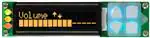
Figure 1: LK162A-4T Display
The LK162A-4T is an intelligent alphanumeric liquid crystal display designed to decrease development
time by providing an instant solution to any project. In addition to the RS232, TTL and I2C protocols
available in the standard model, the USB communication model allows the LK162A-4T to be connected
to a wide variety of host controllers. Communication speeds of up to 115.2kbps for serial protocols and
100kbps for I2C ensure lightning fast display updates.
The simple command structure permits easy software control of many settings including backlight
brightness, screen contrast, and baud rate. On board memory provides up to forty custom characters
which can be saved within the unit and recalled for start screens, bar graphs or larger numbers.
User input on the LK162A-4T is available through a four key, integrated tactile keypad and three bicolour LEDs provide visual output. An additional two general purpose outputs on the back of the unit
provide simple, switchable five volt sources.
The versatile LK162A-4T, with all the features mentioned above, is available in a variety of colour,
voltage, and temperature options to suit almost any application.
1
Command Summary
�2 Quick Connect Guide
2.1 Available Headers
Figure 2: LK162A-4T Standard and USB Module Header Locations
Table 1: List of Available Headers
#
1
2
3
Header
Mini USB Connector
GPO Header
Communication/Power Connector
Mate
EXTMUSB3FT/INTMUSB3FT
None Offered
SCCPC5V/BBC
Command Summary
Population
USB Model Only
All Models
Standard Model Only
2
�2.2 Standard Module
The standard version of the LK162A-4T allows for user configuration of three common communication
protocols. First, the unit can communicate using serial protocol at either RS323 or TTL voltage levels.
Second, it can communicate using the Inter-Integrated Circuit connect, or I2C protocol. Connections for
each protocol can be accessed through the four pin Communication/Power Header as outlined in the
Serial Connections and I2C Connections sections below.
Recommended Parts
The most common cable choice for any alphanumeric Matrix Orbital
Display, the Communication/ Power Cable offers a simple connection
to the unit with familiar interfaces. DB9 and floppy power headers
provide all necessary input to drive your display.
Figure 3: Communication/Power Cable
(SCCPC5V)
For a more flexible interface to the LK162A-4T a Breadboard Cable
may be used. This provides a simple four wire connection that is
popular among developers for its ease of use in a breadboard
environment.
Figure 4: Breadboard Cable (BBC)
Serial Connections
A serial interface provides a classic connection to the LK162A-4T. The Communication/Power Cable is
most commonly used for this set up as it provides connections for DB9 serial and floppy power cables.
To place your board in Serial mode, adhere to the steps laid out below.
1. Set the Protocol Select jumpers.
RS232: Connect the three jumpers* in the 232 protocol box with the zero ohm jumper resistors
provided or an alternate wire or solder solution.
TTL: Connect the two jumpers* in the TTL protocol box.
*Note: Jumpers must be removed from all protocol boxes save for the one in use.
3
Command Summary
�2. Make the connections.
a. Connect the four pin female header of the Communication/Power Cable to the
Communication/Power Header of your LK162A-4T.
b. Insert the male end of your serial cable to the corresponding DB9 header of the
Communication/Power Cable and the mate the female connector with the desired
communication port of your computer.
c. Select an unmodified floppy cable from a PC power supply and connect it to the power header
of the Communication/Power Cable.
3. Create.
Use uProject or a terminal program to get started, and then move on with your own
development. A number of application notes are available at www.matrixorbital.ca/appnotes.
I2C Connections
A more advanced connection to the LK162A-4T is provided by the I2C protocol setting. This is best
accomplished using a breadboard and the Breadboard Cable. Power must be supplied from your
breadboard or another external source. To dive right into your application and use the LK162A-4T in I2C
mode, get started with the guidelines below.
1. Set the Protocol Select switches.
I2C: Ensure that the two I2C jumpers in the corresponding protocol box are connected while all
others are open.
2. Make the connections.
a. Connect the Breadboard Cable to the Communication/Power Header on your LK162A-4T and
plug the four leads into your breadboard. The red lead will require power, while the black
should be connected to ground, and the green and yellow should be connected to your
controller clock and data lines respectively.
b. Pull up the clock and data lines to five volts using a resistance between one and ten kilohms on
your breadboard.
3. Create.
This time you're on your own. While there are many examples within the Matrix Orbital
AppNote section, www.matrixorbital.ca/appnotes, too many controllers and languages exist to
cover them all. If you get stuck in development, it is possible to switch over to another protocol
on the standard board, and fellow developers are always on our forums for additional support.
Command Summary
4
�2.3 USB Module
The LK162A-4T-USB offers a single USB protocol for an easy connection to a host computer. This simple
and widely available protocol can be accessed using the on-board keyed, friction lock style USB
connector as outlined in the USB Connections section.
Recommended Parts
The External 4pin USB cable is recommended for the LK162A-4T-USB
display. It will connect to the keyed, friction lock style header on the unit
and provide a connection to a regular A style USB connector, commonly
found on a PC.
Figure 5: Four Pin USB Cable
(EXT4PUSB3FT)
USB Connections
The USB connection is the quickest, easiest solution for PC development. After driver installation, the
LK162A-4T-USB will be accessible through a virtual serial port, providing the same result as a serial setup
without the cable hassle. To connect to your LK162A-4T-USB please follow the steps below.
1. Set the Protocol Select jumpers.
USB: The LK162A-4T-USB offers USB protocol only. Model specific hardware prevents this unit
from operating in any other protocol, and does not allow other models to operate in USB.
Protocol Select jumpers on the USB model cannot be moved.
2. Make the connections.
Plug the mini-B header of your External Mini USB cable into your LK162A-4T-USB and the
regular USB header into your computer USB jack.
3. Install the drivers.
a. Download the latest drivers at www.matrixorbital.ca/drivers, and save them to a known
location.
b. When prompted, install the USB bus controller driver automatically
c. If asked, continue anyway, even though the driver is not signed
d. When the driver install is complete, your display will turn on, but communication will not yet be
possible.
e. At the second driver prompt, install the serial port driver automatically
f. Again, if asked, continue anyway
4. Create.
Use uProject or a terminal program to get started, and then move on with your own
development. A number of application notes are available at www.matrixorbital.ca/appnotes.
5
Command Summary
�3 Software
The multiple communication protocols available and simple command structure of the LK162A-4T
means that a variety of applications can be used to communicate with the display. Text is sent to the
display as a character string, for example, sending the decimal value 41 will result in an 'A' appearing on
the screen. A number of control characters are also activated. Commands are merely values prefixed
with a special command byte, 254 in decimal.
Table 2: Reserved Control Characters
8
Backspace
10
Control Characters
Line feed / New line 12 Clear screen / New page
13
Carriage return
Once the correct communication port is identified, the following communication settings can be applied
to communicate correctly with the LK162A-4T.
Table 3: Communication Settings
BPS
19200
Data Bits
8
Parity
None
Stop Bits
1
Flow Control
None
Finally, with a communication port identified and correctly setup simple text strings or even command
bytes can easily be transmitted to control your display.
3.1 uProject
The Matrix Orbital alphanumeric display tuner, or uProject, is offered as a free download from the
www.matrixorbital.ca support site. It allows the basic functionality of *any display to be tested using a
simple graphical user interface system.
While basic functionality can be tested using the GUI portion of the program, more advanced users will
enjoy the scripting capability found in the uploader tab. Here commands can be stacked, run, and saved
for later use. Although many commands are available to be dragged into the script dialog, perhaps the
most powerful is the raw data command found in the other branch.
*Note: The uProject AutoDetect function will not perform correctly when a USB display is connected. Please
manually configure any USB display.
Command Summary
6
�This command allows raw bytes to be sent to the display, permitting many different formats for entry
and displaying in decimal notation. Any command from this manual may be entered in decimal notation
separated by slashes.
/254/ /88/
Figure 6: uProject Command
Again, the clear screen command is sent to a connected display, this time using uProject raw data
command style. Scripts can be run as a whole using the execute command from the script menu, or as
single commands by selecting execute once. Before issuing commands, it is a good idea to ensure
communication with a display is successful using some of the more basic GUI functions in the main
window.
This program provides scratch pad upon which a tome of display projects and ideas can be assembled.
3.2 Application Notes
Full demonstration programs and code are available for Matrix Orbital Displays in the C# language from
Simple C# AppNote Pack in the Application Note section at www.matrixorbital.ca/appnotes. Difficulty
increases from beginner, with the Hello World program, to advanced with the Dallas One-Wire
temperature reading application.
Many additional applications are available in a number of different programming languages. These
programs are meant to showcase the capability of the display and are not intended to be integrated into
a final design. For additional information regarding code, please read the On Code document also found
on the support site.
7
Command Summary
�4 Hardware
4.1 Standard Model
Communication/Power Header
Table 4: Communication/Power Pinout
Figure 7: Communication/Power Header
Pin
1
2
3
4
Function
Vcc
Rx (SCL)
Tx (SDA)
Gnd
The Communication/Power Header provides a standard connector for interfacing to the LK162A-4T.
Voltage is applied through pins one and four of the four pin Communication/Power Header. Please
ensure the correct voltage input for your display by referencing Voltage Specifications before connecting
power. Pins two and three are reserved for serial transmission, using either the RS-232/TTL or clocking
data through the I²C protocol, depending on what has been selected by the Protocol Select Jumpers.
The versatile Tyco 640456-4-LF style header used can be mated to a number of connectors, the Molex
22-01-3047 for example.
Protocol Select Jumpers
The Protocol Select Jumpers provide the means necessary to toggle the LK162A-4T between RS-232, TTL
and I²C protocols. As a default, the jumpers are set to RS-232 mode with solder jumps on the RS232
jumpers. In order to place the display module in I²C mode you must first remove the solder jumps from
the RS232 jumpers and then place them on the I2C jumpers. The display will now be in I²C mode and
have a default slave address of 80, unless changed with the appropriate command. Similarly, in order to
change the display to TTL mode, simply remove the zero ohm resistors from the RS232 or I²C jumpers
and solder them to the TTL jumpers.
Command Summary
8
�4.2 USB Model
Four Pin USB Header
Table 5: USB Pinout
Pin
1
2
3
4
Figure 8: Four Pin USB Header
Function
GND
D+
DVcc
The LK162A-4T-USB comes with a keyed, friction lock style USB connector to fulfill both communication
and power needs. Most commonly used with a PC, this connection creates a virtual com port that offers
a simple power solution with a familiar communication scheme. The Molex 22-04-1061 style header
used can be mated to a number of connectors, a 22-01-1062 for example.
4.3 Common Features
General Purpose Outputs
Table 6: GPO Pinout
Pin
1
2
3
4
Figure 9: GPO Header
Function
GPO 1
GND
GPO 2
GND
A unique feature of the LK162A-4T is the ability to control relays* and other external devices using
either one of two General Purpose Outputs. Each can source up to 10mA of current at five volts when
on or sink 20mA at zero volts when off. The single row, four pin header can be interfaced to a number
of female connectors to provide control to any peripheral devices required.
*Note: If connecting a relay, be sure that it is fully clamped using a diode and capacitor in order to absorb any
electro-motive force (EMF) which will be generated.
9
Command Summary
�5 Troubleshooting
5.1 Power
In order for your LK162A-4T to function correctly, it must be supplied with the appropriate power. If the
power LED near the top right corner of the board is not illuminated, power is not applied correctly. Try
following the tips below.
First, make sure that you are using the correct power connector. Standard floppy drive power
cables from your PC power supply may fit on the Communication/Power Header; however they
do not have the correct pin out to provide power. Matrix Orbital supplies power cable adapters
for connecting to a PC, which can be found in the accessories section.
Next, check the power cable which you are using for continuity. If you don't have an ohm
meter, try using a different power cable, if this does not help try using a different power supply.
If changes have been made to the protocol select block, ensure all the appropriate protocol
select jumpers are connected and all unused protocol jumpers are disconnected.
The last step will be to check the interface connector in use on your display. If the power
connections have become loose, or you are unable to resolve the issue, please Contact Matrix
Orbital for more information.
5.2 Display
If your display is powered successfully, the Matrix Orbital logo, or user created screen should display on
start up. If this is not the case, check out these tips.
•
•
Ensure the contrast is not too high or too low. This can result in a darkened or blank screen
respectively. See the Manual Override section to reset to default.
Make sure that the start screen is not blank. It is possible to overwrite the Matrix Orbital logo
start screen, if this happens the screen may be blank. Try writing to the display to ensure it is
functional, after checking the contrast above.
Command Summary
10
�5.3 Communication
When communication of either text or commands is interrupted, try the steps below.
•
•
•
•
•
•
•
•
First, check the communication cable for continuity. If you don't have an ohm meter, try using a
different communication cable. If you are using a PC try using a different Com/USB Port.
Next, please ensure that the display module is set to communicate on the protocol that you are
using, by checking the Protocol Select Jumpers.
In serial and USB protocols, ensure that the host system and display module are both
communicating on the same baud rate. The default rate for the display module is 19200 bps.
Match Rx from your display to the transmitting pin from your host and the Tx pin to the
receiving pin.
If you are communicating to the display via I²C* please ensure that the data is being sent to the
correct address. The default slave address for the display module is 80.
In I2C mode, connect Rx to the clock line of your controller and Tx to the data output.
Unlock the display. See the Set and Save Data Lock command for more info.
Finally, you may reset the display to its default settings using the Manual Override procedure
outlined below.
*Note: I²C communication will always require pull up resistors on SCL and SDA of one to ten kilohms.
5.4 Manual Override
Should the settings of your display become altered in a way that dramatically impacts usability, the
default settings can be temporarily restored. To override the display, please follow the steps below.
1.
2.
3.
4.
Disconnect power from your display.
Hold down the bottom arrow key.
Reconnect power to your unit, and wait for the start screen before releasing the key.
Settings will be temporarily* overridden to the defaults listed in the Manual Override Settings table.
At this point any important settings, such as contrast, backlight, or baud rate, should not only be set
but saved so they remain when the override is removed.
Parameter
Backlight
Contrast
Baud Rate
2
I C Address
Value
255
128
19200
80
Table 7: Manual Override Settings
*Note: The display module will revert back to the old settings once turned off, unless desired settings are saved.
11
Command Summary
�6 Commands
6.1 Communication
1.1 Change
Baud Rate
Dec
254 57 Speed
Hex
FE 39 Speed
ASCII
■ 9 Speed
Immediately changes the baud rate. Not available in I2C. Baud rate can be temporarily forced to 19200 by a
manual override.
Speed Byte Valid settings shown below.
v7.2
Table 8: Accepted Baud Rate Values
Rate
Speed
1200
83
2400
41
4800
207
9600
103
19200
51
28800
34
38400
25
57600
16
76800
12
115200
8
2
1.2 Change I C
Slave Address
Dec
254 51 Address
v7.2
Hex
FE 33 Address
ASCII
■ 3 Address
2
Immediately changes the I C write address. Only even values are permitted as the next odd address will become
the read address. Default is 80.
Address Byte Even value.
1.3 Transmission
Protocol Select
Dec
254 160 Protocol
v7.2
Hex
FE A0 Protocol
ASCII
■ á Protocol
Selects the protocol used for data transmission from the display. Data transmission to the display is not affected.
Must be set to the protocol in use to receive data correctly.
2
Protocol Byte
1 for Serial (RS232/RS422/TTL/USB) or 0 for I C.
1.4 Set a Non-Standard
Baud Rate
Dec
254 164 Speed
v5.0
Hex
FE A4 Speed
ASCII
■ ñ Speed
Immediately changes the baud rate to a non-standard value. Baud must be a whole number between 977 and
153800. Due to rounding, error increases with baud rate, actual baud must be within 3% of desired baud to ensure
accurate communication. Not available in I2C. Can be temporarily forced to 19200 by a manual override.
Speed Short Calculations shown below, standard crystal speed is 16MHz.
𝑆𝑝𝑒𝑒𝑑 =
𝐶𝑟𝑦𝑠𝑡𝑎𝑙𝑆𝑝𝑒𝑒𝑑
−1
(8 × 𝐷𝑒𝑠𝑖𝑟𝑒𝑑𝐵𝑎𝑢𝑑)
Equation 1: Speed Byte Calculation
𝐴𝑐𝑡𝑢𝑎𝑙𝐵𝑎𝑢𝑑 =
𝐶𝑟𝑦𝑠𝑡𝑎𝑙𝑆𝑝𝑒𝑒𝑑
(8 × (𝑆𝑝𝑒𝑒𝑑 + 1))
Equation 2: Actual Baud Rate Calculation
|𝐷𝑒𝑠𝑖𝑟𝑒𝑑𝐵𝑎𝑢𝑑 − 𝐴𝑐𝑡𝑢𝑎𝑙𝐵𝑎𝑢𝑑|
< 0.03
𝐷𝑒𝑠𝑖𝑟𝑒𝑑𝐵𝑎𝑢𝑑
Equation 3: Baud Rate Error Calculation
Command Summary
12
�1.5 Software
Reset
Dec
254 253 77 79 117 110
V7.3
Hex
FE FD 4D 4F 75 6E
ASCII
■²MOun
Reset the display as if power had been cycled via a software command. No commands should be sent while the
unit is in the process of resetting; a response will be returned to indicate the unit has successfully been reset.
Response
Short Successful reset response, 254 212.
6.2 Text
2.1 Clear
Screen
Dec
254 88
Hex
FE 58
ASCII
■X
Clears the contents of the screen.
v7.2
2.2 Change the
Start Up Screen
Dec
254 64 Characters
v7.2
Hex
FE 40 Characters
ASCII
■ @ Characters
Changes the message displayed on start up. Custom characters can be included by adding their decimal value (07). Characters will automatically wrap on the display.
Characters
32 bytes, space characters can be added as needed
2.3 Auto
Scroll On
Dec
254 81
v7.2
Hex
FE 51
ASCII
■Q
The entire contents of screen are shifted up one line when the end of the screen is reached. Display default is on.
2.4 Auto
Scroll Off
Dec
254 82
v7.2
Hex
FE 52
ASCII
■R
New text is written over the top line when the end of the screen is reached. Display default is Auto Scroll on.
2.5 Set Auto
Line Wrap On
Dec
254 67
Hex
FE 43
ASCII
■C
Text will wrap to the next consecutive line once a row becomes full. Default is Auto Line Wrap on.
2.6 Set Auto
Line Wrap Off
v7.2
Dec
254 68
v7.2
Hex
FE 44
ASCII
■D
Text will skip one line when wrapping once a row becomes full. Writing order will be rows 1, 3, 2, and then 4.
Default is Auto Line Wrap on.
13
Command Summary
�2.7 Set Cursor
Position
Dec
254 71 Column Row
Hex
FE 47 Column Row
ASCII
■ G Column Row
Sets the cursor to a specific cursor position where the next transmitted character is printed.
Column Byte Value between 1 and number of character columns.
Row
Byte Value between 1 and number of character rows.
v7.2
2.8 Go
Home
Dec
254 72
Hex
FE 48
ASCII
■H
Returns the cursor to the top left of the screen.
v7.2
2.9 Move
Cursor Back
Dec
254 76
Hex
FE 4C
ASCII
■L
Moves cursor one position to the left. Cursor will obey wrap settings.
v7.2
2.10 Move
Cursor Forward
Dec
254 77
Hex
FE 4D
ASCII
■M
Moves cursor one position to the right. Cursor will obey wrap settings.
v7.2
2.11 Underline
Cursor On
Dec
254 74
Hex
FE 4A
ASCII
■J
Displays a line under the current cursor position. Can be used with block cursor.
v7.2
2.12 Underline
Cursor Off
Dec
254 75
Hex
FE 4B
ASCII
■K
Removes line under current cursor position.
v7.2
2.13 Blinking
Block Cursor On
Dec
254 83
Hex
FE 53
ASCII
■S
Displays a blinking block over the current cursor position. Can be used with underline.
v7.2
2.14 Blinking
Block Cursor Off
v7.2
Dec
254 84
Hex
FE 54
ASCII
■T
Removes blinking block over current cursor position.
Command Summary
14
�6.3 Special Characters
3.1 Create a Custom
Character
Dec
254 78 ID Data
v7.2
Hex
FE 4E ID Data
ASCII
■ N ID Data
Creates a custom character. Each character is divided into 8 rows of 5 pixels; each data byte represents one row.
Each byte is padded by three zero bits followed by five bits representing each pixel state. A one represents an on
condition while a zero is off. Characters are lost when a new memory bank is loaded, unless they are saved.
ID
Byte
Character ID, value between 0 and 7.
Data Byte[8] Character pixel data as shown below.
Table 9: Custom Degree Character
Data[1] 000 p1 p2 p3 p4 p5 00001000 8
Data[2] 000 p1 p2 p3 p4 p5 00010100 20
Data[3] 000 p1 p2 p3 p4 p5 00001000 8
Data[4] 000 p1 p2 p3 p4 p5 00000011 3
Data[5] 000 p1 p2 p3 p4 p5 00000100 4
Data[6] 000 p1 p2 p3 p4 p5 00000100 4
Data[7] 000 p1 p2 p3 p4 p5 00000011 3
Data[8] 000 p1 p2 p3 p4 p5 00000000 0
3.2 Save Custom
Characters
Dec
254 193 Bank ID Data
v7.2
Hex
FE C1 Bank ID Data
ASCII
■ ñ Bank ID Data
Provides access to all memory banks to create and save custom characters, graph bars, and large digits. Any new
characters saved will overwrite the old, so care should be taken when writing to any bar or digit memory bank.
Bank structure is shown below.
Bank Byte
1 byte, memory bank ID, value between 0 and 4, as below.
ID
Byte
1 byte, value between 0 and 7.
Data Byte[8] 8 bytes, character pixel data as above.
Table 10: Custom Character Banks
0
Start-up Characters
1
Horizontal Bars
2
Vertical Bars
3.3 Load Custom
Characters
3
Medium Digits
4
Large Digits
Dec
254 192 Bank
Hex
FE C0 Bank
ASCII
■ └ Bank
Loads a bank of custom characters into memory for use. Must be issued before using a bank of characters.
Alternatively, an appropriate initialize command can be used.
Bank Byte Memory bank ID, value between 0 and 4, as above.
15
Command Summary
v7.2
�3.4 Save Start Up Dec
254 194 ID Data
v7.2
Screen Custom
Hex
FE C2 ID Data
■ ┬ ID Data
Characters
ASCII
Saves a custom character to memory for the start up screen or repeated use. Start up characters are displayed by
sending their ID to the screen.
ID
Byte
Value between 0 and 7.
Data Byte[8] Character pixel data, see Custom Degree Character example.
3.5 Initialize
Medium Numbers
Dec
254 109
v7.2
Hex
FE 6D
ASCII
■m
Loads the medium number custom character bank into memory. Medium numbers must be initialized before use.
3.6 Place Medium
Numbers
Dec
254 111 Row Column Digit
v7.2
Hex
FE 6F Row Column Digit
ASCII
■ o Row Column Digit
Places a single medium decimal digit of 2 row height and 1 column width on the display at the position specified.
Medium numbers must be initialized before being placed.
Row
Byte Value between 1 and 20.
Column Byte Value between 1 and 4.
Digit
Byte Single decimal digit to display.
3.7 Initialize
Horizontal Bar
Dec
254 104
v7.2
Hex
FE 68
ASCII
■h
Loads the horizontal bar graph custom character bank into memory. Horizontal bar characters must be initialized
before a graph is displayed.
3.8 Place Horizontal
Bar Graph
Dec
254 124 Column Row Direction Length
v7.2
Hex
FE 7C Column Row Direction Length
■ | Column Row Direction Length
ASCII
Places a horizontal bar graph on the screen beginning at the column and row specified. The bar extends either
right or left to the length indicated. New bars will overwrite old.
Column
Byte 1 byte, value between 1 and 20
Row
Byte 1 byte, value between 1 and 4
Direction Byte 1 byte, 0 for right and 1 for left
Length
Byte 1 byte, length in pixels of the graph, value between 0 and 100
Command Summary
16
�3.9 Initialize Narrow
Vertical Bar
Dec
254 115
Hex
FE 73
ASCII
■s
Loads the narrow horizontal bar graph custom character bank into memory. A narrow bar is 2 pixels wide.
Horizontal bar characters must be initialized before a graph is displayed.
v7.2
3.10 Initialize
Wide Vertical Bar
Dec
254 118
v7.2
Hex
FE 76
ASCII
■v
Loads the wide horizontal bar graph custom character bank into memory. A wide bar is 5 pixels wide. Horizontal
bar characters must be initialized before a graph is displayed.
3.11 Place
Vertical Bar
Dec
254 61 Column Length
v7.2
Hex
FE 3D Column Length
ASCII
■ = Column Length
Places a vertical bar graph on the screen extending from the first row of the column specified. The bar extends
upwards to the length indicated. A new bar will over write the old.
Column
Byte
Value between 1 and 20.
Length
Byte
Height in pixels of the graph, value between 0 and 32.
6.4 General Purpose Output
4.1 General Purpose
Output On
Dec
254 87 Number
Hex
FE 57 Number
ASCII
■ W Number
Turns the specified GPO on, sourcing current from an output of five volts.
Number Byte GPO to be turned on.
v7.2
4.2 General Purpose
Output Off
v7.2
Dec
254 86 Number
Hex
FE 56 Number
ASCII
■ V Number
Turns the specified GPO off, sinking current to an output of zero volts.
Number Byte GPO to be turned off.
4.3 Set Start Up
GPO State
Dec
254 195 Number State
v7.2
Hex
FE C3 Number State
■ ├ Number State
ASCII
Sets and saves the start up state of the specified GPO in non volatile memory. Changes will be seen on start up.
Number Byte GPO to be controlled.
State
Byte 1 for on or 0 for off.
17
Command Summary
�LED Indicators
The LK162A-4T has 6 General Purpose Outputs which control 3 bi-colour LEDs. Red, green, and orangeyellow colours can be created using these software controlled GPOs. Odd numbered GPOs control red
while even numbers switch the green aspects of the LEDs, as shown in the table below.
Table 11: LED Output
Colour
Yellow
Green
Red
Off
GPOO
0
0
1
1
GPOE
0
1
0
1
4.4 Set LED
Indicators
Dec
254 90 Number Colour
V7.3
Hex
FE 5A Number Colour
■ Z Number Colour
ASCII
Immediately sets the state of the specified LED indicator to a specific colour. Temporary unless remember is on.
Number Byte LED indicator to be controlled.
Colour
Byte LED colour state as below.
Table 12: LED Indicator Colour
State
Off
Green
Red
Yellow
Colour
0
1
2
3
6.5 Keypad
5.1 Auto Transmit
Key Presses On
Dec
254 65
Hex
FE 41
ASCII
■A
Key presses are automatically sent to the host when received by the display. Default is Auto Transmit on.
v7.2
5.2 Auto Transmit
Key Presses Off
Dec
254 79
v7.2
Hex
FE 4F
ASCII
■O
Key presses are held in the 10 key buffer to be polled by the host using the Poll Key Press command. Use this
mode for I2C transactions. Default is Auto Transmit on.
Command Summary
18
�5.3 Poll Key
Press
Dec
254 38
v7.2
Hex
FE 26
ASCII
■&
Reads the last unread key press from the 10 key display buffer. If another key is stored in the buffer the MSB will
be 1, the MSB will be 0 when the last key press is read. If there are no stored key presses a value of 0 will be
returned. Auto transmit key presses must be turned off for this command to be successful.
Response Byte Value of key pressed (MSb determines additional keys to be read).
5.4 Clear Key
Buffer
Dec
254 69
Hex
FE 45
ASCII
■E
Clears all key presses from the key buffer.
v7.2
5.5 Set Debounce
Time
Dec
254 85 Time
v7.2
Hex
FE 55 Time
ASCII
■ U Time
Sets the time between a key press and a key read by the display. Most switches will bounce when pressed; the
debounce time allows the switch to settle for an accurate read. Default is 8 representing approximately 52ms.
Time Byte Debounce increment (debounce time = Time * 6.554ms).
5.6 Set Auto
Repeat Mode
Dec
254 126 Mode
v7.2
Hex
FE 7E Mode
■ DEL Mode
ASCII
Sets key press repeat mode to typematic or hold. In typematic mode if a key press is held, the key value is
transmitted immediately, then 5 times a second after a 1 second delay. In hold mode, the key down value is
transmitted once when pressed, and then the key up value is sent when the key is released. Default is typematic.
Mode Byte 1 for hold mode or 0 for typematic.
5.7 Auto Repeat
Mode Off
Dec
254 96
Hex
FE 60
■`
ASCII
Turns auto repeat mode off. Default is on (typematic).
19
Command Summary
v7.2
�5.8 Assign Keypad
Codes
Dec
254 213 Key Down Key Up
v7.2
Hex
FE D5 Key Down Key Up
■ ╒ Key Down Key Up
ASCII
Assigns the key down and key up values sent to the host when a key press is detected. A key up and key down
value must be sent for every key, a value of 255 will leave the key unaltered. Defaults are shown below.
Key Down Bytes [4]
Key down values, beginning at row one column one moving right then down.
Key Up
Bytes [4]
Key up values, beginning at row one column one moving right then down.
41
(‘A’)
42
(‘B’)
61
(‘a’)
62
(‘b’)
43
(‘C’)
44
(‘D’)
63
(‘c’)
64
(‘d’)
Figure 10: Default Tactile Key Down Values
Figure 11: Default Tactile Key Up Values
5.9 Keypad
Backlight Off
Dec
254 155
Hex
FE 9B
■¢
ASCII
Turns the keypad backlight off.
v7.2
5.10 Set Keypad
Brightness
v7.2
Dec
254 156 Brightness
Hex
FE 9C Brightness
■ £ Brightness
ASCII
Immediately sets the keypad brightness. On time is set using the Backlight On command. Default is 255.
Brightness Byte
Brightness level from 0(Dim) to 255(Bright).
5.11 Set Auto
Backlight
Dec
254 157 Setting
v7.2
Hex
FE 9D Setting
■ ¥ Setting
ASCII
Set the way the display and keypad backlights respond when a key is pressed. The options in the tables below
allow a keypress to turn on the display and/or keypad backlights after they have timed out or been turned off.
Setting Byte
What portions of the unit light on a keypress, if any, and if that press is returned.
Table 13: AutoBacklight Settings
0
1
2
3
Transmit First Keypress
No Lighting Change
Light Keypad Backlight
Light Display Backlight
Light Keypad and Display
8
9
10
11
Omit First Keypress
No Lighting Change
Light Keypad Backlight
Light Display Backlight
Light Keypad and Display
Command Summary
20
�5.12 Set
Dec
254 159 Delay
Typematic
Hex
FE 9F Delay
Delay
ASCII
■ ƒ Delay
Sets the delay between the first key press and first typematic report when a key is held in typematic mode.
Delay Byte Time key must be held to trigger typematic reports, specified in 100ms, default is 10 (1s).
V7.3
5.13 Set
Dec
254 158 Interval
Typematic
Hex
FE 9E Interval
Interval
ASCII
■ ₧ Interval
Sets the interval between reported key presses when a key is held and the display is in typematic mode.
Interval Byte Time between key reports, specified in 100ms increments, default is 2 (200ms).
V7.3
6.6 Display Functions
6.1 Backlight
On
Dec
254 66 Minutes
v7.2
Hex
FE 42 Minutes
ASCII
■ B Minutes
Turns the display backlight on for a specified length of time. If an inverse display color is used this command will
essentially turn on the text.
Minutes Byte Number of minutes to leave backlight on, a value of 0 leaves the display on indefinitely.
6.2 Backlight
Off
Dec
254 70
Hex
FE 46
ASCII
■F
Turns the display backlight off. If an inverse display colour is used this command will turn off the text.
v7.2
6.3 Set
Brightness
v7.2
Dec
254 153 Brightness
Hex
FE 99 Brightness
ASCII
■ Ö Brightness
Immediately sets the backlight brightness. If an inverse display color is used this represents the text colour
intensity instead. Default is 255.
Brightness Byte
Brightness level from 0(Dim) to 255(Bright).
6.4 Set and Save
Brightness
Dec
254 152 Brightness
v7.2
Hex
FE 98 Brightness
ASCII
■ ÿ Brightness
Immediately sets and saves the backlight brightness. Although brightness can be changed using the set command,
it is reset to this saved value on start up. Default is 255.
Brightness Byte
Brightness level from 0(Dim) to 255(Bright).
21
Command Summary
�6.5 Set Backlight
Colour
Dec
254 130 Red Green Blue
Hex
FE 82 Red Green Blue
■ é Red Green Blue
ASCII
Set the colour of a tri-colour backlight. Only for tri-colour displays. Default is white (255, 255, 255).
Red
Byte
Brightness level of Red from 0(Dim) to 255(Bright).
Green
Byte
Brightness level of Green from 0(Dim) to 255(Bright).
Blue
Byte
Brightness level of Blue from 0(Dim) to 255(Bright).
v7.2
6.6 Set
Contrast
Dec
254 80 Contrast
v7.2
Hex
FE 50 Contrast
ASCII
■ P Contrast
Immediately sets the contrast between background and text. If an inverse display color is used this also represents
the text brightness. Default is 128.
Contrast Byte
Contrast level from 0(Light) to 255(Dark).
6.7 Set and Save
Contrast
Dec
254 145 Contrast
v7.2
Hex
FE 91 Contrast
ASCII
■ æ Contrast
Immediately sets and saves the contrast between background and text. Although contrast can be changed using
the set command, it is reset to this saved value on start up. Default is 128.
Contrast Byte
Contrast level from 0(Light) to 255(Dark).
6.7 Data Security
7.1 Set
Remember
Dec
254 147 Switch
v7.2
Hex
FE 93 Switch
ASCII
■ ô Switch
Allows changes to specific settings to be saved to the display memory. Writing to non-volatile memory can be slow
and each change consumes 1 write of at least 100,000 available. The Command Summary outlines which
commands are saved always, never, and when this command is on only. Remember is off by default.
Switch Byte 1 for on or 0 for off.
Command Summary
22
�7.2 Set Data
Lock
Dec
254 202 245 160 Level
v7.2
Hex
FE CA F5 A0 Level
ASCII
■ ╩ ⌡ á Level
Temporarily locks certain aspects of the display to ensure no inadvertent changes are made. The lock is released
after a power cycle. A new level overrides the old, and levels can be combined. Default is 0.
Level Byte Lock level, see Data Lock Bits table.
Table 14: Data Lock Bits
Display
7
Command
6
Reserved
5
Setting
4
Address
3
Reserved
2
Reserved
1
Reserved
0
Table 15: Lock Parameters
Reserved
Address
Setting
Command
Display
Place holders only, should be 0
Locks the Baud Rate and I2C address
Locks all settings from being saved
Locks all commands, text can still be written
Locks entire display, no new text can be displayed
7.3 Set and Save
Data Lock
Dec
254 203 245 160 Level
v7.2
Hex
FE CB F5 A0 Level
ASCII
■ ╦ ⌡ á Level
Locks certain aspects of the display to ensure no inadvertent changes are made. The lock is not affected by a
power cycle. A new level overrides the old, and levels can be combined. Default is 0.
Level Byte
See Data Lock Bits table.
6.8 Miscellaneous
8.1 Write
Customer Data
Dec
254 52 Data
v7.2
Hex
FE 34 Data
ASCII
■ 4 Data
Saves a user defined block of data to non-volatile memory. Useful for storing display information for later use.
Data Byte [16] User defined data.
8.2 Read
Customer Data
Dec
254 53
v7.2
Hex
FE 35
ASCII
■5
Reads data previously written to non-volatile memory. Data is only changed when written, surviving power cycles.
Response
Byte [16]
Previously saved user defined data.
8.3 Read Version
Number
Dec
254 54
Hex
FE 36
ASCII
■6
Causes display to respond with its firmware version number. Test.
Response
Byte
Convert to hexadecimal to view major and minor revision numbers.
23
Command Summary
v7.2
�8.4 Read
Module Type
Dec
254 55
Hex
FE 37
ASCII
■7
Causes display to respond with its module number.
Response Byte Module number, see Sample Module Type Responses for a partial list.
v7.2
Table 16: Sample Module Type Responses
50
62
LK162B-7T-1U
LK162A-4T-1U-USB
60
63
LK162A-4T-1U
LK162B-7T-1U-USB
Command Summary
24
�7 Appendix
7.1 Command Summary
Available commands below include identifying number, required parameters, the returned response and
an indication of whether settings are remembered always, never, or with remember set to on.
Table 17: Communication Command Summary
Name
Change Baud Rate
2
Change I C Slave Address
Transmission Protocol Select
Set a Non-Standard Baud Rate
Software Reset
Dec
57
51
160
164
253
Hex
39
33
A0
A4
FD
ASCII
9
3
á
ñ
²
Parameters
Byte
Byte
Byte
Short
Byte[4]
Response
None
None
None
None
Byte[2]
Remembered
Always
Always
Remember On
Always
Never
Table 18: Text Command Summary
Name
Clear Screen
Change the Start Up Screen
Auto Scroll On
Auto Scroll Off
Set Auto Line Wrap On
Set Auto Line Wrap Off
Set Cursor Position
Go Home
Move Cursor Back
Move Cursor Forward
Underline Cursor On
Underline Cursor Off
Blinking Block Cursor On
Blinking Block Cursor Off
25
Dec
88
64
81
82
67
68
71
72
76
77
74
75
83
84
Hex
58
40
51
52
43
44
47
48
4C
4D
4A
4B
53
54
ASCII
X
@
Q
R
C
D
G
H
L
M
J
K
S
T
Parameters
None
Byte[]
None
None
None
None
Byte[2]
None
None
None
None
None
None
None
Command Summary
Response
None
None
None
None
None
None
None
None
None
None
None
None
None
None
Remembered
Never
Always
Remember On
Remember On
Remember On
Remember On
Never
Never
Never
Never
Remember On
Remember On
Remember On
Remember On
�Table 19: Special Character Command Summary
Name
Create a Custom Character
Save Custom Characters
Load Custom Characters
Save Start Up Screen Custom
Characters
Initialize Medium Numbers
Place Medium Numbers
Initialize Horizontal Bar
Place Horizontal Bar Graph
Initialize Narrow Vertical Bar
Initialize Wide Vertical Bar
Place Vertical Bar
Dec
78
193
192
Hex
4E
C1
C0
ASCII
N
ñ
└
Parameters
Byte[9]
Byte[10]
Byte
Response
None
None
None
Remembered
Remember On
Always
Never
194
C2
┬
Byte[9]
None
Always
109
111
104
124
115
118
61
6D
6F
68
7C
73
76
3D
m
o
h
|
s
v
=
None
Row, Col, Digit
None
Col, Row, Dir, Length
None
None
Col, Length
None
None
None
None
None
None
None
Never
Never
Never
Never
Never
Never
Never
Table 20: General Purpose Output Command Summary
Name
4.2General Purpose Output Off
General Purpose Output On
Set Start Up GPO State
Set LED Indicators
Dec
86
87
195
90
Hex
56
57
C3
5A
ASCII
V
W
├
Z
Parameters
Byte
Byte
Byte[2]
Byte[2]
Response
None
None
None
None
Remembered
Never
Never
Always
Remember On
Table 21: Keypad Command Summary
Name
Auto Transmit Key Presses On
Auto Transmit Key Presses Off
Poll Key Press
Clear Key Buffer
Set Debounce Time
Set Auto Repeat Mode
Auto Repeat Mode Off
Assign Keypad Codes
Keypad Backlight Off
Set Keypad Brightness
Set Auto Backlight
Set Typematic Delay
Set Typematic Interval
Dec
65
79
38
69
85
126
96
213
155
156
157
159
158
Hex
41
4F
26
45
55
7E
60
D5
98
9C
9D
9F
9E
ASCII
A
`
&
E
U
DEL
`
╒
¢
£
¥
ƒ
₧
Parameters
None
None
None
None
Byte
Mode
None
Byte[4], Byte[4]
None
Byte
Byte
Byte
Byte
Command Summary
Response
None
None
Byte
None
None
None
None
None
None
None
None
None
None
Remembered
Remember On
Remember On
Never
Never
Remember On
Remember On
Remember On
Always
Never
Remember On
Always
Remember On
Remember On
26
�Table 22: Display Functions Command Summary
Name
Backlight On
Backlight Off
Set Brightness
Set and Save Brightness
Set Backlight Colour
Set Contrast
Set and Save Contrast
Dec
66
70
153
152
130
80
145
Hex
42
46
99
98
82
50
91
ASCII
B
F
Ö
ÿ
é
P
æ
Parameters
Byte
None
Byte
Byte
Byte[3]
Byte
Byte
Response
None
None
None
None
None
None
None
Remembered
Remember On
Remember On
Remember On
Always
Remember On
Remember On
Always
Table 23: Data Security Command Summary
Name
Set Remember
Set Data Lock
Set and Save Data Lock
Dec
147
202, 245, 160
203, 245, 160
Hex
93
CA, F5, A0
CB, F5, A0
ASCII
ô
╩, ⌡, á
╦, ⌡, á
Parameters
Byte
Byte
Byte
Response
None
None
None
Remembered
Always
Remember On
Always
Table 24: Miscellaneous Command Summary
Name
Write Customer Data
Read Customer Data
Read Version Number
Read Module Type
27
Dec
52
53
54
55
Hex
34
35
36
37
ASCII
4
5
6
7
Parameters
Byte[16]
None
None
None
Command Summary
Response
None
Byte[16]
Byte
Byte
Remembered
Always
Never
Never
Never
�7.2 Character Sets
Figure 12: LCD Model European Character Set
Command Summary
28
�7.3 Block Diagram
Figure 13: Functional Diagram
7.4 Environmental Specifications
Table 25: Environmental Limits
Operating Temperature
Storage Temperature
Operating Relative Humidity
Thermal Shock
Standard
Extended (-E)
0°C to +50°C
-20°C to +70°C
-10°C to +60°C -30°C to +80°C
Maximum 90% non-condensing
Maximum 10°C /min
7.5 Electrical Tolerances
Current Consumption
Table 26: Current Consumption
Board
50mA
+
Backlight
25 to 35 mA
+
Keypad Backlight
20 mA
+
BiColour LEDs
2(Red) to 20(Green) mA
Table 27: Backlight Current Draw
YG & FGW & WB
25mA
TCI
35mA
Input Voltage Specifications
Table 28: Voltage Specifications
Standard
4.75-5.25V
29
Command Summary
+
GPOs
20mA each (max)
�7.6 Dimensional Drawings
Figure 14: LK162A-4T Dimensional Drawing
Command Summary
30
�7.7 Optical Characteristics
Table 29: Display Optics
Module Size
Viewing Area
Active Area
Character Size
Character Pitch
Pixel Size
Pixel Pitch
Viewing Direction
Viewing Angle
Contrast Ratio
Backlight Half-Life
96.40 x 23.00 x 31.14
51.6 x 11.9
48.2 x 8.9
2.45 x 3.95
3.05 x 4.95
0.45 x 0.45
0.50 x 0.50
12
-30 to +30
3
50,000*
mm
mm
mm
mm
mm
mm
mm
O’clock
°
Hours
*Note: Operation above 40°C and/or 50% RH will decrease half-life.
8 Ordering
8.1 Part Numbering Scheme
Table 30: Part Numbering Scheme
LK
1
-162
2
A
3
-4T
4
-USB
5
-WB
6
-E
7
8.2 Options
Table 31: Display Options
#
1
2
3
4
Designator
Product Type
Display Size
Form Factor
Keypad Size
5
Protocol
6
Colour
7
Temperature
Options
LK: Liquid Crystal Display with Keypad Input
-162: 16 columns by 2 rows
A: A form factor
-4T: Four Integrated Tactile Keys
*NP: Standard Model
-USB: USB Only Model
*NP: Standard (Black Text with Yellow-Green Background)
-FGW: Black Text with Grey-White Background
-WB: White Text with Blue Background
-TCI: Tricolour Text with Black Background
*NP: Standard
-E: Extended Temperature
*Note: NP means No Populate; skip this designator in the part number and move to the next option.
31
Command Summary
�8.3 Accessories
Communication
Table 32: Communication Accessories
EXT4PUSB3FT
External 4pin USB Cable
SCCPC5V
Serial Communication/5V Power
Cable
BBC
Breadboard Cable
Mounting
Table 33: Mounting Accessories
B1624T-BK
Black 4T Mounting Bracket
Command Summary
32
�9 Definitions
ASCII: American standard code for information interchange used to give standardized numeric codes
to alphanumeric characters.
BPS:
Bits per second, a measure of transmission speed.
FFSTN: Double film super-twisted nematic in reference to an LCD. The addition of two layers of film
between the STN display and polarizer improves contrast.
GPO:
General purpose output, used to control peripheral devices from a display.
GUI:
Graphical user interface.
Hexadecimal:
A base 16 number system utilizing symbols 0 through F to represent the values 0-15.
I2C:
Inter-integrated circuit protocol uses clock and data lines to communicate short distances at
slow speeds from a master to up to 128 addressable slave devices. A display is a slave device.
LSB:
Least significant bit or byte in a transmission, the rightmost when read.
MSB:
Most significant bit or byte in a transmission, the leftmost when read.
RS232: Recommended standard 232, a common serial protocol. A low level is -30V, a high is +30V.
SDA: Serial data line used to transfer data in I2C protocol. This open drain line should be pulled high
through a resistor. Nominal values are between 1K and 10K Ω.
SCL:
Serial clock line used to designate data bits in I2C protocol. This open drain line should be pulled
high through a resistor. Nominal values are between 1K and 10K Ω.
STN: Super-twisted nematic in reference to an LCD. In a relaxed or nematic state, crystals orientate
themselves in the same direction and allow light to pass. In an excited state these crystals align to block
light. Super-twisted crystals move from 180 to 270 degrees providing greater contrast than TN models.
TTL:
Transistor-transistor logic applied to serial protocol. Low level is 0V while high logic is 5V.
10 Contact
Sales
Support
Online
Phone: 403.229.2737
Phone: 403.204.3750
Purchasing: www.matrixorbital.com
Email: sales@matrixorbital.ca Email: support@matrixorbital.ca Support: www.matrixorbital.ca
33
Command Summary
�