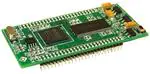
GEMexpressTM is a universal
TFT/OLED driver PCBA
GEMexpress TM
GCC-1
Data Sheet
Introduction:
It is a fast, inexpensive production solution for
adding a graphic user interface to an embedded
product. GEMexpressTM allows for greater design
flexibility and a shorter time to market. This new
hardware approach to GUI integration contains all
of Amulet’s bill of materials, which is everything
needed to drive the user interface. It just needs
to be attached to a simple display interface board
and the human interface is ready for production.
As it’s easy to integrate, Amulet sees it as the
“express” lane to production: fast, easy and cost
effective.
Features:
•
Amulet AGB75LC04-BG-E 225-ball
LFBGA Graphical OS Chip™
•
Integrated resistive 4 or 5 wire touch panel
decoder
•
Storage Capacity – 32megabit SerialFlash
for storing GUI pages
•
64megabit SDRAM (frame buffer)
•
Serial Interfaces – 3.3v UART, TWI, USB
•
Two 50 Pin Interface Connectors for LCD
signals, power and serial communication
•
Dedicated Crystal for System
•
Small and compact 1.5” x 3.0”, fits within
the outline of a 3.5” TFT.
�GCC-1
Datasheet 1.0 - 1109
Electrical Characteristic
3.1 Recommended Operating Conditions
5V
5V Current
3.2 DC Characteristics
V core Supply Current
V input Low Level
V input High Level
Pull Up Resistors
IO Output Current
Static Current Excluding Power on
Reset V core = 1.2V
Static Current Logic cells consumption,
including Power on Reset and all input
drivers V core = 1.2V
4.75V - 20V 5V Recommended
500mA
22mA @1.2V
-0.3 to 0.8V
2V to (Vcc + 0.3V )
70K to 175KOhms
8mA
600uA
30uA
�Pin Descriptions
Pin Type
I = Input
O = Output
P = Power Supply
Pin #
Signal
Type
1
5V
P
2
5V
P
3
3V
P
4
3V
P
5
GND
P
Ground
6
GND
P
Ground
7
N/C
8
N/C
9
N/C
10
N/C
11
N/C
12
N/C
5V @ 500mA
3V @ 500mA Output
13
TWI SDA
I/O
Serial Data
14
TWI SCLK
I/O
Serial Clock
15
GND
P
Ground
16
GND
P
Ground
17
COMMU TXD
O
Asynchronous Serial-Data Output
18
COMMU RXD
I
Asynchronous Serial-Data Input
19
GND
P
Ground
20
PWM2
O
Programmable clock 2
21
GND
P
Ground
22
PWM1
O
Programmable clock 1
23
P MODE
I
System Power Up Mode ( 1 = Program, 0 = Run Note:1
24
PWM0
O
25
TPC
I
Note:1 Internally pulled up. Only pull to ground
Description
Table 1. Header J1
GCC-1
Datasheet 1.0 - 1109
Programmable clock 0
Touch Panel Cal. ( 0 = Normal, 1 = CALIBRATE ) Note:1
�GCC-1
Datasheet 1.0 - 1109
Pin #
Signal
Type
26
GND
P
27
GPIO 4
I/O
28
GPIO 12
I/O
29
GPIO 3
I/O
30
GPIO15
I/O
31
GPIO 14
I/O
32
GPIO 2
I/O
33
GND
P
Ground
34
PROGU RXD
I
Asynchronous Serial-Data Input
35
PROGU TXD
O
Asynchronous Serial-Data Output
36
GND
P
Ground
37
VBUS
I
Monitor for host detection
38
DDP
I/O
39
GND
P
40
DDM
I/O
Ground
100K Programmable Pull-up
USB Device Port Data+
Ground
USB Device Port Data-
41
GND
P
Ground
42
SPI CS3
O
SPI Chip Select
43
SPI CS2
O
SPI Chip Select
44
SPI CS1
O
SPI Chip Select
45
SCLK
I/O
SPI Clock
46
MOSI
O
SPI Data Out
47
MISO
I
SPI Data In
48
GND
P
Ground
49
N/C
I
Reset Active Low
50
/RESET
Note:1 Internally pulled up. Only pull to ground
Description
Table 2. Header J1
�Pin #
Signal
Type
1
GND
P
2
R0
O
LCD Pixel Data Red
3
R1
O
LCD Pixel Data Red
4
R2
O
LCD Pixel Data Red
5
R3
O
LCD Pixel Data Red
6
R4
O
LCD Pixel Data Red
7
R5
O
LCD Pixel Data Red
8
R6
O
LCD Pixel Data Red
9
R7
O
LCD Pixel Data Red
10
GND
P
Ground
11
G0
O
LCD Pixel Data Green
12
G1
O
LCD Pixel Data Green
13
G2
O
LCD Pixel Data Green
14
G3
O
LCD Pixel Data Green
15
G4
O
LCD Pixel Data Green
16
G5
O
LCD Pixel Data Green
17
G6
O
LCD Pixel Data Green
18
G7
O
LCD Pixel Data Green
19
GND
P
Ground
20
B0
O
LCD Pixel Data Blue
21
B1
O
LCD Pixel Data Blue
22
B2
O
LCD Pixel Data Blue
23
B3
O
LCD Pixel Data Blue
24
B4
O
LCD Pixel Data Blue
O
LCD Pixel Data Blue
25
B5
Note:1 Internally pulled up. Only pull to ground
Table 3. Header J2
GCC-1
Datasheet 1.0 - 1109
Description
Ground
�GCC-1
Datasheet 1.0 - 1109
Pin #
Signal
Type
26
B6
O
LCD Pixel Data Blue
27
B7
O
LCD Pixel Data Blue
28
GND
P
Ground
29
DISP
O
Display Control Signal. LCD power ( 1 = ON, 0 = OFF)
30
OE
O
Output Enable
31
Vsync
O
TFT LCD First frame synchronization.
32
Hsync
O
Output goes active for one clock period after all the serial data for
the current line has been shifted out.
33
PC
O
LCD Drive Signal. LCD crystal polarization clock.
34
GND
P
Ground
35
A2D6
I
A2D
36
A2D5
I
A2D
37
A2D4
I
A2D
38
TOUCH X+
I
Touch Panel X+
39
TOUCH Y+
I
Touch Panel Y+
40
TOUCH X-
I
Touch Panel X-
41
TOUCH Y-
I
Touch Panel Y-
42
GND
P
Ground
43
SPI CS3
O
SPI Chip Select
44
SPI CS2
O
SPI Chip Select
45
SPI CS1
O
SPI Chip Select
46
SCLK
I/O
SPI Clock
47
MOSI
O
SPI Data Out
48
MISO
I
SPI Data In
49
GND
P
Ground
50
GND
P
Note:1 Internally pulled up. Only pull to ground
Description
Table 4. Header J2
Ground
�External Circuit Diagram
GCC-1
Datasheet 1.0 - 1109
�GCC-1
Datasheet 1.0 - 1109
Dimensions
Header 2 x 25 2mm pitch
�Tel (408) 374-4956
Fax (408) 374-4941
http://www.AmuletTechnologies.com
Sales@AmuletTechnologies.com
Support@AmuletTechnologies.com
700 Gale Drive, Suite 190
Campbell, CA 95008 USA
Disclaimer: The information in this document is provided in connection
with Amulet Technologies, LLC (Amulet) products. No license, express or
implied, to any intellectual property right is granted by this document or in
connection with the sale of Amulet products. EXCEPT AS SET FORTH IN
AMULET’S TERMS AND CONDITIONS OF SALE WHERE AMULET IS
THE SELLER, AMULET ASSUME NO LIABILITY WHATSOEVER AND
DISCLAIM ANY EXPRESS, IMPLIED OR STATUTORY WARRANTY
RELATING TO ITS PRODUCTS INCLUDING, BUT NOT LIMITED
TO, THE IMPLIED WARRANTY OF MERCHANTABILITY, FITNESS
FOR A PARTICULAR PURPOSE, OR NON-INFRINGEMENT. IN NO
EVENT SHALL AMULET BE LIABLE FOR ANY DIRECT, INDIRECT,
CONSEQUENTIAL, PUNITIVE, SPECIAL OR INCIDENTAL DAMAGES
(INCLUDING, WITHOUT LIMITATION, DAMAGES FOR LOSS AND
PROFITS, BUSINESS INTERRUPTION, OR LOSS OF INFORMATION)
ARISING OUT OF THE USE OR INABILITY TO USE THIS DOCUMENT,
EVEN IF AMULET HAS BEEN ADVISED OF THE POSSIBILITY OF
SUCH DAMAGES. Amulet makes no representations or warranties
with respect to the accuracy or completeness of the contents of this
document and reserves the right to make changes to specifications and
product descriptions at any time without notice. Amulet does not make
any commitment to update the information contained herein. Unless
specifically provided otherwise, Amulet products are not approved for use
in automotive applications, medical applications (including, but not limited
to, life support systems and other medical equipment), avionics, nuclear
applications, or other high-risk applications (e.g., applications that, if they
fail, can be reasonably expected to result in significant personal injury or
death).
GCC-1
Datasheet 1.0 - 1109
�
很抱歉,暂时无法提供与“GCC-1”相匹配的价格&库存,您可以联系我们找货
免费人工找货- 国内价格 香港价格
- 1+1197.890811+154.96547