MOP-GL24064A-BYFY-22N-3IN 数据手册
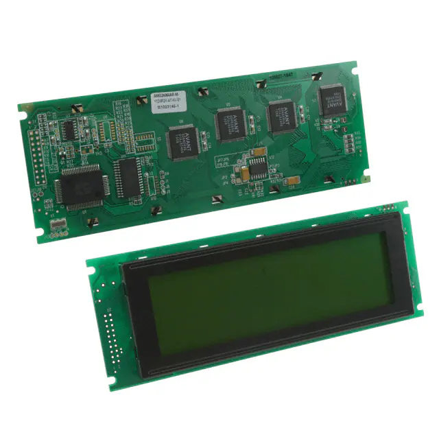
MOP-GL24064A
Parallel Display Specifications
Revision 1.0
�Revision History
Revision
1.0
0.2
0.1
1
Date
March 16, 2012
Description
Initial Release
Updates as per issue #333
Initial Draft
Author
Clark
Clark
Clark
�Contents
Revision History ............................................................................................................................................ 1
Contents ........................................................................................................................................................ 2
Features ........................................................................................................................................................ 3
Hardware ...................................................................................................................................................... 3
Drawing ..................................................................................................................................................... 3
Interface .................................................................................................................................................... 3
Instructions ................................................................................................................................................... 4
Outline ...................................................................................................................................................... 4
Instruction Table ....................................................................................................................................... 5
Timing Characteristics ............................................................................................................................... 6
Specifications ................................................................................................................................................ 7
Electrical .................................................................................................................................................... 7
Optical ....................................................................................................................................................... 7
Environmental ........................................................................................................................................... 7
Troubleshooting ............................................................................................................................................ 8
Power ........................................................................................................................................................ 8
Display ....................................................................................................................................................... 8
Communication ......................................................................................................................................... 8
Precautions ............................................................................................................................................... 8
Ordering ........................................................................................................................................................ 9
Part Numbering Scheme ........................................................................................................................... 9
Options ...................................................................................................................................................... 9
Contact .......................................................................................................................................................... 9
2
�Features
The Matrix Orbital Parallel display series offers a low cost display solution utilizing an industry standard
communication interface for simple integration into a wide variety of new and existing applications. The
Light Emitting Diode backlight with configurable brightness and voltage controlled contrast allows the
MOP Liquid Crystal Display line to offer a professional display solution for any project.
Hardware
Drawing
180.0±0.5
176.0
154.8
132.2[V.V.]
127.16[A.A.]
65.0±0.5
56.8
54.0
39.2[V.V.]
33.88[A.A.]
14.0
CL
CL
CL
CL
5.08
4-R1.75
2.5
10.0
20- 1.0
4.25
2.54
3- 1.0
0.53
0.53
10.9±0.5
0.49
0.49
4.1
5.5
16.0[MAX.]
P2.54X9=22.86
2.0
11.6
1.6±0.1
Figure 1: MOP-GL24064A Mechanical Drawing
Interface
Table 1: Display Control
Pin
1
2
3
4
5
6
7
8
9
10
19
20
3
Symbol
FGnd
VSS
VDD
V0
WR
RD
CS
C/D
NC
RST
FS
VEE
Description
Frame Ground
Ground
Supply Voltage for Logic
Supply Voltage for LCD (Contrast)
Write
Read
Chip Enable
Command/Data
No Connect
Reset
Font Select
*Negative Voltage Output
Table 2: Parallel Data and Backlight
Pin
11
12
13
14
15
16
17
18
A
K
Symbol
DB0
DB1
DB2
DB3
DB4
DB5
DB6
DB7
LED (+)
LED (-)
Description
Data bit 0
Data bit 1
Data bit 2
Data bit 3
Data bit 4
Data bit 5
Data bit 6
Data bit 7
Backlight Anode
Backlight Cathode
*Note: Offered on applicable units only
�Instructions
Outline
The MOP-GL24064A is controlled using a standard T6963 compliant controller. The display is enabled by
pulling the Chip Select (CS) pin low, communication to and from the device is controlled using the active
low Write (WR) and Read (RD) inputs, and the unit may be reset by pulling the RST line low. Using
Register Select, either the Command Register (C) or Data Register (D) is selected by toggling C/D high or
low respectively.
Before any data is read or written, the status of the display controller must be read. This is
accomplished by setting RD low, WR high, CS low, C/D high, and reading the status byte that appears on
the data lines. Each bit of the status word indicates a specific condition, outlined below.
Table 3: Status Bits
Bit
D0
D1
D2
D3
D4
D5
D6
D7
Description
Command execution capability.
Data read/write capability.
Auto mode data read capability.
Auto mode data write capability.
Unused.
Controller operation capability.
Screen peek/copy error flag.
Blink condition.
Status
0:Disabled, 1:Enabled.
0:Disabled, 1:Enabled.
0:Disabled, 1:Enabled.
0:Disabled, 1:Enabled.
Unused.
0:Disabled, 1:Enabled.
0:No Error, 1:Error.
0:Display Off, 1:Normal Display.
The first two bits, D0 and D1, should be read at the same time. In auto mode, D2 and D3 become valid
while D0 and D1 are invalid. The display should be in an enabled condition before commands or data
are transmitted. Data bytes are transferred before commands, as shown below.
Figure 2: Single Byte Command
Figure 3: Two Byte Command
4
�Instruction Table
Table 4: Parallel Instruction Table
Instruction
Set Cursor Pointer
Set Offset Register
Set Address Pointer
Set Text Home Address
Set Text Address
Set Graphic Home Address
Set Graphic Area
Set OR Mode
Set EXOR Mode
Set AND Mode
Text Attribute Mode
Internal CG ROM Mode
External CG RAM Mode
Display Off
Cursor On, Blink Off
Cursor On, Blink On
Text On, Graphic Off
Text Off, Graphic On
Text On, Graphic On
1-Line Cursor
2-Line Cursor
3-Line Cursor
4-Line Cursor
5-Line Cursor
6-Line Cursor
7-Line Cursor
8-Line Cursor
Set Data Auto Write
Set Data Auto Read
Auto Reset
Write and Increment Pointer
Read and Increment Pointer
Write and Decrement Pointer
Read and Decrement Pointer
Write and Leave Pointer
Read and Leave Pointer
Screen Peek
Screen Copy
Bit Reset
Bit Set
5
Instruction Code
DB7
0
0
0
0
0
0
0
1
1
1
1
1
1
1
1
1
1
1
1
1
1
1
1
1
1
1
1
1
1
1
1
1
1
1
1
1
1
1
1
1
DB6
0
0
0
1
1
1
1
0
0
0
0
0
0
0
0
0
0
0
0
0
0
0
0
0
0
0
0
0
0
0
1
1
1
1
1
1
1
1
1
1
DB5
1
1
1
0
0
0
0
0
0
0
0
0
0
0
0
0
0
0
0
1
1
1
1
1
1
1
1
1
1
1
0
0
0
0
0
0
1
1
1
1
DB4
0
0
0
0
0
0
0
0
0
0
0
0
0
1
1
1
1
1
1
0
0
0
0
0
0
0
0
1
1
1
0
0
0
0
0
0
0
0
1
1
DB3
0
0
0
0
0
0
0
X
X
X
X
0
1
0
X
X
0
1
1
0
0
0
0
0
0
0
0
0
0
0
0
0
0
0
0
0
0
1
0
1
DB2
0
0
1
0
0
0
0
0
0
0
0
X
X
0
X
X
1
0
1
0
0
0
0
1
1
1
1
0
0
0
0
0
0
0
1
1
0
0
B
B
DB1
0
1
0
0
0
1
1
0
0
0
1
X
X
0
1
1
X
X
X
0
0
1
1
0
0
1
1
0
0
1
0
0
1
1
0
0
0
0
I
I
DB0
1
0
0
0
1
0
1
0
0
1
1
X
X
0
0
1
X
X
X
0
1
0
1
0
1
0
1
0
1
0
0
1
0
1
0
1
0
0
T
T
Data 1
Data 2
X Address
Data
Low Address
N/A
N/A
N/A
N/A
N/A
N/A
N/A
N/A
N/A
N/A
N/A
N/A
N/A
N/A
N/A
N/A
N/A
N/A
N/A
N/A
N/A
N/A
N/A
N/A
N/A
N/A
N/A
Data
N/A
Data
N/A
Data
N/A
N/A
N/A
N/A
N/A
Y Address
0
High Address
N/A
N/A
N/A
N/A
N/A
N/A
N/A
N/A
N/A
N/A
N/A
N/A
N/A
N/A
N/A
N/A
N/A
N/A
N/A
N/A
N/A
N/A
N/A
N/A
N/A
N/A
N/A
N/A
N/A
N/A
N/A
N/A
N/A
N/A
N/A
N/A
N/A
�Timing Characteristics
Table 5: Read and Write Operation Specifications
Item
C/D Set-Up Time
C/D Hold Time
CE, RD, WR Pulse Width
Data Set-Up Time
Data Hold Time
Access Time
Output Hold Time
Symbol
Min Typ Max Unit
tCDS
100 -
ns
-
tCDH
10
ns
-
-
tCEr,tRD,tWR 80
ns
-
-
tDS
80
ns
-
-
tDH
40
ns
-
-
tACC
150
ns
-
-
tOH
10
50
ns
-
Conditions: Ta = -20℃ to 75℃, VSS = 0V, VDD = 5.0± 0.5V
Figure 4: Timing Waveform
6
�Specifications
Electrical
Table 6: Electrical Characteristics
Item
Supply Voltage For Logic
Supply Voltage For LCD (Contrast)
Input High Voltage
Input Low Voltage
Supply Current (VDD=5V)
Supply Voltage of Yellow-Green Backlight (126 Die)
Supply Current of Yellow-Green Backlight (126 Die)
Supply Voltage of White Backlight (4 Die)
Supply Current of White Backlight (4 Die)
Symbol
VDD
V0
VIH
VIL
IDD
VLED
ILED
VLED
ILED
Min
4.5
-8.7
0.7 VDD
VSS
9.0
3.8
0
3.0
0
Typ
5.0
-7.5
-
-
9.9
4.2
-
3.2
-
Max
5.5
-6.5
VDD
0.3 VDD
12.0
4.3
630
3.4
150
Unit
V
V
V
V
mA
V
mA
V
mA
Optical
θb
θf
Table 7: Display Characteristics
Item
Number of Pixels
Module dimension
View area
Active area
Dot size
Dot pitch
Duty
View direction
φ= 180°
θl
Dimension
240 Columns x 64 Rows
180.0 x 65.0 x 16.0
132.2 x 39.2
127.16 x 33.88
0.49 x 0.49
0.53 x 0.53
1/64
12 o’clock
Unit
-
mm
mm
mm
mm
mm
θr
φ= 90°
φ= 270°
φ= 0°
Figure 5: Viewing Angle Definition
Non-selected
Conition
Selected Conition
Non-selected
Conition
Intensity
10%
Table 8: Viewing Characteristics
Item
View Angle
Contrast Ratio
Response Time
Symbol
(V)θ
(H)φ
CR
T rise
T fall
Min
-20
-30
-
-
-
Typ
-
-
3
-
-
Max
35
30
-
250
250
Unit
deg
deg
-
ms
ms
90%
100%
Tr
Environmental
Table 9: Environmental Specifications
Item
Operating Temp.
Storage Temp.
Note: Maximum 90% non-condensing humidity.
7
Symbol
Top
Tstr
Tf
Figure 6: Display
Time
[positiveResponse
type]
Min
-20
-30
Max
70
80
Unit
℃
℃
�Troubleshooting
Power
For your MOP Display to function correctly, appropriate power must be applied, often as indicated by
the backlight illuminating or a darkening of the character spaces. Please refer to the power diagram
below and reference all voltages to the specifications provided.
Figure 7: Single Supply Configuration
Figure 8: Dual Supply Configuration
Display
If your display is powered successfully, the backlight or contrast should be evident. A lack of text could
be the result of a high contrast voltage, lower V0.
Communication
When communication of either text or commands is interrupted, check all data and control pins for
continuity. Finally, slow down communication and refer to timing diagrams and specifications for
proper control flow.
Precautions
•
•
•
•
•
•
Do not make extra holes in the display, modify its shape, or change the components.
Avoid applying excessive electrical or mechanical shock to the module.
Do not drop, bend, twist, or disassemble the display.
Avoid operation outside absolute maximum ratings.
Solder only to the I/O terminals provide, ensuring proper grounding.
Store in an anti-static container within a clean environment, clean carefully if necessary.
8
�Ordering
Part Numbering Scheme
Table 10: Parallel Part Numbering Scheme
MOP
1
-
G
2
L
3
240
4
64
5
A
6
-
B
7
Y
8
F
9
Y
10
-
2
11
2
12
N
13
-
3
14
I
15
N
16
Options
Table 11: Parallel Part Options
#
1
2
3
Designator
Product Line
Display Type
Screen Type
4
Display Columns
5
Display Rows
6
Display Form Factor
7
IC Package
8
LCD Glass Type
9
Polarizer Style
10
Backlight Colour
11
Viewing Angle
12
Controller
13
14
Character Set
Input Voltage
15
Temperature Range
16
Negative Voltage Generation
Options
MOP: Matrix Orbital Parallel Display
G: Graphic
L: Liquid Crystal Display
122: One Hundred Twenty-Two Pixel Columns
240: Two Hundred Forty Pixel Columns
32: Thirty-Two Pixel Rows
64: Sixty-Four Pixel Rows
128: One Hundred Twenty-Eight Pixel Rows
A: A Form Factor
B: B Form Factor
D: D Form Factor
R: R Form Factor
B: Chip on Board
B: STN Positive Blue
G: STN Positive Grey
S: Special
W: FSTN Positive
Y: STN Positive Yellow
F: Transflective
S: Special
T: Transmissive
X: Inverse Tricolour
Y: Yellow-Green
W: White
1: 6:00
2: 12:00
2: T6963 Compatible
6: SED 1520 Compatible
N: None
3: 5.0V
I: Industrial
S: Standard
N: None Provided
Y: Negative Voltage Output Provided
Contact
Sales
Support
Online
Phone: 403.229.2737
Phone: 403.204.3750
Purchasing: www.matrixorbital.com
Email: sales@matrixorbital.ca Email: support@matrixorbital.ca Support: www.matrixorbital.ca
9
�
MOP-GL24064A-BYFY-22N-3IN 价格&库存
很抱歉,暂时无法提供与“MOP-GL24064A-BYFY-22N-3IN”相匹配的价格&库存,您可以联系我们找货
免费人工找货