GTT43A-TPR-BLS-B0-H1-CU-V5 数据手册
GTT43A
Hardware Manual
Revision 1.3
PCB Revision: 2.0 or Higher
�Revision History
Revision
1.3
Date
July 22nd, 2014
1.2
1.1
1.0
May 16th, 2014
January 8th, 2014
October 24th, 2013
Description
Change to RS422 Pinout, Updated Dimensional Drawing and
Header Locations image.
Removed V3 Option
Minor Details and Formatting
Initial Release
Author
Martino
Martino
Clark
Clark
�Contents
1 Introduction ............................................................................................................................................... 1
2 Features ..................................................................................................................................................... 2
3 Ordering ..................................................................................................................................................... 3
3.1 Ordering Part Numbering Scheme ...................................................................................................... 3
3.2 Options ................................................................................................................................................ 3
3.3 Recommended Parts ........................................................................................................................... 4
Serial Communication ........................................................................................................................... 4
I2C Communication ............................................................................................................................... 4
USB Communication ............................................................................................................................. 4
Power .................................................................................................................................................... 4
Mass Storage ......................................................................................................................................... 4
4 Hardware.................................................................................................................................................... 5
4.1 Available Headers ............................................................................................................................... 5
4.2 Extended Serial Communication/Power Header ................................................................................ 6
4.3 Mini-B USB Communication Connector .............................................................................................. 6
4.1 Alternate Power Connector ................................................................................................................ 7
*Note: Do Not power the ......................................................................................................................... 7
Alternate USB Communication Header................................................................................................. 7
Drivers ................................................................................................................................................... 7
4.2 I2C Communication/Power Header ..................................................................................................... 8
4.3 RS422 Header ...................................................................................................................................... 8
4.4 Mass Storage Mini-B USB Header ....................................................................................................... 9
Alternate USB Mass Storage Header..................................................................................................... 9
Mass Storage Mode .............................................................................................................................. 9
SD Memory Card ................................................................................................................................... 9
4.5 General Purpose Outputs ................................................................................................................. 10
4.6 Keypad Header .................................................................................................................................. 10
5 Troubleshooting ....................................................................................................................................... 11
5.1 Power ................................................................................................................................................ 11
5.2 Display ............................................................................................................................................... 11
�5.3 Communication ................................................................................................................................. 11
5.4 Factory Defaults ................................................................................................................................ 11
6 Appendix .................................................................................................................................................. 12
6.1 Dimensional Drawing ........................................................................................................................ 12
6.2 Power Consumption.......................................................................................................................... 13
6.3 Environmental ................................................................................................................................... 13
6.4 Touch Specifications .......................................................................................................................... 13
6.5 Optical Characteristics....................................................................................................................... 13
6.6 ESD Performance............................................................................................................................... 13
6.7 Electrical Characteristics ................................................................................................................... 13
Absolute Maximum Ratings ................................................................................................................ 13
Communication Characteristics .......................................................................................................... 14
6.8 Defect Criteria ................................................................................................................................... 14
Display Specifications .......................................................................................................................... 14
Appearance Specifications .................................................................................................................. 14
7 Definitions ................................................................................................................................................ 15
8 Contact ..................................................................................................................................................... 15
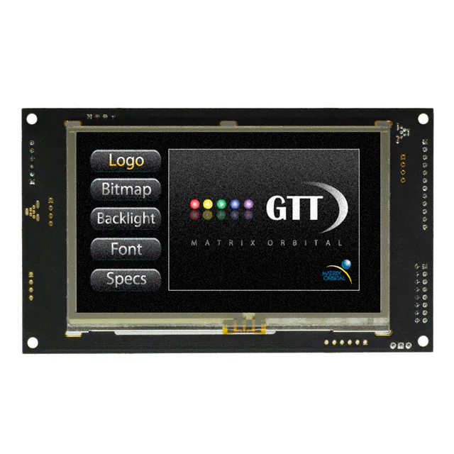
�Figure 1: The GTT43A Display
1 Introduction
The Matrix Orbital GTT43A is a full colour TFT display with an integrated touch screen, crafted to become
a crisp, controllable canvas for creativity. Utilizing an extended version of our widely used command
library and industry standard communication protocols, the customizable GTT43A series contains an
intelligent display that will quickly become the gorgeous face of your application.
1
GTT43A Hardware Manual
�2 Features
In addition to a beautiful full-colour TFT screen, seamless incorporation of a touch panel provides sleek
user input while a small piezo speaker and vibratory motor can offer audio and tactile feedback for a
completely interactive experience. Storage of fonts and bitmaps within the swappable onboard SD
memory card allows for a co-ordinated appearance in any design.
The elegant simplicity of the familiar Matrix Orbital command structure now provides updates to the
user and optional flow control for full two-way communication. Also new are animations, full-colour
graphs, automated display initialization, and field upgradeability.
Figure 2: Functional Diagram
Available flow controlled RS232 and TTL interfaces, as well as an I2C protocol provide versatile
communication schemes, while USB and RS422 versions ensure that any controller can have a beautiful
user interface. Scorching fast communication speeds, up to 256kbps in serial modes and 400kHz in I2C,
ensure important information is relayed on time.
GTT43A Hardware Manual
2
�3 Ordering
The innovative GTT43A, with all of the features mentioned above, is available in various voltage and
communication options to provide a sleek touch of creativity to any project.
3.1 Ordering Part Numbering Scheme
Table 1: Part Numbering Scheme
GTT 43 A -TPR -BLS -B1 -H1 -CU -V5
1
2 3
4
5
6
7
8
9
3.2 Options
Table 2: Display Options
#
Designator
Options
1
2
3
4
Product Type
Display Size
Screen Type
Touch
5
Backlight
6
Bezel
7
Headers
8
Protocol
9
Voltage
GTT: Graphic TFT Display
43: 4.3"
A: A Type
-TPN: No touch panel
-TPR: Resistive touch panel
-TPC: Capacitive touch panel
-BLS: Brightness < 300 Nit
-BLM: 300 Nit < Brightness < 600 Nit
-BLH: 600 Nit < Brightness < 1000 Nit
-BLD: Brightness > 1000 Nit
-B0: None
-B1: Metal
-B2: Plastic
-H0: No Connectors
-H1: Standard Connectors
-H2: Locking Connectors
-H3: Right Angle, Locking Connectors
-H4: Terminal Blocks
-CS: RS232 Model
-CT: TTL Model
-CU: USB Model
-C4: RS422 Model
-CE: Ethernet Model
-CC: CAN Model
-CI: I2C Model
-V5: 5.0V Input Voltage
-VPT: Regulated 9V-35V Input Voltage
*Note: All options may not be available, please consult www.matrixorbital.com for a list of purchasable products.
3
GTT43A Hardware Manual
�3.3 Recommended Parts
Serial Communication
The most common cable choice for the any GTT display, the Extended
Communication/ Power Cable offers a simple connection to the unit with
familiar interfaces. A DB9 and floppy power header provide all necessary
input to communicate to and power your display.
Figure 3: ESCCPC5V
I2C Communication
For a more flexible interface to the GTT, especially with the I2C protocol,
a Breadboard Cable may be used. This provides a simple four wire
connection that is popular among developers for its ease of use in a
breadboard environment.
Figure 4: BBC
USB Communication
The External Mini-B USB Cable is recommended for USB communication.
It will connect to the Mini-B style header on the unit and provide a
connection to a regular A style USB connector, commonly found on a PC.
Figure 5: EXTMUSB3FT
Power
Figure 6: PCS
The standard power cable can be used to apply power to the GTT, either
in conjunction with the ESCCPC5V cable, or via a direct connection to the
Alternate Power Header. It connects to a standard PC power supply.
Mass Storage
An External Mini-B USB Cable may also be used to access data within the
onboard SD card when removing the card itself is not possible. This
connection also provides power to the GTT and can be more convenient
than moving the SD card from one location to another.
Figure 7: EXTMUSB3FT
GTT43A Hardware Manual
4
�4 Hardware
4.1 Available Headers
Figure 8: GTT43A Header Locations
Table 3: List of Available Headers
#
1
2
3
4
5
6
7
8
9
10
11
5
Header
Extended Serial Communication & Power
USB Communication & Power
Alternate USB
I2C Communication & Power
Alternate Power
RS422 Communication & Power
Mass Storage
Alternate Mass Storage
Keypad
GPO
Mass Storage Selector
Standard Mate
ESCCPC5V, ISCCPC5V
EXTPUSB6FT
None Offered
BBC
PCS
16-30 AWG Wire
EXTPUSB6FT
None Offered
KPP4x4
None Offered
Jumper
GTT43A Hardware Manual
Population
RS232/TTL Models Only
USB Model Only
Custom Only
All Models
USB Model Only
RS422 Model Only
All Models
Custom Only
All Models
All Models
All Models
�4.2 Extended Serial Communication/Power Header
The communication/power header provides an interface for the two most common GTT43A protocols:
RS232 and TTL. With the ability to connect to a PC serial port or microcontroller and optional hardware
flow control, this is the most versatile header available on the GTT43A.
Table 4: Extended Communication/Power Pinout
Pin
6
5
4
3
2
1
Function
RTS
CTS
Gnd
Tx
Rx
Vcc
Figure 9: Extended Communication/Power Header
Voltage is applied through pins one and four of the header, please reference electrical specifications
before applying power. Pins two and three are reserved for serial transmission using either RS-232/TTL
levels, depending on what model has been ordered. Finally, pins five and six are used for optional
hardware flow control. The Serial Molex 22-04-1061 style header used can be mated to a number of
connectors, including a 22-01-1062.
4.3 Mini-B USB Communication Connector
USB protocol offers an easy connection to any host computer. The simple and widely available protocol
can be accessed using the familiar Mini-B USB connector to fulfill both communication and power needs.
Table 5: Mini USB Pinout
Pin
1
2
3
5
Function
Vcc
DD+
Gnd
Figure 10: Mini USB Connector
The USB model can be connected to virtually any USB host using the appropriate cable, and additional
power may be supplied through the alternate power header if necessary. Most commonly used with a
PC, this connection creates a virtual com port that offers a simple power solution with a familiar
communication scheme.
GTT43A Hardware Manual
6
�4.1 Alternate Power Connector
The Alternate Power Connector provides the ability to power the GTT43A using an alternate cable*.
This feature can supply additional power to the GTT that your USB connection alone cannot provide,
especially when peripherals such as the piezo buzzer, motor and GPOs are used.
Table 6: Alternate Power Pinout
Pin
1
2
3
4
Function
5V
Gnd
Gnd
NC**
Figure 11: Alternate Power Connector
The standard Tyco 171825-4 style header is particularly useful for connecting to an unmodified floppy
power cable, a 171822-4 for example, from a PC power supply for a simple bench power solution.
*Note: Do Not power the GTT43A using both USB and Alternate Power connections. When using the Alternate
Power connector move the 0 ohm resistor at R82 to R28. If you have any questions, please Contact a friendly
Matrix Orbital support representative.
**Note: When using a –VPT model, it may be desirable to input power to the GTT using the floppy power cable
12V connection. Please Contact a friendly Matrix Orbital support representative for modification details.
Alternate USB Communication Header
Some advanced applications may prefer the straight four pin connection offered through the optional
Alternate USB Header. The Alternate USB Header may be added to the USB model for an added charge
as part of a custom order. Please use the Contact section to reach Sales for additional details.
Drivers
The latest drivers are available for download in a zipped file format at www.matrixorbital.ca/drivers. To
install or update the drivers installed on your PC, locate the GTT43A in your device manager, right click
its’ icon, select Update Driver Software, and manually point to the unzipped driver file.
7
GTT43A Hardware Manual
�4.2 I2C Communication/Power Header
A dedicated I2C header is available on all GTT43A models and provides the most basic protocol
connection to the unit.
2
Table 7: I C Communication/Power Pinout
2
Figure 12: I C Communication/Power Header
Pin
1
2
3
4
Function
Vcc
SCL
SDA
Gnd
Voltage is applied through pins one and four of the header, please reference the electrical specifications
before applying power. Pins two and three are reserved for I2C clock and data signals respectively, both
of which should be pulled up to five volts using a resistance between one and ten kilohms. The Tyco
640456-4-LF style header used can be mated to a number of connectors, including Molex 22-01-3047.
4.3 RS422 Header
RS422 communication provides an industrial alternative to the standard RS232 communication protocol.
Rather than single receive and transmit lines, the RS422 model uses a differential pair for each receive
and transmit signals to reduce degradation and increase transmission lengths.
Table 8: RS422 Pinout
Pin
1
2
3
4
5
6
Figure 13: RS422 Header
Function
Vcc
Tx (A)
Inv Tx (B)
*Inv Rx (Z)
*Rx (Y)
Gnd
The six pin RS422 Header offers a power and ground connections at either end, and two differential pair
communication lines in the middle. Regular and inverted lines, labelled A/B and Z/Y, are provided for
receive and transmit signals. The standard Tyco 282834-6 style header populated is best mated to a
sized 16 to 30 on the American Wire Gauge connections that are secured via the header screws.
*Note: Changes made in PCB Rev. 2.2, prior to Rev. 2.2 Pin 4 was Rx (Y) and Pin 5 was Inv Rx (Z).
GTT43A Hardware Manual
8
�4.4 Mass Storage Mini-B USB Header
The GTT43A comes with a secondary Mini-B USB connector to access the SD memory card as a mass
storage device for easier access to the files contained on the card.
Table 9: Mass Storage USB Pinout
Pin
1
2
3
5
Function
Vcc
DD+
Gnd
Figure 14: Mass Storage USB Connector
The mass storage selector must be placed on the pins labelled “A” to use this function, please refer to
the Mass Storage Mode section for further information.
Alternate USB Mass Storage Header
Some advanced applications may prefer the straight four pin connection offered through the optional
Alternate Mass Storage Header. The Alternate Mass Storage Header may be added to the GTT43A as
part of a custom order. Please use the Contact section to reach Sales for additional details.
Mass Storage Mode
Placing a jumper on the USB mass storage selector labelled ”A”, the unit will appear to any PC as a mass
storage device when powered, giving you access to the contents of the SD memory card directly.
Please note, the speed of data transfers in mass storage mode is limited, and is only intended to be used
in situations where an external SD memory card reader is not available.
SD Memory Card
The SD Memory Card is used to store all user fonts, bitmaps, 9-slices, animations and start-up settings.
The start-up settings are stored in a binary file called AUTOEXEC. This file contains a simple stream of
characters stored just as they would be if they were sent to the display at runtime, this will store all the
commands to change the initial settings for your application. Start-up settings are stored in this location
alone; therefore, simply removing the AUTOEXEC file will restore the display to factory defaults.
Please refer to the Protocol Manual at http://www.matrixorbital.ca/manuals/GTT Series/ for a complete
list of available commands executable not only at start up but runtime as well.
9
GTT43A Hardware Manual
�4.5 General Purpose Outputs
A unique feature of the GTT43A is the ability to control relays* and other external devices using either
one of six General Purpose Outputs.
Table 10: GPO Pinout
Pin
1
2
3
4
5
6
7
8
Figure 15: GPO Header
Function
Gnd
GPO 1
GPO 2
GPO 3
GPO 4
GPO 5
GPO 6
Vcc
Pin
8
9
10
11
12
13
14
16
Function
Gnd
Gnd
Gnd
Gnd
Gnd
Gnd
Gnd
Gnd
Each can source up to 15mA of current at five volts when on, or sink 15mA at zero volts when off. The
two row, fourteen pin header can be interfaced to a number of female connectors to provide control to
any peripheral devices required.
4.6 Keypad Header
To facilitate user input, the GTT43A provides a Keypad Connector which allows a matrix style keypad of
up to twenty-five keys to be directly connected to the display module. Key presses are generated when
a short is detected between a row and a column. When a key press is generated, a character specific to
that key press is automatically sent on the Tx communication line. If the display module is running in I²C
mode, the key press will remain in the buffer until it is accessed using the display read address.
Table 11: Keypad Pinout
Figure 16: Keypad Header
Pin
1
2
3
4
5
6
Function
Gnd
Row 1
Row 2
Row 3
Row 4
Row 5
Pin
7
8
9
10
11
12
Function
Column 1
Column 2
Column 3
Column 4
Column 5
Gnd/Vcc**
The character that is associated with each key press may be altered using the “Assign Key Codes”
command. The straight twelve pin header of the Keypad Interface Connector will interface to a variety
of different devices including the Matrix Orbital KPP4x4 keypad.
*Note: If connecting a relay, be sure that it is fully clamped using a diode and capacitor in order to absorb any
electro-motive force (EMF) which will be generated.
**Note: The Ground / +5V pin is toggled by the jumper to the right of the keypad connector. Jump pads 1 & 2 for
+5V or 2 & 3 for GND.
GTT43A Hardware Manual
10
�5 Troubleshooting
5.1 Power
To function correctly, the GTT43A must be supplied with the appropriate power. If the power LED near
the top right corner of the board is not illuminated, power is not applied correctly. Try the tips below.
GTT devices have specific power requirements. Ensure the correct voltage and sufficient
current are available to your device by consulting the Power Consumption table.
Check the power cable which you are using for continuity. If you don't have an ohm meter,
try using a different power cable, if this does not help try a different power supply.
Check the power connector in use on your display. If the connector has become loose or
you are unable to resolve the issue, please use the Contact section to reach a friendly Matrix
Orbital support representative.
5.2 Display
If your display is powered successfully with an AUTOEXEC file present, the Matrix Orbital logo or user
specified screen should display briefly on start up. If this is not the case, check out these tips.
If any start-up issues are encountered, it is recommended that you remove the AUTOEXEC
file from the SD card to allow the unit to start with factory defaults.
5.3 Communication
When communication of either text or commands is interrupted, try the steps below.
First, check the communication cable for continuity. If you don't have an ohm meter, try
using a different communication cable. If you are using a PC try using a different Com Port.
In USB protocol, ensure that a connection is made to the header labelled USB, not Mass
Storage and check that the mode selection jumper is not placed on the “A” side.
In serial protocol, ensure that the host system and display module are both communicating
on the same baud rate. The default baud rate for the display module is 115,200 bps.
Match Rx from the display to the transmit pin from your host and the Tx pin to receive.
If you are communicating to the display via I²C* please ensure that the data is being sent to
the correct address. The default slave address is decimal 80 (0x50 hex).
In I2C mode, connect SDA to the data line of your controller and SCL to the clock output.
5.4 Factory Defaults
If the settings of your display become altered in a way that dramatically impacts usability, the default
settings can be restored simply by removing the AUTOEXEC file in the memory card’s root directory. This
will remove the start screen and reset the baud rate to 115,200. If the Matrix Orbital start screen is
desired, default files are available at www.matrixorbital.ca/manuals/GTT_Series/GTT_Example_Files.
*Note: I²C communication will always require pull up resistors on SCL and SDA of one to ten kilohms.
11
GTT43A Hardware Manual
�6 Appendix
6.1 Dimensional Drawing
Figure 17: GTT43A Drawing
GTT43A Hardware Manual
12
�6.2 Power Consumption
6.3 Environmental
Table 12: Required Supply Voltage
Parameter Min Typ Max Unit
Supply
Voltage
4.75 5.0 5.25 V
9.0 12.0 35.0 V
Table 14: Environmental Specifications
Remarks
Standard Voltage (V5)
Wide Voltage (VPT)
Table 13: Operating Current Draw
Parameter Min Typ Max Unit Remarks
Logic
Backlight
Piezo
Motor
GPO
0
-
290 - mA Backlight Off
100 185 mA Off, Mid, Max
100 - mA
Burst
110 - mA
Burst
- 15 mA
Each
0°C to +50°C
Operating Temperature
-20°C to +70°C
Storage Temperature
95% (T < 40°C)
Operating Relative
85%
(40°C < T < 50°C)
Humidity*
*Note: No condensation at any temperature
6.4 Touch Specifications
Table 15: Touch Screen Attributes
Hardness
Required Force
Active Area
6.5 Optical Characteristics
H
N
mm
6.6 ESD Performance
Table 16: Optical Characteristics
Table 17: ESD Resistance Data
Module Size 135.1 x 80.5 x 17.1 mm
Viewing Area 98.70 x 57.50 mm
93.04 x 53.86
mm
Active Area
480 x RGB x 272
Pixel Pattern
0.198 x 0.198
mm
Dot Pitch
2
250
cd/m
Luminance
65° Left, Right
Viewing Angle
Contrast Ratio
3.0
1.177
96.70 x 55.50
Component Value Unit
±15
kV
Serial Translator ±15
(RS232, RS422)
±8
kV
Controller
2
(I C, TTL)
55° Up, Down
400:1
±4
kV
kV
Remarks
Human Body Model
Air Gap
(IEC 1000-4-2)
Contact
(IEC 1000-4-2)
Human Body Model
6.7 Electrical Characteristics
Absolute Maximum Ratings
Table 18: GTT43A Limiting Values
Parameter
Supply Voltage
RS232 Pins
RS422 Pins
I2C/TTL pins
USB Pins
13
Min
Max
Unit
Remarks
-0.5
-0.5
-25
-13.2
-13
-0.5
-0.5
6
35
25
13.2
13
3.6
3.8
V
V
V
V
V
V
V
Standard Voltage (V5) Option
Extended Wide Voltage (VPT) Option
Input Signals
Output Signals
Inverting and Non, Input and Output Signals
SCL, SDA, Input and Output Signals
Input and Output Signals
GTT43A Hardware Manual
�Communication Characteristics
Table 19: RS232 Interface Characteristics
Min
Parameter
Input Threshold Low
0.6
Input Threshold High
Output Voltage Swing
±5.0
Input Resistance
3
Output Resistance
300
Output Short Circuit Current -
Typ Max Unit
1.2
V
1.5 2.4
V
±5.4 V
5
7
kΩ
10M Ω
±35 ±60 mA
Table 20: USB Interface Characteristics
Parameter
Min Typ Max Unit
Static Output High
Static Output Low
Input Differential Threshold
2.8
0.2
Common Mode Output Voltage 0.8
Driver Output Impedance
2
26
-
3.6
0.3
-
-
2.5
V
29
44
Ω
Table 21: I C Interface Characteristics
Table 22: TTL Interface Characteristics
Parameter
Min Typ Max Unit
Parameter
Input Threshold Low
Input Threshold High
Output Voltage Low
Output Short Circuit Current
0 1.0 V
2.3 3.3 3.6 V
0 0.4 V
- ±50 mA
Input Threshold Low
Input Threshold High
Output Voltage Low
Output Voltage High
Output Short Circuit Current
V
V
V
Min Typ Max nit
2.3
2.9
-
0
3.3
0
3
-
1.0 V
3.6 V
0.4 V
3.3 V
±50 mA
Table 23: RS422 Interface Characteristics
Parameter
Min Typ Max Unit
Input Voltage (A and B)
-7.0 - 12.0
Input Differential Threshold
-200 -125 -50
Differential Driver Output
2
3.3
Common Mode Output Voltage
- 1.65 3
Input Resistance
96
Driver Short Circuit Current Limit
- 250
Receiver Output Short Circuit Current 95
V
mV
V
V
kΩ
mA
mA
Remarks
-7V < Vin < +12V
RL = 100Ω
-7V < Vin < +12V
6.8 Defect Criteria
Display Specifications
Appearance Specifications
Table 24: Display Defect Criteria
Defect
Line
Bright
Dots
Dark
Dots
Total
Condition
Not Allowed
Red + Green + Blue
Within φ10mm Circle
Red + Green + Blue
Within φ10mm Circle
Bright Dots + Dark Dots
Table 25: Screen and Touch Defect Criteria
Criteria
N/A
≤ 3 Dots
0 Sets
≤ 3 Dots
0 Sets
≤ 3 Dots
Defect*
Condition
d
< 0.10mm
Circular
0.10mm
≤ d < 0.20mm
Objects
(Stains, Dust, Scratch,
0.20mm ≤ d < 0.25mm
Bubble, Dark/White
spot, Foreign matter)
0.25mm ≤ d < 0.30mm
W≤0.015mm
W≤0.05mm, L≤2.0mm
Linear
Objects
W≤0.03mm, L≤3.0mm
W>0.1mm, L≥1.0mm
*Note: Defects must occur in Active Area
GTT43A Hardware Manual
Critera
Allowed
≤3points
≤2points
≤1points
Allowed
≤2points
≤2points
≤1points
14
�7 Definitions
9-Slice: Graphic format used to scale bitmaps, usually rectangular, without distorting their geometry.
Nine regions define the object center, four corners, and four sides for accurate up or down scaling.
ASCII: American standard code for information interchange used to give standardized numeric codes to
alphanumeric characters.
BPS:
Bits per second, a measure of transmission speed.
GUI:
Graphical user interface.
Hexadecimal:
A base 16 number system utilizing symbols 0 through F to represent the values 0-15.
I2C:
Inter-integrated circuit protocol uses clock and data lines to communicate short distances at
slow speeds from a master to up to 128 addressable slave devices. A display is a slave device.
LSB:
Least significant bit or byte in a transmission, the rightmost when read.
MSB:
Most significant bit or byte in a transmission, the leftmost when read.
RS232: Recommended standard 232, a common serial protocol. Logic levels can be as high as +/-30V, a
high level is negative, a low is positive.
RS422: Recommended standard 422, a more robust differential pair serial protocol.
SDA: Serial data line used to transfer data in I2C protocol. This open drain line should be pulled high
through a resistor. Nominal values are between 1K and 10K Ω.
SCL:
Serial clock line used to designate data bits in I2C protocol. This open drain line should be pulled
high through a resistor. Nominal values are between 1K and 10K Ω.
TTL:
Transistor-transistor logic applied to serial protocol. Low level is 0V while high logic is 5V.
USB:
Universal Serial Bus protocol widely used in PCs.
8 Contact
Sales
Support
Online
Phone: 403.229.2737
Phone: 403.229.2737
Purchasing: www.matrixorbital.com
Email: sales@matrixorbital.ca Email: support@matrixorbital.ca Support: www.matrixorbital.ca
15
GTT43A Hardware Manual
�