0
登录后你可以
  • 下载海量资料
  • 学习在线课程
  • 观看技术视频
  • 写文章/发帖/加入社区
创作中心
发布
  • 发文章

  • 发资料

  • 发帖

  • 提问

  • 发视频

创作活动
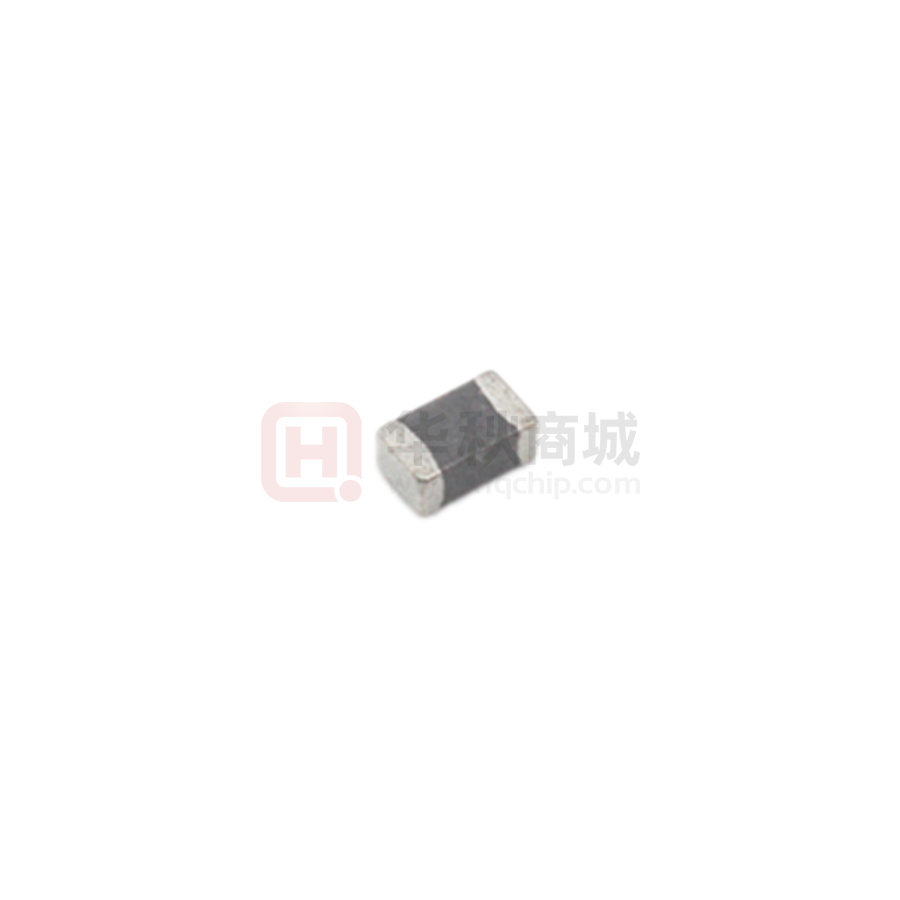
FCI2012F-R22K

FCI2012F-R22K

  • 厂商:

    TAI-TECH(台庆)

  • 封装:

    0805

  • 描述:

    信号/去耦电感 220nH 250mA ±10% 500mΩ 0805

  • 数据手册
  • 价格&库存
FCI2012F-R22K 数据手册
TAI-TECH KBM01-171100472 P1. Ferrite Chip Inductor(Lead Free) FCI2012F-SERIES ECN HISTORY LIST REV DATE DESCRIPTION APPROVED CHECKED DRAWN 楊祥忠 羅培君 張嘉玲 楊祥忠 羅培君 張嘉玲 1.0 13/06/06 變更可靠度條件 2.0 14/01/24 3.0 14/08/01 變更 Reflow 圖示 楊祥忠 羅培君 張嘉玲 3.1 14/08/01 修正包裝帶尺寸 楊祥忠 羅培君 張嘉玲 4.0 16/01/26 楊祥忠 詹偉特 張嘉玲 5.0 17/02/16 修訂 Recommended PC Board Pattern 楊祥忠 詹偉特 張嘉玲 變更電鍍錫層厚度 3.0um min.=>3.5um min. 修訂可靠度 Life Test: (Inductor) Temperature:85±2℃105±2℃. 備 註 www.tai-tech.com.tw TAI-TECH KBM01-171100472 Ferrite Chip Inductor(Lead Free) P2. FCI2012F-SERIES 1.Features 1. Monolithic inorganic material construction. 2. Closed magnetic circuit avoids crosstalk. 3. S.M.T. type. 4. Suitable for reflow soldering. 5. Shapes and dimensions follow E.I.A. spec. 6. Available in various sizes. 7. Excellent solder ability and heat resistance. 8. High reliability. 9.100% Lead(Pb) & Halogen-Free and RoHS compliant. Halogen Pb Halogen-free Pb-free 2. Dimensions Chip Size A 2.00±0.20 B 1.25±0.20 C 0.85±0.20 D 3. Part Numbering FCI 2012 F A B C A: Series B: Dimension C: Material D: Inductance E: Inductance Tolerance 1.25±0.20 0.50±0.30 Units: mm - 100 K D E LxW Lead Free Material 100=10.0uH K=±10%, M=±20% 4.Specification Tai-Tech Thickness Inductance(uH) Rated Current DCR SRF min. Test Frequency (MHz) Q (mA) max. (Ω) max. (MHz) min. Part Number C size(mm) Tolerance Test Frequency (Hz) FCI2012F-47N□ 0.85±0.20 0.047 60mV / 50M 15 50 300 0.20 320 FCI2012F-68N□ 0.85±0.20 0.068 60mV / 50M 15 50 300 0.20 280 FCI2012F-82N□ 0.85±0.20 0.082 60mV / 50M 15 50 300 0.20 255 FCI2012F-R10□ 0.85±0.20 0.10 60mV / 25M 20 25 250 0.30 235 FCI2012F-R12□ 0.85±0.20 0.12 60mV / 25M 20 25 250 0.30 220 FCI2012F-R15□ 0.85±0.20 0.15 60mV / 25M 20 25 250 0.40 200 FCI2012F-R18□ 0.85±0.20 0.18 60mV / 25M 20 25 250 0.40 185 FCI2012F-R22□ 0.85±0.20 0.22 60mV / 25M 20 25 250 0.50 170 FCI2012F-R27□ 0.85±0.20 0.27 60mV / 25M 20 25 250 0.50 150 FCI2012F-R33□ 0.85±0.20 0.33 60mV / 25M 20 25 250 0.55 145 FCI2012F-R39□ 0.85±0.20 0.39 60mV / 25M 25 25 200 0.65 135 FCI2012F-R47□ 1.25±0.20 0.47 60mV / 25M 25 25 200 0.65 125 FCI2012F-R56□ 1.25±0.20 0.56 60mV / 25M 25 25 150 0.75 115 FCI2012F-R68□ 1.25±0.20 0.68 60mV / 25M 25 25 150 0.80 105 NOTE: □:TOLERANCE K=±10%, L=±15%, M=±20% www.tai-tech.com.tw TAI-TECH KBM01-171100472 Tai-Tech Thickness Rated Current DCR SRF Part Number C size(mm) Tolerance Test Frequency (Hz) min. Test Frequency (MHz) (mA) max. (Ω) max. (MHz) min. FCI2012F-1R0□ 0.85±0.20 1.0 60mV / 10M FCI2012F-1R5□ 0.85±0.20 45 10 50 0.40 75 1.5 FCI2012F-1R8□ 0.85±0.20 1.8 60mV / 10M 45 10 50 0.50 60 60mV / 10M 45 10 50 0.60 55 FCI2012F-2R2□ 0.85±0.20 FCI2012F-2R7□ 1.25±0.20 2.2 60mV / 10M 45 10 30 0.65 50 2.7 60mV / 10M 45 10 30 0.75 45 FCI2012F-3R3□ FCI2012F-4R7□ 1.25±0.20 3.3 60mV / 10M 45 10 30 0.80 41 1.25±0.20 4.7 60mV / 10M 45 10 30 1.00 35 FCI2012F-100□ 1.25±0.20 10.0 60mV / 2M 45 2 15 1.15 24 NOTE: □:TOLERANCE ● ● Inductance(uH) Q P3. K=±10%, L=±15%, M=±20% Rated current: based on temperature rise test In compliance with EIA 595 www.tai-tech.com.tw TAI-TECH KBM01-171100472 P4. 5. Reliability and Test Condition Item Series No. Performance FCI FHI Test Condition FCH HCI -40~+105℃ (Including self-temperature rise) Operating Temperature -40~+105℃ (on board) Transportation Storage Temperature --- For long storage conditions, please see the Application Notice Agilent4291 Inductance (Ls) Agilent E4991 Agilent4287 Q Factor Refer to standard electrical characteristics list Agilent16192 DC Resistance Agilent 4338 Rated Current DC Power Supply Over Rated Current requirements, there will be some risk Temperature Rise Test 1. Applied the allowed DC current. 2. Temperature measured by digital surface thermometer. Rated Current < 1A ΔT 20℃Max Rated Current ≧ 1A ΔT 40℃Max Life test Appearance: no damage. Impedance: within±15%of initial value. Inductance: within±10%of initial value. Q:Shall not exceed the specification value. RDC:within ±15% of initial value and shall not exceed the specification value Load Humidity Appearance: no damage. Thermal shock Impedance: within±15%of initial value. Inductance: within±10%of initial value. Q:Shall not exceed the specification value. RDC:within ±15% of initial value and shall not exceed the specification value Preconditioning: Run through IR reflow for 2 times.( IPC/JEDEC J-STD-020D Classification Reflow Profiles) Temperature: 105±2℃ Applied current: rated current. Duration: 1000±12hrs. Measured at room temperature after placing for 24±2 hrs. Preconditioning: Run through IR reflow for 2 times.( IPC/JEDEC J-STD-020D Classification Reflow Profiles) Humidity: 85±2%R.H. Temperature: 85±2℃. Duration: 1000hrs Min. with 100% rated current. Measured at room temperature after placing for 24±2 hrs. Preconditioning: Run through IR reflow for 2 times.( IPC/JEDEC J-STD-020D Classification Reflow Profiles) Condition for 1 cycle Step1: -40±2℃ 30±5 min. Step2: 25±2℃ ≦0.5min Step3: +105±2℃ 30±5min. Number of cycles: 500 Measured at room temperature after placing for 24±2 hrs. Vibration Appearance:No damage. Impedance:within±15% of initial value Inductance:within±10% of initial value Q:Shall not exceed the specification value. RDC:within ±15% of initial value and shall not exceed the specification value Preconditioning: Run through IR reflow for 2 times.( IPC/JEDEC J-STD-020D Classification Reflow Profiles) Oscillation Frequency: 10 ~ 2K ~ 10Hz for 20 minutes Equipment: Vibration checker Total Amplitude:1.52mm±10% Testing Time : 12 hours(20 minutes, 12 cycles each of 3 orientations)。 Bending Appearance:No damage. Impedance:within±10% of initial value Inductance:within±10% of initial value Q:Shall not exceed the specification value. RDC:within ±15% of initial value and shall not exceed the specification value Shall be mounted on a FR4 substrate of the following dimensions: >=0805inch(2012mm):40x100x1.2mm =0805inch(2012mm):1.2mm 1GΩ More than 95% of the terminal electrode should be covered with solder. www.tai-tech.com.tw Preheat: 150℃,60sec. Solder: Sn96.5%-Ag3%-Cu0.5% Solder temperature: 245±5℃ Flux for lead free: Rosin. 9.5% Depth: completely cover the termination. Dip time: 4±1sec. TAI-TECH KBM01-171100472 P5. Item Performance Test Condition Number of heat cycles: 1 Resistance to Soldering Heat Appearance:No damage. Impedance:within±15% of initial value Inductance:within±10% of initial value Q:Shall not exceed the specification value. RDC:within ±15% of initial value and shall not exceed the specification value Temperature (°C) Time (s) Temperature ramp/immersion and emersion rate 260 ±5 (solder temp) 10 ±1 25mm/s ±6 mm/s Depth: completely cover the termination Terminal strength Preconditioning: Run through IR reflow for 2 times.( IPC/JEDEC J-STD-020D Classification Reflow Profiles) Component mounted on a PCB apply a force >0805inch(2012mm):1kg
FCI2012F-R22K 价格&库存

很抱歉,暂时无法提供与“FCI2012F-R22K”相匹配的价格&库存,您可以联系我们找货

免费人工找货
FCI2012F-R22K
  •  国内价格
  • 100+0.04428
  • 500+0.04172
  • 1000+0.03788
  • 5000+0.03276
  • 10000+0.02969

库存:3880