物料型号:MBR6035PT – MBR60100PT,由台湾半导体公司生产。
器件简介:这些是60A,35V至100V的肖特基势垒整流器,具有以下特点:
- 通过AEC-Q101认证
- 低功耗,高效率
- 防过压保护的护环
- 高浪涌电流能力
- UL认可文件编号E-326243
- 符合RoHS标准
- 根据IEC 61249-2-21无卤素
应用信息:适用于开关电源(SMPS)、适配器、监视器、直流到直流转换器、电视等。
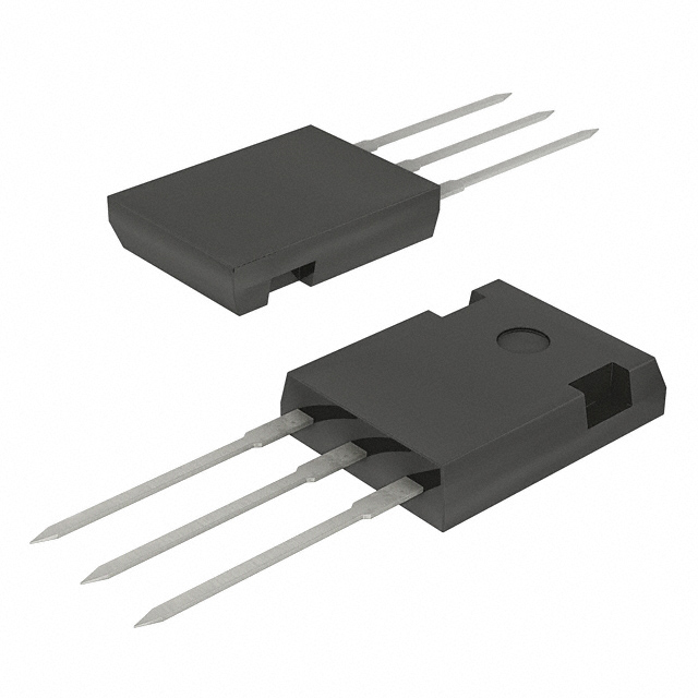
封装信息:封装类型为TO-247AD (TO-3P),封装材料满足UL 94V-0阻燃等级,端子为镀锡铅,可按J-STD-002进行焊接,符合JESD 201类2须测试,最大安装扭矩为1.13 N⋅m,极性按标记,重量约为6.10g。
参数特性:关键参数包括正向电流IF为60A,正向电压VF在30A、25°C时为0.70V(MBR6035PT和MBR6045PT),在60A、25°C时为0.93V(MBR6050PT和MBR6060PT),在额定VR下的反向电流IR在25°C时为1000μA。
引脚分配:文档中提供了引脚分配图,显示了TO-247AD (TO-3P)封装的引脚配置。
功能详解:文档提供了详细的电气规格和热性能参数,例如结到外壳的热阻ReJc为1.2°C/W,以及在不同条件下的正向电压和反向电流的典型值。
绝对最大额定值:包括结温-55至+150°C,存储温度-55至+150°C,重复峰值反向电压VRRM从35V至100V,正向电流IF为60A,浪涌峰值正向电流IFSM为420A等。
特性曲线:文档包含了正向电流降额曲线、典型结电容、典型反向特性、典型正向特性、最大非重复性正向浪涌电流和典型瞬态热阻等图表。
订购信息:提供了订购代码、封装类型和包装信息。