Data Sheet
Customer:
Product:
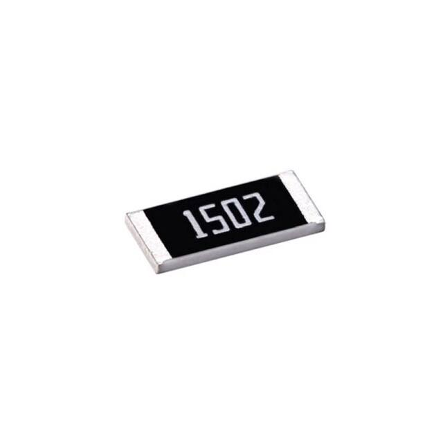
Pulse Withstanding Chip Resistor - PWR Series
Size:
0402/0603/0805/1206/1210/2010/2512
Issued Date: 15-Jun-22
Edition:
REV.D
VIKING TECH CORPORATION
光頡科技股份有限公司
VIKING TECH CORPORATION KAOHSIUNG BRANCH
光頡科技股份有限公司高雄分公司
VIKING ELECTRONICS (WUXI) CO., LTD.
光頡電子(無錫)有限公司
No.70 Guangfu N. Rd., Hukou
Township, Hsinchu County 303,
Taiwan
No.248-3, Sin-Sheng Rd., Cian-Jhen Dist., Kaohsiung,
806, Taiwan
TEL:886-3-5972931
FAX:886-3-5972935•886-3-5973494
E-mail:sales@viking.com.tw
TEL:886-7-8217999
FAX:886-7-8228229
E-mail:sales@viking.com.tw
No.22 Xixia Road, Machinery & Industry Park,
National Hi-Tech Industrial Development Zone
of Wuxi, Wuxi, Jiangsu Province, China
Zip Code:214028
TEL:86-510-85203339
FAX:86-510-85203667•86-510-85203977
E-mail:china@viking.com.tw
Produced by
(QC)
Checked
(QC)
Approved by
(QC)
15-Jun-22
15-Jun-22
15-Jun-22
Alice Hsiao
Susan Huang Susan Huang
Prepared by
(Sales)
Accepted by
(Customer)
�【PWR Series】
Pulse Withstanding Chip Resistor
Pulse Withstanding Chip Resistor – PWR Series
■Features
-Tolerance from ±0.5%~5%
-High power rating
-Excellent pulse withstanding performance
-Improved working voltage ratings
-Standard package sizes of 0402~2512
-AEC-Q200 Compliance
■Applications
-Metering (Testing/Measurement)
-Diagnostic Equipment
-Medical Devices
-Industrial Controls
-Plasma
-LCD Video Monitors
■Construction
L
D1
W
T
Alumina Substrate
External Electrode
Bottom Electrode
Resistor Layer
Top Electrode
Primary Overcoat
Edge Electrode
Secondary Overcoat
Barrier Layer
D2
■Dimensions
Type
Size
(Inch)
L
(mm)
W
(mm)
T
(mm)
D1
(mm)
D2
(mm)
PWR02
0402
1.00±0.05
0.50±0.05
0.35±0.05
0.20±0.10
0.20±0.10
Weight
(g)
(1000pcs)
0.63
PWR03
0603
1.60±0.10
0.80±0.10
0.45±0.10
0.30±0.20
0.30±0.20
2.042
PWR05
0805
2.00±0.10
1.25±0.10
0.50±0.10
0.35±0.20
0.40±0.20
4.368
PWR05 (1/2W)
0805
2.00±0.10
1.25±0.10
0.50±0.10
0.35±0.20
0.40±0.20
5.049
PWR06
1206
3.10±0.10
1.55±0.10
0.55±0.10
0.50±0.25
0.50±0.20
8.947
PWR06 (3/4W)
1206
3.10±0.10
1.55±0.10
0.55±0.10
0.50±0.25
0.50±0.20
9.541
PWR13
1210
3.10±0.10
2.60±0.15
0.55±0.10
0.50±0.25
0.50±0.20
15.959
PWR10
2010
5.00±0.10
2.50±0.15
0.55±0.10
0.60±0.25
0.50±0.20
24.241
PWR12
2512
6.35±0.10
3.10±0.15
0.55±0.10
0.60±0.25
0.50±0.20
39.448
PWR12(2W)
2512
6.35±0.20
3.15±0.15
0.60±0.10
0.60±0.25
0.60±0.20
42
www.viking.com.tw
For detail questions, contact : sales@viking.com.tw
1
Edition : REV.D
Revision: 15-Jun-2022
�【PWR Series】
Pulse Withstanding Chip Resistor
■Derating Curve
100
90
80
Power ratio(%)
70
60
50
40
30
20
10
0
-60 -50 -40 -30 -20 -10
0
10
20
30
40
50
60
70
80
90 100 110 120 130 140 150 160
Ambient Temperature(℃)
■Part Numbering
PWR
Product
Type
12
Dimensions
02: 0402
03: 0603
05: 0805
06: 1206
13: 1210
10: 2010
12: 2512
J
T
Resistance
Tolerance
D: ±0.5%
F: ±1%
J: ±5%
-: No specified
E
Packaging
Code
TCR
(PPM/°C)
T: 7”Taping Reel
V:10”Taping Reel
W:13”Taping Reel
E: ±100
F: ±200
G: ±300
4 : ±350
-: No specified
A
1001
Power
Rating
A: 1.5W
T: 1W
Q: 3/4W
U: 1/2W
G: 2/5W
O: 1/3W
V : 1/4W
W: 1/8W
X: 1/10W
P: 1/5W
S: 2W
Marking
Resistance
1001: 1KΩ
1004: 1MΩ
R0R0: 0Ω
: Standard Marking
N: No Marking
■Standard Electrical Specifications
Item
Power Rating
at 70°C
Operating
Temp. Range
Max.
Operating
Voltage
Max.
Overload
Voltage
PWR02
(0402)
1/5W
-55 ~ +155C
50V
100V
PWR03
(0603)
1/10W
-55 ~ +155C
50V
100V
Type
PWR05
(0805)
1/8W
-55 ~ +155C
150V
300V
PWR06
(1206)
1/3W
-55 ~ +155C
200V
400V
PWR13
(1210)
1/2W
-55 ~ +155C
200V
400V
PWR10
(2010)
3/4W
-55 ~ +155C
400V
800V
PWR12
(2512)
1.5W
-55 ~ +155C
500V
1000V
www.viking.com.tw
Resistance Range
±0.5%
(E24,E96)
-
TCR
(PPM/°C)
±300
100Ω-1MΩ
20.5Ω-1MΩ
±100
10Ω - 294Ω
1Ω - 294Ω
±200
300Ω - 1MΩ
10Ω - 294Ω
10Ω - 20Ω
1Ω - 20Ω
20.5Ω - 20MΩ
10Ω - 20Ω
1Ω - 20Ω
20.5Ω - 20MΩ
10Ω - 20Ω
1Ω - 20Ω
20.5Ω - 20MΩ
10Ω - 20Ω
±100
1Ω - 294Ω
300Ω - 20MΩ
For detail questions, contact : sales@viking.com.tw
2
±1%
±5%
(E24,E96)
(E24)
1Ω-20Ω
1Ω - 20Ω
20.5Ω - 20MΩ
±200
±100
±200
±100
±200
±100
±200
±100
±200
±100
Edition : REV.D
Revision: 15-Jun-2022
�【PWR Series】
Pulse Withstanding Chip Resistor
■High Power & Ultra High Power Rating Electrical Specifications
Item
Type
PWR03
(0603)
Power Rating
at 70°C
Jumper
Rated Current
1/4W
Operating
Temp. Range
Max.
Operating
Voltage
Max.
Overload
Voltage
-55 ~ +155C
75V
150V
Resistance Range
±0.5%
(E24,E96)
±1%
(E24,E96)
1Ω - 294Ω
10Ω - 294Ω
300Ω - 1MΩ
Jumper: 5A*
2/5W
0Ω(≦8mΩ)
10Ω - 294Ω
PWR05
(0805)
-55 ~ +155C
150V
±5%
(E24)
1Ω - 294Ω
1/2W *
10Ω - 294Ω
-55 ~ +155C
400V
300Ω - 1MΩ
0Ω(≦5mΩ)
-
1Ω - 20Ω
10Ω - 20Ω
1/2W
-55 ~ +155C
200V
3/4W *
500V
1000V
20.5Ω - 1MΩ
Jumper: 10A*
3/4W
PWR10
(2010)
1W
PWR12
(2512)
2W *
0Ω(≦5mΩ)
10Ω - 20Ω
PWR13
(1210)
-55 ~ +155C
200V
10Ω - 20Ω
400V
1Ω - 20Ω
±200
±100
±200
1Ω - 20Ω
±200
800V
10Ω
500V
±200
±100
20.5Ω - 1MΩ
-55 ~ +155C
±100
-
400V
20.5Ω - 1MΩ
-55 ~ +155C
±200
±100
1Ω - 20Ω
10Ω - 20Ω
-55 ~ +155C
±200
400V
20.5Ω - 1MΩ
PWR06
(1206)
±100
-
±100
1Ω - 294Ω
600V
Jumper: 6A*
PWR06
(1206)
±200
300V
300Ω - 1MΩ
PWR05
(0805)
TCR
(PPM/°C)
±100
1Ω - 10Ω
±350
1000V
10.2Ω-200K
±100
*: Ultra High Power: double side printed resistor element
Operating Voltage=√(P*R) or Max. Operating Voltage listed above, whichever is lower.
Overload Voltage=2.5*√(P*R) or Max. Overload Voltage listed above, whichever is lower.
The power rating depends on the maximum temperature of the resistive element. Due to the power dissipation of the resistor, the
temperature of the resistive element will rise depending on the condition of heat dissipation from PCB. The maximum power rating in
application only applies if the temperature of the resistive element is not exceed 155℃.
■ Viking is capable of manufacturing the optional spec based on customer’s requirement.
www.viking.com.tw
For detail questions, contact : sales@viking.com.tw
3
Edition : REV.D
Revision: 15-Jun-2022
�【PWR Series】
Pulse Withstanding Chip Resistor
■Soldering Condition (Ref. IPC/JEDEC J-STD-020 & J-STD-002)
Reflow Profiles
Profile Feature
Pb-Free Assembly
Preheat
Min. Temperature (Tsmin)
Max Temperature (Tsmax)
Preheating time (ts) from (Tsmin to Tsmax)
150 °C
200 °C
60-120 seconds
Ramp-up rate (TL to Tp)
3 °C/second max.
Liquidous temperature (TL)
Time (tL) maintained above TL
217 °C
60-150 seconds
Min. Peak temperature (Tp min)
235°C
Max. Peak temperature (Tp max)
260°C
Time (tp) within 5 °C of the specified classification temperature (Tc)
30 seconds max.
Ramp-down rate (Tp to TL)
6 °C/second max.
Time 25 °C to peak temperature
8 minutes max.
www.viking.com.tw
For detail questions, contact : sales@viking.com.tw
4
Edition : REV.D
Revision: 15-Jun-2022
�【PWR Series】
Pulse Withstanding Chip Resistor
■Environmental Characteristics
Item
Requirement
±5% and Below
Jumper
Temperature Coefficient of
Resistance (T.C.R.)
As Spec.
Short Time Overload
(1.0%+0.05Ω)
Insulation Resistance
10G
Endurance
(1.0%+0.05Ω)
0603: ≦8mΩ
0805: ≦5mΩ
1206: ≦5mΩ
0603: ≦8mΩ
0805: ≦5mΩ
1206: ≦5mΩ
(0.5%+0.05Ω)
Damp Heat with Load
Ultra High Power
*
(1.0%+0.05Ω)
0603: ≦8mΩ
0805: ≦5mΩ
1206: ≦5mΩ
Dry Heat
(0.5%+0.05Ω)
0603: ≦8mΩ
0805: ≦5mΩ
1206: ≦5mΩ
Bending Strength
(1.0%+0.05Ω)
0603: ≦8mΩ
0805: ≦5mΩ
1206: ≦5mΩ
Solderability
95% min. coverage
Resistance to Soldering Heat
Voltage Proof
(0.5%+0.05Ω)
0603: ≦8mΩ
0805: ≦5mΩ
1206: ≦5mΩ
No breakdown or flashover
Test Method
JIS-C-5201-1 4.8
IEC-60115-1 4.8
At 25C/-55C and 25C/+125C, 25C is the
reference temperature
JIS-C-5201-1 4.13
IEC-60115-1 4.13
RCWV*2.5 or Max. Overload Voltage whichever
is lower for 5 seconds
Jumper:2*Imax for 5 seconds
JIS-C-5201-1 4.6
IEC-60115-1 4.6
Max. Overload Voltage for 1 minute
JIS-C-5201-1 4.25
IEC-60115-1 4.25.1
702C, RCWV for 1000 hrs with 1.5 hrs “ON”
and 0.5 hr “OFF”
JIS-C-5201-1 4.24
IEC-60115-1 4.24
402C, 90~95% R.H., RCWV for 1000 hrs with
1.5 hrs “ON” and 0.5 hr “OFF”
JIS-C-5201-1 4.23
IEC-60115-1 4.23.2
at +155C for 1000 hrs
JIS-C-5201-1 4.33
IEC-60115-1 4.33
Bending once for 60 seconds
2010, 2512 sizes: 2mm
Other sizes: 3mm
JIS-C-5201-1 4.17
IEC-60115-1 4.17
2455C for 3 seconds
JIS-C-5201-1 4.18
IEC-60115-1 4.18
2605C for 10 seconds
JIS-C-5201-1 4.7
IEC-60115-1 4.7
1.42 times Max. Operating Voltage for 1 minute
Leaching
Rapid Change of Temperature
Individual leaching area ≦5%
JIS-C-5201-1 4.18
IEC-60068-2-58 8.2.1
Total leaching area ≦ 10%
2605C for 30 seconds
(0.5%+0.05Ω)
0603: ≦8mΩ
0805: ≦5mΩ
1206: ≦5mΩ
JIS-C-5201-1 4.19
IEC-60115-1 4.19
-55C to +155C, 5 cycles
RCWV(Rated Continuous Working Voltage)=√(P*R) or Max. Operating Voltage whichever is lower.
■Storage Temperature: 15~28C; Humidity < 80%RH
■Shelf Life: 2 years from production date.
www.viking.com.tw
For detail questions, contact : sales@viking.com.tw
5
Edition : REV.D
Revision: 15-Jun-2022
�【PWR Series】
Pulse Withstanding Chip Resistor
■Packaging
Reel Specifications & Packaging Quantity
Type
PWR02
Paper
PWR03
PWR05
PWR06
Paper
PWR13
PWR10
PWR12
Tape
Width
Reel Diameter
ΦA
(mm)
10K
8mm
7 inch
178.5±1.5
20K
8mm
10 inch
254±1.0
40K
8mm
13 inch
330±1.0
Packaging Quantity
Embossed
ΦB
(mm)
ΦC
(mm)
W
(mm)
T
(mm)
13.0±0.2
9.0±0.5
12.5±0.5
100±0.5
13.0±0.2
9.5±0.5
13.5±0.5
100±0.5
13.0±0.2
9.5±0.5
13.5±0.5
13.0±0.2
9.0±0.5
12.5±0.5
60
60
+1/-0
+1/-0
5K
8mm
7 inch
178.5±1.5
10K
8mm
10 inch
254±1.0
100±0.5
13.0±0.2
9.5±0.5
13.5±0.5
20K
8mm
13 inch
330±1.0
100±0.5
13.0±0.2
9.5±0.5
13.5±0.5
4K
12mm
7 inch
178.5±1.5
+1/-0
13.0±0.5
13.0±0.5
15.5±0.5
8K
12mm
10 inch
250±1.0
62±0.5
13.0±0.5
12.5±0.5
16.5±0.5
60
Paper Tape Specifications
Bottom Tape
Top Tape
ψ D0
E
A
F
B
T
Paper Tape
P2
P0
Direction of unreeling
W
(mm)
E
(mm)
F
(mm)
P0
(mm)
P1
(mm)
PWR02 0.65±0.10
1.15±0.10
8.00±0.2
1.75±0.1
3.50±0.05
4.00±0.10
2.00±0.05
2.00±0.05 1.50+0.1,-0
0.45±0.1
PWR03 1.10±0.10
1.90±0.1
8.00±0.2
1.75±0.1
3.50±0.05
4.00±0.10
4.00±0.05
2.00±0.05 1.50+0.1,-0
0.70±0.1
PWR05 1.60±0.10
2.40±0.2
8.00±0.2
1.75±0.1
3.50±0.05
4.00±0.10
4.00±0.05
2.00±0.05 1.50+0.1,-0
0.85±0.1
PWR06 1.90±0.10
3.50±0.2
8.00±0.2
1.75±0.1
3.50±0.05
4.00±0.10
4.00±0.05
2.00±0.05 1.50+0.1,-0
0.85±0.1
PWR13 2.90±0.10
3.50±0.2
8.00±0.2
1.75±0.1
3.50±0.05
4.00±0.10
4.00±0.05
2.00±0.05 1.50+0.1,-0
0.85±0.1
www.viking.com.tw
For detail questions, contact : sales@viking.com.tw
6
P2
(mm)
ΦD0
(mm)
B
(mm)
Type
A
(mm)
P1
Resistor
W
T
(mm)
Edition : REV.D
Revision: 15-Jun-2022
�【PWR Series】
Pulse Withstanding Chip Resistor
Embossed Plastic Tape Specifications
Top Tape
ψ D0
E
A
F
W
B
ψD11.5+0.25,-0
T
P1
Resistor
P2
P0
Direction of unreeling
Embossed Tape
B
(mm)
W
(mm)
E
(mm)
F
(mm)
P0
(mm)
P1
(mm)
P2
(mm)
ΦD0
(mm)
PWR10 2.80±0.10
5.40±0.20
12.0±0.3
1.75±0.1
5.50±0.05
4.00±0.10
4.00±0.1
2.00±0.05
1.50+0.1, -0
1.2
+0
PWR12 3.50±0.10
6.70±0.10
12.0±0.3
1.75±0.1
5.50±0.05
4.00±0.10
4.00±0.1
2.00±0.05
1.50+0.1, -0
1.2
+0
A
(mm)
Type
T
(mm)
■Marking
No Marking for 0402
0805~2512 4 digits marking for Example
Resistance
5.6Ω
97.6Ω
100Ω
2.2KΩ
10KΩ
49.9KΩ
100KΩ
1MΩ
marking
5R60
97R6
1000
2201
1002
4992
1003
1004
0603: 3 digits marking in E24
st
Example: 101=100Ω 102=1KΩ (1 and 2
E24
code
10
11
12
13
15
16
nd
18
rd
are E24 code and 3 code is multiplier)
20
22
24
27
30
33
36
39
43
47
51
56
62
68
75
82
91
1% for 0603: 3 digits marking in E96 (E96 series except E24 series)
13C
www.viking.com.tw
3 digits marking for Example: 13C=13K3Ω
68B=4K99Ω
For detail questions, contact : sales@viking.com.tw
7
68X=49.9Ω
Edition : REV.D
Revision: 15-Jun-2022
�【PWR Series】
Pulse Withstanding Chip Resistor
Marking Table
Code
E96
Code
E96
Code
E96
Code
E96
02
102
28
191
52
340
75
590
03
105
29
196
53
348
76
604
04
107
31
205
54
357
77
619
06
113
32
210
55
365
78
634
07
115
33
215
56
374
79
649
08
118
34
221
57
383
80
665
09
121
35
226
58
392
81
681
10
124
36
232
59
402
82
698
11
127
37
237
60
412
83
715
13
133
38
243
61
422
84
732
14
137
39
249
62
432
86
768
15
140
40
255
63
442
87
787
16
143
41
261
64
453
88
806
17
147
42
267
65
464
89
825
19
154
43
274
66
475
90
845
20
158
44
280
67
487
91
866
21
162
45
287
68
499
92
887
22
165
46
294
69
511
93
909
23
169
47
301
70
523
94
931
24
174
48
309
71
536
95
953
25
178
49
316
72
549
96
976
26
182
50
324
73
562
27
187
51
332
74
576
Code
A
Multiplier
10
B
0
10
C
1
10
D
2
10
E
3
10
F
4
10
G
5
10
X
6
10
-1
Y
10
-2
■Recommend Land Pattern
C
Mi
n
Type
A
(mm)
B
(mm)
C
(mm)
PWR02
0.50
0.45
0.60
PWR03
0.90
0.60
0.90
PWR05
1.20
0.70
1.30
PWR06
2.00
0.90
1.60
PWR13
2.00
0.90
2.80
PWR10
3.80
0.90
2.80
PWR12
4.90
1.00
3.40
T
B
www.viking.com.tw
A
For detail questions, contact : sales@viking.com.tw
8
Edition : REV.D
Revision: 15-Jun-2022
�【PWR Series】
Pulse Withstanding Chip Resistor
■Lightning Surge
Resistors are tested in accordance with IEC 60115-1 using both 1.2/50us and 10/700 pulse shapes. The limit of
acceptance is a shift in resistance of less than 1% from the initial value.
PWR Series 1.2/50us Lightning Surge
10000
Peak Voltage (V)
2512
2010
1210
1206
0805
0603
1000
100
10
1
10
100
1000
10000
100000
1000000
Resistance(Ω)
PWR Series 10/700us Lightning Surge
10000
2512
Peak Voltage (V)
2010
1210
1206
0805
1000
0603
100
10
1
10
100
1000
10000
100000
1000000
10000000
Resistance(Ω)
www.viking.com.tw
For detail questions, contact : sales@viking.com.tw
9
Edition : REV.D
Revision: 15-Jun-2022
�【PWR Series】
Pulse Withstanding Chip Resistor
■Pulse withstanding capacity
The limit of acceptance was a shift in resistance of less than 1% from the initial value. The power applied was subject
to the restrictions of the maximum permissible impulse voltage graph shown.
www.viking.com.tw
For detail questions, contact : sales@viking.com.tw
10
Edition : REV.D
Revision: 15-Jun-2022
�【PWR Series】
Pulse Withstanding Chip Resistor
■Continuous Pulse
The continuous load graph was obtained by applying repetitive rectangular pulses where the pulse period was
adjusted so that the average power dissipated in the resistor was equal to its rated power at 70C.
Again the limit of
acceptance was a shift in resistance of less than 1% from the initial value.
www.viking.com.tw
For detail questions, contact : sales@viking.com.tw
11
Edition : REV.D
Revision: 15-Jun-2022
�【PWR Series】
Pulse Withstanding Chip Resistor
REVISION HISTORY
REVISION DATE
Version C
CHANGE NOTIFICATION DESCRIPTION
Jun 03, 2014
-
- Environmental Characteristics updated
Version C1 Apr 21, 2016
-
- Features increase AEC-Q200 Compliance
Version C2 Jul 15, 2016
-
- Modify Storage Temperature
Version C3 Oct 13, 2017
-
- Increase High Power Specifications
Version C4 Jul 27, 2018
-
- Increase 0402 size Electrical Specifications
- Increase 0805/1206 Ultra High Power
Electrical Specifications
Version C5 May 20, 2019
-
- Modify TCR Test description
Version C6 Jan 31, 2020
-
Version C7 Mar 10, 2021
-
- Increase PWR2512 2W
- Increase 0603 / 0805/1206 High power rating
0R (Jumper)
- Modify Bending Test description
- Increase large reel packaging code
- Modify 2010 Embossed Plastic Tape B
Specification
- Modify Soldering Condition (IPC/JEDEC
J-STD-020)
Version C8 Nov 15, 2021 -
- Increase the shelf life description
Version C9 Feb 15, 2022 -
- Derating Curve changes the temperature
range
Version D
- Modify Soldering Condition
www.viking.com.tw
Jun 15, 2022
-
For detail questions, contact : sales@viking.com.tw
12
Edition : REV.D
Revision: 15-Jun-2022
�


 工商网监
湘ICP备2023018690号
工商网监
湘ICP备2023018690号
