MGV High Current Molded SMT Power Inductors
MGV0603 Series
FEATURES AND APPLICATIONS
Laird MGV series high current power inductors improve performance, reliability and power efficiency.
A lower profile benefits consumer electronics and telecom design. Products feature extremely low
DCR with greater efficiency and enable a large current in a small size. Inductors are of magnetic
shielding and molded construction and perform in operating temperatures ranging from -40 C to 125 C
including self-heating rise in temperature.
FEATURES
•
•
•
•
Magnetic shielded structure
Low DCR and high efficiency
Low profile and miniaturization
High reliability
APPLICATIONS
•
•
•
•
•
•
DC-DC Converter and Power Suppliers
LCD TV’S and Gaming Console
Tablet, Notebooks, Servers and Printers
Networking and Data storage
GPS, Set-top-box and Base stations
Smart meters and Medical instruments
PART NUMBER EXPLANATION
MGV 0603
Product series
code
Product size
code
4R7
Inductance
value code
(i.e. 4R7: 4.7
M - 10
Tolerance %
(i.e. M:
20%)
Standard
Catalog P.N
Note: Automotive grade parts are also available, a specific P.N will be assigned upon request.
Please contact laird local sales for details.
ELECTRICAL SPECIFICATIONS
• Tolerance: M: ±20% or N: ±30%
• Inductance tested at 100KHz, 1.0V
• Heat Rated Current (Irms) is defined based on temperature rise approximate 40°C without core loss
(ambient temperature 25±5°C)
• Saturation Current (Isat) is the DC current at which the inductance drops off approximately 30% from
its value without current. (ambient temperature 25±5°C)
• Operating temperature range: -40°C~+125°C (including self-heating temperature rise)
• Storage temperature range (packaging conditions): -10°C~+40°C and RH 60%(MAX.)
Note: Heat Rated Current (Irms) is tested on a typical PCB and apply a constant current in still air.
The temperature rise is dependent on the application system condition including PCB PAD pattern,
trace width and thickness and adjacent components etc. It’s suggested to verify the temperature
rise of the component under the real operation application conditions.
�Laird Performance Materials
Molded SMT Power Inductors
www.laird.com
MGV0603 Series
Rev: A
SPECIFICATION
1.MECHANICAL & DIMENSIONS
100
A
(UNIT: mm)
E
B
C
D
L
A
7.30±0.50
B
6.70±0.40
C
3.00±0.40
D
3.00±0.30
E
1.80±0.50
L
8.40 ref
G
2.50 ref
H
3.50 ref
REMARK
G
H
2.PART NUMBER NOMENCLATOR:
MGV 0603
A
B
100
C
A: Product Series.
M - 1X
D
E
D: Inductance Tolerance. (M=±20% ,N=±30%)
E: "X"=0:Standard catalog part number
"X"=1-9:Controlled customized part or different
B: Series number, part size
performance than std catalog part. And "5-9" is
C: Inductance code
for automotive grade.
3.EQUIVALENT CIRCUIT:
�Laird Performance Materials
Molded SMT Power Inductors
www.laird.com
MGV0603 Series
Rev: A
SPECIFICATION
PART NUMBER
INDUCTANCE
(uH)
MGV0603R10N-10
0.10±30%
32.50
60.00
1.2
1.7
MGV0603R22N-10
0.22±30%
23.00
40.00
2.1
2.8
MGV0603R33M-10
0.33±20%
20.00
32.00
3.5
3.9
MGV0603R47M-10
0.47±20%
17.50
26.00
4.0
4.2
MGV0603R68M-10
0.68±20%
15.50
25.00
4.8
5.5
MGV0603R82M-10
0.82±20%
13.00
24.00
6.7
8.0
MGV06031R0M-10
1.00±20%
11.00
22.00
8.3
10.0
MGV06031R5M-10
1.50±20%
9.00
18.00
13.0
15.0
MGV06032R2M-10
2.20±20%
8.00
14.00
18.0
20.0
MGV06033R3M-10
3.30±20%
6.00
13.50
24.5
30.0
MGV06034R7M-10
4.70±20%
5.50
10.00
33.5
40.0
MGV06036R8M-10
6.80±20%
4.50
8.00
54.0
60.0
MGV06038R2M-10
8.20±20%
4.00
7.50
64.0
68.0
MGV0603100M-10
10.0±20%
3.50
6.00
75.0
85.0
MGV0603150M-10
15.0±20%
3.00
4.00
107
123
MGV0603220M-10
22.0±20%
2.00
3.50
165
190
MGV0603330M-10
33.0±20%
2.00
2.50
200
240
MGV0603470M-10
47.0±20%
1.75
2.00
302
363
Irms(A) Typ. Isat(A) Typ. DCR(mΩ) Typ DCR(mΩ) Max
REMARK
GENERAL SPECIFICATION:
• Inductance tested at 100KHz, 0.25V
• Heat Rated Current (Irms) is defined based on temperature rise approximate 40°C without core loss
(ambient temperature 25±5°C)
• Saturation Current (Isat) is the DC current at which the inductance drops off approximately 30% from
its value without current. (ambient temperature 25±5°C)
• Operating temperature range: -40°C~+125°C (including self-heating temperature rise)
• Storage temperature range (packaging conditions): -10°C~+40°C and RH 60%(MAX.)
�Laird Performance Materials
Molded SMT Power Inductors
www.laird.com
MGV0603 Series
Rev: A
SPECIFICATION
Characteristics Curve
40
0.09
30
0.06
20
0.03
10
0
0
32
48
64
0.2
40
0.15
30
0.1
20
0.05
10
0
80
0
0
10
IDC(A)
40
0.30
30
0.20
20
0.10
10
0.00
0
24
32
Inductance (uH)
0.40
Temperature Rise (℃)
Inductance (uH)
50
16
50
0.80
40
0.60
30
0.40
20
0.20
10
0.00
40
0
0
6
40
0.60
30
0.40
20
0.20
10
18
IDC(A)
24
30
0
Inductance (uH)
0.80
12
18
24
30
MGV0603R82M-10
50
Temperature Rise (℃)
Inductance (uH)
MGV0603R68M-10
6
12
IDC(A)
1.00
0
50
1.00
IDC(A)
0.00
40
MGV0603R47M-10
0.50
8
30
IDC(A)
MGV0603R33M-10
0
20
Temperature Rise (℃)
16
50
1.00
50
0.80
40
0.60
30
0.40
20
0.20
10
0.00
0
6
12
IDC(A)
18
24
30
0
Temperature Rise (℃)
0
0.25
Temperature Rise (℃)
0.12
Inductance (uH)
MGV0603R22N-10
50
Temperature Rise (℃)
Inductance (uH)
MGV0603R10N-10
0.15
�Laird Performance Materials
Molded SMT Power Inductors
www.laird.com
MGV0603 Series
Rev: A
SPECIFICATION
Characteristics Curve
40
0.80
30
0.60
20
0.40
10
0.20
0.00
Inductance (uH)
1.00
Temperature Rise (℃)
10
15
20
1.60
40
1.20
30
0.80
20
0.40
10
25
0
4
40
1.50
30
1.00
20
0.50
10
0.00
0
9
12
Inductance (uH)
2.00
6
50
4.00
40
3.00
30
2.00
20
1.00
10
0
0
3
3.60
30
2.40
20
1.20
10
0.00
0
9.6
12
Inductance (uH)
40
Temperature Rise (℃)
Inductance (uH)
4.80
IDC(A)
9
12
15
MGV06036R8M-10
50
7.2
6
IDC(A)
MGV06034R7M-10
4.8
0
0.00
15
6.00
2.4
20
5.00
IDC(A)
0
16
MGV06033R3M-10
50
Temperature Rise (℃)
Inductance (uH)
MGV06032R2M-10
2.50
3
12
IDC(A)
IDC(A)
0
8
Temperature Rise (℃)
5
50
0.00
0
0
2.00
10.00
50
8.00
40
6.00
30
4.00
20
2.00
10
0.00
0
0
2
4
6
IDC(A)
8
10
Temperature Rise (℃)
Inductance (uH)
50
Temperature Rise (℃)
MGV06031R5M-10
MGV06031R0M-10
1.20
�Laird Performance Materials
Molded SMT Power Inductors
www.laird.com
MGV0603 Series
Rev: A
SPECIFICATION
Characteristics Curve
50
8.00
40
6.00
30
4.00
20
2.00
10
0.00
0
4
6
8
10
12.00
40
9.00
30
6.00
20
3.00
10
0.00
0
0
1.6
40
12.00
30
8.00
20
4.00
10
0.00
0
3
4
Inductance (uH)
16.00
2
50
20.00
40
15.00
30
10.00
20
5.00
10
0.00
5
0
0
1
40
24.00
30
16.00
20
8.00
10
0.00
0
IDC(A)
3.2
4.0
Inductance (uH)
32.00
Temperature Rise (℃)
Inductance (uH)
50
2.4
3
4
5
MGV0603470M-10
40.00
1.6
2
IDC(A)
MGV0603330M-10
0.8
8
25.00
IDC(A)
0.0
6.4
MGV0603220M-10
50
Temperature Rise (℃)
Inductance (uH)
MGV0603150M-10
20.00
1
4.8
IDC(A)
IDC(A)
0
3.2
Temperature Rise (℃)
2
50
50
50
40
40
30
30
20
20
10
10
0
0
0.5
1
1.5
IDC(A)
2
2.5
0
Temperature Rise (℃)
0
15.00
Temperature Rise (℃)
10.00
Inductance (uH)
MGV0603100M-10
Temperature Rise (℃)
Inductance (uH)
MGV06038R2M-10
�Laird Performance Materials
Molded SMT Power Inductors
www.laird.com
Recommended Soldering Conditions
1
2
3
4
5
■ For Lead-Free Application
Figure 1 . Re-flow Soldering
Within 4 sec
Reflow times: 3 times max
Figure 2 . Hand Soldering
P R E - H E A T IN G
S O L D E R IN G
NATURAL
C O O L IN G
280
TEMPERATURE C
0
230
150
O v e r 1 m in .
G r a d u a l C o o lin g
W ith in 3 s e c .
Hand solder times: 1 time max
MGV0603 Series
Rev: A
�Laird Performance Materials
Molded SMT Power Inductors
www.laird.com
MGV0603 Series
Rev: A
Reliability and Testing Conditions / Pin Type Power Inductors
SMD series(Consumer)
Item
Reference
Additional Requirements
Operating temperature
-55℃~ +125℃(Including self-temperature rise)
range
Storage temperature
and humidity range
High Temperature
Exposure
(Storage)
-10℃ to +40℃ , 60% RH Max
MIL-STD-202 Method 108
85±2℃, 168+24hours
JESD22 Method JA-104
-40℃→+85, transforming interval:20s, 100cycles
Operational Life
MIL-PRF-2
85±℃, 168+24hours
Apply maximum rated voltage and current according part drawing
External Visual
MIL-STD-883 Method 2009
Inspect device construction, marking and workmanship. Electrical
Test not required.
JESD22 Method JB-100
Verify physical dimensions to the applicable device detail
specification. Note: User(s) and Suppliers spec. Electrical Test
not required
MIL-STD-202
Method 204
10~55Hz,1.5mm,
2 hours in each 3mutually
perpendicular directions
(total of 6 hours)
Temperature Cycling
Physical Dimension
Vibration
Resistance to Soldering MIL-STD-202
Method 210
Heat
1. Max. 260±5℃,10±1s, 2 times
2.Solder Composition: Sn/3Ag/0.5Cu
Solderability
J-STD-002
245±5℃, 5±1sec, Solder: Sn/3.0Ag/0.5Cu
Electrical
Characterization
Print Spec
Parametrically test per lot and sample size requirements,
summary to show Min, Max, Mean and Standard deviation at
room as well as Min and Max Operating temperatures
AEC-Q200-005
2mm,30±1s
Board Flex
Terminal Strength(SMD) AEC-Q200-006
10N, 5S, X,Y direct
�Laird Performance Materials
Molded SMT Power Inductors
www.laird.com
MGV0603 Series
Rev: A
PACKAGING
Reel Dimension
Type A(mm) B(mm)
C(mm)
D(mm)
13'x16 16.4+2/-0 100 ± 2
13+0.5/-0.2
330
B
D
C
A
Tape Dimension
W
E
F
P
A0
B0
P2
16.0±0.3
1.75±0.1
7.50±0.1
12.00±0.1
7.00±0.1
7.70±0.1
2.0±0.1
P0
K0
t
D0
4.0±0.1 3.3±0.1 0.35±0.05 1.5Ref.
Packaging Quantity
P/N
Chip/Reel
Inner Box
Outer Box
MGV0603
1000pcs
2000pcs
4000pcs
-
-
Size
Peeling Off Force
The force peeling off cove tape is 10 to 100 grams
in the arrow direction under the following conditions
Room Temp
(℃)
Room
Humidity
Room atrn
(hPa)
Teaming
Speed
5~35
45~85
860~1060
300
※Storage Conditions
1. Temperature and humidity conditions: -10-+40℃
and 60% RH.
2. Recommended products should be used within 12 months
from the time of manufacturing.
3. The packaging material should be kept where no chlorine
or sulfur exists in the air.
4. Allowable stacking condition of Packaging box:max height 1.5m or 5 boxes stacking
�
很抱歉,暂时无法提供与“MGV0603R33M-10”相匹配的价格&库存,您可以联系我们找货
免费人工找货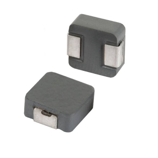


 工商网监
湘ICP备2023018690号
工商网监
湘ICP备2023018690号
