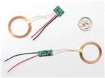
Inductive Charging Set - 5V @ 500mA max
PRODUCT ID: 1407
�DESCRIPTION
-
The squarish board with two chips on it is the transmitter (power with 9V). The
longer board is the output and you can connect that to the part of your project that
needs powering.
Inductive charging is a way of powering a device without a direct wire connection.
Most people have seen inductive charging in a rechargable electric toothbrush: you
may have noticed that you recharge it by placing it into the holder, but there's no
direct plug. These chargers work by taking a power transformer and splitting it in
half, an AC waveform is generated into one, and couples into the second coil.
This is a basic charger set, and it does work, providing 5V DC output from the
output half when the input half is powered with 9V to 12VDC. You can draw as
much as ~500mA if the coils are 2 or 3 mm apart. If you only need 100 or 200mA
you can be up 7mm apart. For 10mA draw, the coils can be up to half an inch
(12.5mm) apart. Any non-ferrous/non-conductive material (eg air, wood, leather,
plastic, paper, glass) can be used between the two coils. The material doesn't affect
the distance or efficiency. The coils do need to be fairly co-axial, try to get them to
be parallel and have the circles line up for best power-transfer. (This is why the
electric toothbrush must fit into the plastic holder, it's lining up the two coils for
best efficiency)
Because its an air-core transformer, it's fairly inefficient. Only about 40% of the
energy in shows up on the other end, but for low power or charging project. If you
draw 5V 100mA on the output side (0.5W), you'll need 0.5W * 2.5 / 9V = ~150mA
from the input end. The quiescent current is about 70mA at all time, even when the
other coil is not anywhere near by.
These are basic modules, probably used for some low cost toy. We don't have any
datasheets or specifications for them. We do see a feedback resistor divider on the
output side using 0603 SMT resistors so an advanced user could solder in different
values to turn it into a 3.3V output.
http://www.adafruit.com/product/1407
11/12/2015
�Technical Details
Diagram
Coil thickness: 1.75mm / 0.07"
PCB thickness (at tallest point): 3mm / 0.12"
Receiver weight: 5.5g
Transmitter weight 5.7g
�
很抱歉,暂时无法提供与“1407”相匹配的价格&库存,您可以联系我们找货
免费人工找货- 国内价格 香港价格
- 1+87.599821+10.98519
