Programming Guide
Programming Guide
Programming Guide
Programming Guide
Programming Guide
Programming Guide
Programming Guide
Programming Guide
C
C
T
T
A
R
R
Cooopppyyyrrriiiggghhhttt ©©© 222000111555 T
Teeerrraaasssiiiccc T
Teeeccchhhnnnooolllooogggiiieeesss IIInnnccc...A
Allllll R
Riiiggghhhtttsss R
Reeessseeerrrvvveeeddd...
�Chapter 1 System Overview 4
1.1 System Architecture
1.2 Spider Boot
4
6
1.3 Source Code
6
Chapter 2 Control Background 7
2.1 Spider Movement
2.2 Servo Motor
7
9
2.3 Command Set for Remote Control
10
Chapter 3 FPGA Quartus Project
3.1 Block Diagram
11
3.2 PW M Controller
3.3 Build Project
11
12
13
3.4 Update FPGA Configuration File to MicroSD Card
Chapter 4 Linux Spider Project 14
4.1 Linux Spider Execution File
14
4.2 Major Objects in the System
4.3 C++ Class
16
17
4.4 Build Project
18
4.5 Update Spider Execution File
18
Chapter 5 Android Spider Project
5.1 System Block Diagram
5.2 Build Project
20
5.1 Update Demo File
22
Chapter 6 Appendix
Servo Motor Connections
Revision History
Copyright Statement
19
23
23
24
24
19
13
�Chapter 1
System Overview
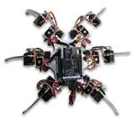
he Terasic Spider is a six-legged walking robot which is driven with 18 servo motors.
These 18 servo motors are controlled by PWM signals generated from Altera
DE0-Nano-SoC board embedded inside the Terasic Spider. The Terasic Spider itself
can be remotely controlled by a Bluetooth-enabled Android device through Bluetooth. The
app developed by Terasic can control the Terasic Spider to move in four directions and
swing based on the G-sensor on the mobile. It can even complete a dance with pre-defined
movement.
T
All the source code for the Terasic Spider is available with the kit. Users can modify the
code to improve or change the functions according to their specific applications. The source
code includes Android project, Linux application project, and Quartus project.
There is also a 2x20 GPIO expansion header available on the DE0-Nano-SoC board.
Users can connect GPIO based daughter cards to it such as camera module.
1.1 System Architecture
Figure 1-1 shows the system block diagram of the Spider Robot. The system consists of
three parts:
4
Spider Development
Guide
www.terasic.com
November 26, 2015
� FPGA Bitstream: soc_system.rbf
Linux Spider Program: spider
Android Application: terasic_spider.apk
The major function of the FPGA bitstream file is to provide PWM controller to control the rotation of the 18 servo motors. The rotation angle of each servo motor is controlled by the
PWM signal. The FPGA controls the 18 servo motors from the 18 PWM controllers.
The Linux Spider program is running on Linux on Altera SoC. The main function of this
program is to perform spider movement by the 18 PWM controller on the FPGA side to
control the 18 servo motors. The other mainfunction of this program is to provide remote
control accessibility based on Bluetooth SPP (Serial Port Profile). It can receive spider
control command from a Bluetooth enabled Android device and perform corresponding
actions such as moving forward and backward. The Linux should be built with Bluetooth
stack enabled to support Bluetooth and an external USB Bluetooth dongle is required.
The main function of the Android Spider Program is to let users remotely control the spider
through Bluetooth. The Spider program on the Android device receives users’ request from
its control GUI and it will send corresponding commands to the Linux Application Program
on DE0-Nanos-SoC. The command set is proprietary and it is defined by Terasic.
Figure 1-1 System block diagram of the Spider Robot
5
Spider Development
Guide
www.terasic.com
November 26, 2015
�1.2 Spider Boot
The spider system is configured to boot from the
MicroSD card on DE0-Nano-SoC. The Linux system,
Linux Spider program, and the FPGA bitsream file are
all stored in the MicroSD card. The FPGA bitstream file
named soc_system.rbg is located in the first partition of the
MicroSD card, which is expected to be in FAT partition. The
spider execution program named spider is located in the /home/root
directory under the Linux file system.
When Linux boots with MSEL[4:0] = 00000, the bootloader will configure the FPGA with the
FPGA bitstream file named soc_system.rbf. The spider launch script is added into the
Linux init scripts /etc/initab to start the spider execution file automatically when Linux starts
to load the application process after the kernel is loaded.
1.3 Source Code
The project source codes for these three demos are all included in the Spider System CD,
which is available on http://cd-spider.terasic.com. The corresponding folder locations of the
project source codes are shown in Table 1-1.
Project
Table 1-1 Project Location
Type
Folder Location
FPGA Spider Project Verilog Program\DE0_NANO_SOC_SPIDER
Linux Spider Project C++ Program\DE0_NANO_SOC_SPIDER_LINUX_APP
Android Spider Project Java Program\DE0_NANO_SOC_SPIDER_ANDROID
6
Spider Development
Guide
www.terasic.com
November 26, 2015
�Chapter 2
Control Background
T
his chapter gives the background for controlling the serve motor, spider movement,
and the proprietary command set used for remote communication between the
Android Spider Program and Linux Spider Program.
2.1 Spider Movement
The spider movement is based on the Tripod Gain – the spider always has three foots in
contact with the ground at all times. This will keep the spider balanced on the ground.
The six legs of the spider are grouped into Red and Blue, as shown in Figure 2-2. When
the spider moves, it moves legs from B group first, as shown in Figure 2-3. It will then move
legs in R group, as shown in Figure 2-4. The spider can move forward or backward by
moving legs of group R and B interchangeably.
Figure 2-2 Spider legs are grouped into R and B
7
Spider Development
Guide
www.terasic.com
November 26, 2015
�Figure 2-3 Spider moves legs in group B
Figure 2-4 Spider moves legs in group R
8
Spider Development
Guide
www.terasic.com
November 26, 2015
�2.2 Servo Motor
The servo motor MG996R, as shown in Figure 2-5, is used on the spider. MG996 has three
pins, as shown in Figure 2-6. The Red and Brown pins are power pins. The Orange pin is
the PWM pin, which is used to control the rotation angle. The rotation angle of this servo
motor is specified by the pulse width of PWM (Pulse Width Modulation) signal, as shown in
Figure 2-7. The servo controllers send PWM signals continuously to the servo motors and
alter the pulse with to change the rotation angle of servo motors. Note that it takes time for
the servo motor to rotate to the desired angel, so users need to make sure the rotation is
complete before sending the next rotating signals.
Figure 2-5 Servo motor with model MG996R
Figure 2-6 Pinout of servo motor MG996R
9
Spider Development
Guide
www.terasic.com
November 26, 2015
�Figure 2-7 Pulse width determines the rotation angle
2.3 Command Set for Remote Control
Android Spider program can remote control the spider based on pre-defined command set,
as shown in Table 2-1. The Command is sent from Android device to DE0-Nano-SoC.
Command
ATFW
ATBW
ATTR
ATTL
ATTR=
ATTL=
ATSP=
ATTTL
ATTTR
ATTTF
ATTTB
ATTTN
ATALL
Table 2-1 Command Set
Description
Forward
Backward
Turn Right 90 degree
Turn Left 90 degree
Turn Right with specified angle
Turn Left with specified angle
Set movement speed
Body tilt left
Body tilt right
Body tilt forward
Body tilt backward
Body tilt recovery
Demo mode
10
Spider Development
Guide
www.terasic.com
November 26, 2015
�Chapter 3
FPGA Quartus Project
T
his chapter describes the main function of FPGA Quartus project. It provides 18
PWM controllers for the Linux Application program to control the rotation angle of the
18 servo motors on the spider. Altera HPS IP is used to establish a bridge between
FPGA and HPS/ARM for the Linux Application program to access these controllers.
3.1 Block Diagram
Figure 3-1 shows the block diagram of FPGA Quartus project for the Spider. The project is
created in Qsys. The PWM controllers designed by Teraisc in Qsys are used to control the
18 servo motors. The PIO controllers for LED[6:0] and KEY[1:0] in Qsys are also included
and connected to the HPS, so the HPS/ARM can access these peripherals. The LED[7] is
connected to a counter as a system heartbeat. When the FPGA is configured with this
Quartus Project, LED[7] will blink.
11
Spider Development
Guide
www.terasic.com
November 26, 2015
�Figure 3-1 Block diagram of the Spider FPGA project
3.2 PWM Controller
It is crucial for the PWM controller not to send the final PWM immediately for the servo
motor to rate smoothly with adjustable speed. The PWM controller sends a series of PWM
with various pulse for the servo to rotate from the current angle to the desired angle in
several steps with desired speed. The controller is configured with its internal register. It
has three registers, as shown Table 3-1. The TOTAL_DUR register is used to setup the
PWM cycle time with tick count unit. The tick is 1/50MHz second in this project. The
HIGH_DUR register is used to setup the high-duration of PWM signal with tick count unit.
The CONTROL_STATUS register is used to setup the rotation speed and indicate whether
the final PWM signal for the desired angle has been sent out. Please do not update the
HIGH_DUR register value until the final PWM is sent out for servo to move smoothly and
correctly.
Offset
0
1
2
Table 3-1 Registers in PWM controller
Register Name
Write
TOTAL_DUR
HIGH_DUR
CONTROL_STATUS
Set the PWM cycle time
Set the PWM high-duration time
Set the rotation speed
Read
Get the PWM cycle time
Get the PWM high-duration time
Bit0 indicates the final PWM is sent
12
Spider Development
Guide
www.terasic.com
November 26, 2015
�The PWM controller is implemented as a custom Qsys component to make it easily
connected to the HPS in Qsys. The source code of PWM controller is located in the
ip\spider folder under the Quartus project.
3.3 Build Project
Here is the project information:
Project Creator: Quartus 14.0
Project Location: Program/DE0_NANO_SOC_SPIDER under system CD
Project Name: DE0_Nano_SoC_golden_top
Launch Quartus and open the project. After compilation, DE0_Nano_SoC_golden_top.sof
will be generated under the project folder. Because the .rbf file format is required for HPS to
configure FPGA, Terasic provides a batch file for translation from .sof to .rbf file.
Please copy the generated DE0_Nano_SoC_golden_top.sof to the sof_to_rbf folder under
the Quartus project. Execute the batch file “sof_to_rbf.bat” under the sof_to_rbf folder and a
soc_system.rbf will be generated in the sof_to_rbf folder.
3.4 Update FPGA Configuration File to MicroSD Card
Please browse the MicroSD card in Windows, as shown in Figure 3-2, to replace the FPGA
configuration file named soc_system.rbf in the MicroSD card. Delete the original
soc_system.rbf, and copy your soc_system.rbf into the MicroSD card. When Linux boots up,
the bootloader will read the contents of soc_system.rbf and configure the FPGA
accordingly.
Figure 3-2 Contents of MicroSD card when browsing in Windows
13
Spider Development
Guide
www.terasic.com
November 26, 2015
�Chapter 4
Linux Spider Project
T
his chapters describes the Linux spider project, which is a Linux C+ project, built by
Altera SoC Kit. The main function of this Linux Spider project is to perform spider
movement by controlling the 18 PWM controller on the FPGA side to control the 18
servo motors. The other main function of this program is to provide remote control
accessibility based on Bluetooth SPP (Serial Port Profile). It can receive spider control
command from a Bluetooth enabled Android device and perform corresponding actions
such as moving forward and backward. The Linux should be built with Bluetooth stack
enabled to support Bluetooth and an external USB Bluetooth dongle is required.
4.1 Linux Spider Execution File
The Linux Spider execution file is automatically executed when Linux boots up, as shown in
Figure 4-1.
14
Spider Development
Guide
www.terasic.com
November 26, 2015
�Figure 4-1 Spider execution file is executed
The execution file is located in the directory /home/root directory under the Linux file system,
as shown in Figure 4-2.
Figure 4-2 Location of Spider execution file
The spider execution script is added into the init scrip file under the directory /etc/inittab, as
shown in Figure 4-3, for it to be executed automatically when the Linux system boots up.
15
Spider Development
Guide
www.terasic.com
November 26, 2015
�Figure 4-3 Contents of the inittab file
4.2 Main Objects in the System
The Linux Spider project is written in C++. Figure 4-4 shows the main objects in the system.
The CBtSppCommand object is used to receive the spider action command from the
Android Spider program running on Android device. This object is running in a separated
thread. The thread checks whether there is a coming command in polling method. The
received commands are pushed into the CQueueCommand object. For the spider action
command details, please refer to chapter 2.
16
Spider Development
Guide
www.terasic.com
November 26, 2015
�The main program will check the CQueueCommand whether there any queue command. If
there are queue command, it will retrieve the command from the CQueueCommand object,
and control CSpider object to perform associated action. Besides, the main program polls
the CPIO_BUTTON object to check whether users press KEY1 button on the
DE0-Nano-SoC. If yes, it will control Spider object to perform a dancing demonstrating.
Figure 4-4 Major objects in the system
4.3 C++ Class
Table 4-1 the C++ class defined in the project.
Class
CSpider
CSpiderLeg
CMotor
BtSppCommand
BtSpp
CQueueCommand
CQueue
CPIO_BUTTON
CPIO_LED
Table 4-1 C++ class defined in the Spider project
Function Description
Implementation Files
Provide function to perform robot spider
actions such as move forward and backward.
Contain six CSpiderLeg objects.
Control the rotation angle of the three joints in
a robot leg.
Contains three CMotor objects.
Rotation control for a servo motor.
It will control the PWM controllers from FPGA
side to perform required angle rotation.
Parse the raw data coming from Bluetooth.
Derive from the CBtSpp class.
Provide Bluetooth SPP service based on the
RFCOMM Bluetooth stack in Linux kernel.
Queue received Bluetooth command
Provide queue function
Query the status of buttons from HPS side of
DE0-Nano-SoC
Control the LEDs from HPS side of
DE0-Nano-SoC
CSpider.cpp/h
CSpiderLeg.cpp/h
CMotor.cpp/h
BtSppCommand.cpp/h
BtSpp.cpp/h
QueueCommand.cpp/h
Queue.cpp/h
PIO_BUTTON.cpp/h
PIO_LED.cpp/h
17
Spider Development
Guide
www.terasic.com
November 26, 2015
�4.4 Build Project
Altera SoC EDS (Embedded Design Suite) is required to compile this project. Please follow
the steps below to compile the project.
1.
2.
3.
4.
5.
6.
Make sure Altera SoC EDS v14.1 is installed on the host PC.
Copy the Linux Spider project into the local hard disk.
Launch Altera “SoC EDS Command Shell”
Type “cd” command in the command shell to change the current directory to the
project location
Type “make” to build the project, as shown in Figure 4-5
The “spider” binary file will be generated in the project directory if the compilation is
successful.
Figure 4-5 Type ‘make’ to build the project
4.5 Update Spider Execution File
Copy the generated “spider” binary file to the directory /home/root directory under the
de0-nano-soc Linux file system to update the Spider execution file.
18
Spider Development
Guide
www.terasic.com
November 26, 2015
�Chapter 5
Android Spider Project
T
he Android Spider project is a Java-based project built by Eclipse. The main function
of the Android Spider project is to receive users’ input from the GUI and send
commands to the spider robot through Bluetooth. The Android device should equity
with Classical Bluetooth capacity for running this Bluetooth-based application.
5.1 System Block Diagram
Figure 5-1 The three objects in the system
The development of Android application must follow the lifecycle of Android activity. For
more information about the lifecycle of Android activity, please refer to
http://developer.android.com/reference/android/app/Activity.html. There are three UI
objects used in the demo. Figure 5-1 shows these objects in the system. When these
objects are triggered by users, the command will be sent out to the Bluetooth receiver on
the spider robot through a function named SendMessage. The SeekBar object is used to
19
Spider Development
Guide
www.terasic.com
November 26, 2015
�adjust the movement speed of the spider robot. It will send out command when the
movement speed is changed via the seek bar on the GUI. The Gyro (TextView) can display
the gyro data gathered from the mobile on the mobile dynamically. The ImageView is used
as button and it’s triggered when users press forward, backward, left, right, or the demo
mode button.
5.2 Build Project
Both Android SDK and Eclipse ADT Plugin must be installed to complete the installation for
this project prior to the development of Android. For more settings about the API 17 used in
this demo, please refer to Figure 5-2.
Figure 5-2 Edit device
There are many Android SDK versions to be chosen from and the version 4.2.2 (API 17)
must be installe. For more details about the installation, please refer to:
http://developer.android.com/sdk/installing/installing-adt.html
The project folder has to be imported prior to the start of building the project. Choose File
Import Android Existing Android Code Into Workspace from the menu.
20
Spider Development
Guide
www.terasic.com
November 26, 2015
�Press Next and browse to the project folder under the root directory. Click the Finish button.
The default project setting in Eclipse tool is Build Automatically, as shown in Figure 5-3.
21
Spider Development
Guide
www.terasic.com
November 26, 2015
�Figure 5-3 The default project setting is Built Automatically
5.1 Update Demo File
Before the demo file can be downloaded to Android mobile through Eclipse tool, the Debug
mode must be enabled to allow the installation from an unknown source. The
corresponding driver also needs to be installed on the host PC. Right-click on the project
folder and select Run AS -> Android Application to download the demo file to Android
mobile, as shown in Figure 5-4.
Figure 5-4 Update demo file
22
Spider Development
Guide
www.terasic.com
November 26, 2015
�Chapter 6
Appendix
Servo Motor Connections
Mapping Table
Leg
Motor
Index
GPIO
Index
Right-
Right-
Right-
Left-
Left-
Left-
front
middle
back
front
middle
back
0
1
2
3
4
5
6
7
8
9
10
11
12
13
14
15
16
17
9
10
11
17
16
15
14
13
12
2
1
0
18
19
20
21
22
23
23
Spider Development
Guide
www.terasic.com
November 26, 2015
�Revision History
V1.0
Version
Change Log
Initial Version
Copyright Statement
Copyright © 2015 Terasic Inc. All rights reserved.
Spider Development
Guide
24
www.terasic.com
November 26, 2015
�