Ultra Compact
Chip Antenna
Data Guide
�Table of Contents
1
1
2
2
2
3
3
4
4
5
6
8
9
10
12
13
Description
Features
Applications
Ordering Information
Electrical Specifications
Footprints
Pin Configuration
Theory of Operation
Layout Considerations
Microstrip Details
Assembly Considerations
Test Boards
VSWR Graphs
Tape Dimensions
Reel Dimensions
Mismatch Conversion Table
�Ultra Compact Chip Antenna
Data Guide
Description
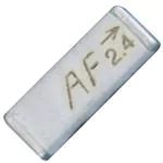
The exciting ANT-***-CHP family is among the world’s
smallest high-performance chip antennas. They are
ideal for embedding in wireless products including
Bluetooth, 802.11, Home RF, ZigBee and other
popular standards. These tiny antennas use advanced
Low Temperature Co-fired Ceramic (LTCC) technology
and proprietary elements to achieve superior size and
performance characteristics. The entire family is compatible with hand and reflow-assembly.
Excellent electrical specifications, stability,
and outstanding cost-effectiveness make
2.4
CHP Series antennas the
logical choice
for a wide variety of applications.
2.4
Figure 1: 2.4GHz Dimensions
xxx
Features
•
•
•
•
•
•
•
•
•
•
•
•
Incredibly compact SMD package
Superior LTCC technology
50Ω characteristic impedance
Low loss
Wide bandwidth
Favorable linear polarization
> Unity gain
No external matching required
Highly stable over temperature & time
Hand and reflow-assembly compatible
RoHS compliant
Cost-effective
– 1 –
Figure 2: 868MHz and 916MHz Dimensions
2.45GHz
868MHz
916MHz
Figure 3: Actual Sizes
Revised 8/8/12
�Applications
•
•
•
•
•
Footprints
Bluetooth
802.11
ZigBee
Wireless PCMCIA cards
Telemetry
•
•
•
•
Data collection
Industrial process monitoring
Compact wireless products
External antenna elimination
Ordering Information
0.130"
0.100"
0.040"
0.040"
Ordering Information
Figure 7: 868MHz and 916MHz Footprint
Figure 6: 2.4GHz Footprint
Part Number
Description
ANT-868-CHP-x
868Mhz Chip Antenna
ANT-916-CHP-x
916MHz Chip Antenna
ANT-2.45-CHP-x
2.45GHz Chip Antenna
Pin Configuration
x = "T" for tape/reel, "B" for bulk
1
All parts are RoHS compliant.
Standard reel is 3,000pcs. (868/916MHz), 1,500pcs. (2.45GHz)
Quantities less than reel size are supplied in bulk.
Figure 8: Pin Configuration
2.4
2
Pin Descriptions
Figure 4: Ordering Information
Pin Number
Electrical Specifications
Specifications
Parameter
0.630"
0.260"
2.45GHz
868MHz
916MHz
6.5(L) x 2.2(W) x
1.0(H)
16.0(L) x 3.0(W) x
1.7(H)
16.0(L) x 3.0(W) x
1.7(H)
–40 to +85°C
–40 to +85°C
–40 to +85°C
LTCC
LTCC
LTCC
Center Frequency
2.45GHz
868MHz
916MHz
Bandwidth
180MHz
10MHz
10MHz
Description
1
Feed Termination
This pin connects to the transmitter or receiver.
2
Solder Termination
This pin is soldered down for physical support only. There is no
electrical connection.
Physical
Dimensions (mm)
Operating/Storage Temp
Construction
Figure 9: Pin Configurations
Electrical
Wavelength
Pattern
Polarization
VSWR
Maximum Gain
Impedance
Power Handling
¼-wave
¼-wave
Omni-directional
Omni-direction
¼-wave
Omni-directional
Linear
Linear
Linear
≤2.0 (Max.)
≤2.0 (Max.)
≤2.0 (Max.)
+0.5dBi
+0.5dBi
+0.5dBi
50Ω
50Ω
50Ω
3W (Max.)
3W (Max.)
3W (Max.)
Figure 5: Ordering Information
– 2 –
– 3 –
�Theory of Operation
Microstrip Details
The CHP Series antennas utilize Low Temperature Cofired Ceramic (LTCC)
technology to embed the antenna element into a ceramic substrate.
Advances in this technology have resulted in materials that are extremely
stable over time and temperature, producing an antenna that is highly
reliable across a wide range of applications. The high-frequency characteristics of this technology enable exceptional performance in a very small
package. The construction techniques for LTCC devices lends itself well to
favorable pricing in high volume.
A transmission line is a medium whereby RF energy is transferred from
one place to another with minimal loss. This is a critical factor, especially in
high-frequency products like Linx RF modules, because the trace leading to the module’s antenna can effectively contribute to the length of
the antenna, changing its resonant bandwidth. In order to minimize loss
and detuning, some form of transmission line between the antenna and
the module should be used unless the antenna can be placed very close
(
很抱歉,暂时无法提供与“ANT-2.45-CHP-T”相匹配的价格&库存,您可以联系我们找货
免费人工找货