ANT-2.4-JJB-xx
Data Sheet
by
Product Description
7.0 mm
(0.28")
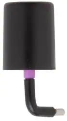
The JJB Series packs near the performance of a
conventional monopole into an incredibly compact
quarter-inch (7mm) diameter package. These
antennas are ideal for any OEM application
requiring a compact, cosmetically attractive,
low-cost antenna solution. The antenna features
a through-hole feedline that can attach directly
to a user’s PCB. Internal or external mounting is
possible.
9.0 mm
(0.35")
17.6 mm
(0.69")
8.6 mm
(0.34")
Features
•
•
•
•
•
•
•
2.0 mm
(0.08")
Very low cost
Ultra-compact package
Easily concealed internally
Good for internal or external mounting
Excellent performance
Omni-directional pattern
Use with plastic* enclosures
1.0 mm
(0.04")
14.5 mm
(0.57")ANT-916-JJB-RA
ANT-916-JJB-RA
*Requires proximity ground plane
No or
ground
ground plane
tracesplane or traces
under the antenna
under the antenna
No
5.5 mm
(0.22")
Electrical Specifications
Center Frequency:
2.45GHz
Recom. Freq. Range: 2390–2480MHz
Wavelength:
¼-wave
VSWR:
≤ 2.0 typical at center
Peak Gain:
RA: 3.3dBi
ST: –1.5dBi
Impedance: 50-ohms
Connection:
Direct solder
Oper. Temp. Range:
–40°C to +90°C
1.0 mm
(0.04")
Socket
Socket or plated
hole or plated hole
5.5 mm
(0.22") Ground
plane on bottom
Ground plane
on bottom
layer for counterpoise
layer for counterpoise
50-ohm
50-ohm microstrip
line microstrip line
Recommended Mounting
Right Angle
Straight
No ground plane
or traces under the
antenna
RA electrical specifications and plots measured on a 3.81 cm x
8.38 cm (1.50" x 3.30") ground plane
ST electrical specifications and plots measured on a 8.89 cm x
8.89 cm (3.50" x 3.50") ground plane
1.91 mm (0.075")
plated hole
Ground plane on
bottom layer for
counterpoise
Ordering Information
ANT-2.4-JJB-RA (Right-Angle)
ANT-2.4-JJB-ST (Straight)
50-ohm
microstrip line
–1–
Revised 4/11/16
�Counterpoise
Quarter-wave or monopole antennas require an associated ground plane
counterpoise for proper operation. The size and location of the ground
plane relative to the antenna will affect the overall performance of the
antenna in the final design. When used in conjunction with a ground
plane smaller than that used to tune the antenna, the center frequency
typically will shift higher in frequency and the bandwidth will decrease.
The proximity of other circuit elements and packaging near the antenna
will also affect the final performance. For further discussion and guidance
on the importance of the ground plane counterpoise, please refer to Linx
Application Note AN-00501: Understanding Antenna Specifications and
Operation.
VSWR Graph
VSWR
3:1
1.403
1.307
Reflected Power
25%
2:1
11%
1:1
0%
CENTER 2.450GHz ST
CENTER 2.450GHz RA
SPAN 200.000MHz
What is VSWR?
The Voltage Standing Wave Ratio (VSWR) is a measurement of how well
an antenna is matched to a source impedance, typically 50-ohms. It is
calculated by measuring the voltage wave that is headed toward the load
versus the voltage wave that is reflected back from the load. A perfect
match will have a VSWR of 1:1. The higher the first number, the worse the
match, and the more inefficient the system. Since a perfect match cannot
ever be obtained, some benchmark for performance needs to be set. In
the case of antenna VSWR, this is usually 2:1. At this point, 88.9% of the
energy sent to the antenna by the transmitter is radiated into free space
and 11.1% is either reflected back into the source or lost as heat on
the structure of the antenna. In the other direction, 88.9% of the energy
recovered by the antenna is transferred into the receiver. As a side note,
since the “:1” is always implied, many data sheets will remove it and just
display the first number.
How to Read a VSWR Graph
VSWR is usually displayed graphically versus frequency. The lowest point
on the graph is the antenna’s operational center frequency. In most cases,
this will be different than the designed center frequency due to fabrication
tolerances. The VSWR at that point denotes how close to 50-ohms the
antenna gets. Linx specifies the recommended bandwidth as the range
where the typical antenna VSWR is less than 2:1.
–2–
Data Sheet ANT-2.4-JJB-xx
by
�
很抱歉,暂时无法提供与“ANT-2.4-JJB-RA”相匹配的价格&库存,您可以联系我们找货
免费人工找货- 国内价格
- 1+56.13840
- 200+22.39920
- 400+21.65400
- 1000+21.28680