Datasheet
CW-RCL Series
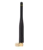
916 MHz Right-Angle Whip Antenna
The 916-CW-RCL antenna is designed for sub-1
GHz and low-power, wide-area (LPWA) applications
including LoRaWAN® and ISM band applications in
the 902 MHz to 930 MHz band.
The right-angle rotating design of the 916-CW-RCL
antenna allows for the antenna to be positioned for
optimum performance.
The 916-CW-RCL is available with an SMA plug
(male pin) or RP-SMA plug (female socket) connector
for FCC Part 15 compliant applications.
Features
Applications
• Performance at 902 MHz to 930 MHz
― VSWR: ≤ 1.8
― Peak Gain: 4.2 dBi
― Efficiency: 72%
• Compact size
― 97.7 mm x 18.7 mm x 10.5 mm
• Rotating base allows for optimal positioning
• SMA plug (male pin) or RP-SMA plug (female
socket)
• Low-power, wide-area (LPWA) applications
― LoRaWAN®
― WiFi HaLow™
• Internet of Things (IoT) devices
• Smart Home networking
― Security systems
― Home weather stations
• Remote sensing, monitoring and control
― Security systems
― Industrial machinery
― AMR (automated meter reading)
Ordering Information
Part Number
Description
ANT-916-CW-RCL-SMA
916 MHz right-angle whip antenna with SMA plug (male pin)
ANT-916-CW-RCL
916 MHz right-angle whip antenna with RP-SMA plug (female socket)
Available from Linx Technologies and select distributors and representatives.
�ANT-916-CW-RCL-ccc
Datasheet
Electrical Specifications
ANT-916-CW-RCL
Frequency Range
VSWR (max)
Peak Gain (dBi)
Average Gain (dBi)
Efficiency (%)
Polarization
Radiation
Max Power
Wavelength
Electrical Type
Impedance
Connection
Operating Temperature Range
Weight
Dimensions
916 MHz
902 MHz to 930 MHz
1.8
4.2
-1.5
72
Linear
Omnidirectional
5W
1/4-wave
Monopole
50 Ω
SMA plug (male pin) or RP-SMA plug (female socket)
-20 °C to +85 °C
12.5 g (0.44 oz)
97.7 mm x 18.7 mm x 10.5 (3.80 in x 0.74 in x 0.41 in)
Electrical specifications and plots measured with a 102 mm x 102 mm (4.0 in x 4.0 in) reference ground plane.
Packaging Information
The CW-RCL series antennas are packaged, 50 pcs in a clear plastic bag, 500 pcs per inner box, and 2000
pcs per export box. Distribution channels may offer alternative packaging options.
Product Dimensions
Figure 1 provides dimensions of the ANT-916-CW-RCL. The rotating base allows for continuous positioning
through 360 degrees even while installed.
97.7 mm
(3.80 in)
360° Rotation
18.7 mm
(0.74 in)
Ø10.5 mm
(0.41 in)
Ø6.0 mm
(0.20 in)
Figure 1. ANT-916-CW-RCL Antenna Dimensions
2
97.72
3.8
�Datasheet
ANT-916-CW-RCL-ccc
Counterpoise
1/4-Wave monopole antennas require an associated ground plane counterpoise for proper operation. The
size and location of the ground plane relative to the antenna will affect the overall performance of the antenna
in the final design. When used in conjunction with a ground plane smaller than that used to tune the antenna,
the center frequency typically will shift higher in frequency and the bandwidth will decrease. The proximity of
other circuit elements and packaging near the antenna will also affect the final performance.
For further discussion and guidance on the importance of the ground plane counterpoise, please refer to Linx
Application Note, AN-00501: Understanding Antenna Specifications and Operation.
Antenna Orientation
The ANT-916-CW-RCL is characterized on the edge of a 102 mm x 102 mm ground plane as shown in
Figure 2. This orientation, represents the most common orientation in end-product use.
Figure 2. ANT-916-CW-RCL on Evaluation PCB
3
�ANT-916-CW-RCL-ccc
Datasheet
VSWR
5
930
902
Figure 3 provides the voltage standing wave ratio (VSWR) across the antenna bandwidth. VSWR describes
the power reflected from the antenna back to the radio. A lower VSWR value indicates better antenna
performance at a given frequency. Reflected power is also shown on the right-side vertical axis as a gauge of
the percentage of transmitter power reflected back from the antenna.
VSWR
4
30
3
20
2
10
1
0
900 902 904 906 908 910 912 914 916 918 920 922 924 926 928 930 932
Frequency (MHz)
Figure 3. ANT-916-CW-RCL VSWR
Reflected Power (%)
40
Return Loss
0
930
902
Return loss (Figure 4), represents the loss in power at the antenna due to reflected signals. Like VSWR, a
lower return loss value indicates better antenna performance at a given frequency.
-2
Return Loss (dB)
-4
-6
-8
-10
-12
-14
-16
-18
-20
4
900
902
904
906
908
910
912
914 916 918 920 922
Frequency (MHz)
Figure 4. ANT-916-CW-RCL Return Loss
924
926
928
930
932
�Datasheet
ANT-916-CW-RCL-ccc
Peak Gain
5
930
902
The peak gain across the antenna bandwidth is shown in Figure 5. Peak gain represents the maximum
antenna input power concentration across 3-dimensional space, and therefore peak performance at a given
frequency, but does not consider any directionality in the gain pattern.
Peak Gain (dBi)
0
-5
-10
-15
-20
900
902
904
906
908
910
912
914 916 918 920 922
Frequency (MHz)
Figure 5. ANT-916-CW-RCL Peak Gain
924
926
928
930
932
Average Gain
5
930
902
Average gain (Figure 6), is the average of all antenna gain in 3-dimensional space at each frequency,
providing an indication of overall performance without expressing antenna directionality.
Average Gain (dBi)
0
-5
-10
-15
-20
900
902
904
906
908
910
912
914 916 918 920 922 924
Frequency (MHz)
Figure 6. ANT-916-CW-RCL Antenna Average Gain
926
928
930
932
5
�ANT-916-CW-RCL-ccc
Datasheet
Radiation Efficiency
100
930
902
Radiation efficiency (Figure 7), shows the ratio of power delivered to the antenna relative to the power
radiated at the antenna, expressed as a percentage, where a higher percentage indicates better performance
at a given frequency.
90
80
Efficiency (%)
70
60
50
40
30
20
10
0
6
900
902
904
906
908
910
912
914 916 918 920 922 924 926
Frequency (MHz)
Figure 7. ANT-916-CW-RCL Antenna Radiation Efficiency
928
930
932
�Datasheet
ANT-916-CW-RCL-ccc
Radiation Patterns
Radiation patterns provide information about the directionality and 3-dimensional gain performance of the
antenna by plotting gain at specific frequencies in three orthogonal planes. Antenna radiation patterns are
shown in Figure 8 using polar plots covering 360 degrees. The antenna graphic at the top of the page
provides reference to the plane of the column of plots below it. Note: when viewed with typical PDF viewing
software, zooming into radiation patterns is possible to reveal fine detail.
XZ-Plane Gain
YZ-Plane Gain
XY-Plane Gain
902 MHz to 930 MHz (916 MHz)
34
35
33
32
31
30
29
28
36 5
0
-5
-10
-15
-20
-25
-30
-35
-40
-45
-50
1
2
3
4
34
5
33
6
32
7
31
8
27
26
30
9
29
10
28
11
27
12
25
13
24
14
23
15
22
21
20
19
18
XZ-Plane Gain
17
16
35
36 5
0
-5
-10
-15
-20
-25
-30
-35
-40
-45
-50
1
2
3
4
34
5
33
6
32
7
31
8
26
30
9
29
10
28
11
27
12
25
13
24
14
23
21
20
19
18
17
36 5
0
-5
-10
-15
-20
-25
-30
-35
-40
-45
-50
1
2
3
4
5
6
7
8
9
10
11
26
12
13
25
24
15
22
35
16
YZ-Plane Gain
14
23
15
22
21
20
19
18
17
16
902.0
915.0
930.0
XY-Plane Gain
Figure 8. ANT-916-CW-RCL Radiation Patterns
7
�ANT-916-CW-RCL-ccc
Datasheet
Website: http://linxtechnologies.com
Linx Offices: 159 Ort Lane, Merlin, OR, US 97532
Phone:
+1 (541) 471-6256
E-MAIL: info@linxtechnologies.com
Linx Technologies reserves the right to make changes to the product(s) or information contained herein without notice. No liability is assumed as a result of their use
or application. No rights under any patent accompany the sale of any such product(s) or information.
Wireless Made Simple is a registered trademark of Linx Acquisitions LLC. LoRaWAN is a registered trademark of Semtech Corporation. Other product and brand
names may be trademarks or registered trademarks of their respective owners.
Copyright © 2020 Linx Technologies
All Rights Reserved
Doc# DS20220-80ANT
�
很抱歉,暂时无法提供与“ANT-916-CW-RCL”相匹配的价格&库存,您可以联系我们找货
免费人工找货