Datasheet
ANT-DB1-RAF
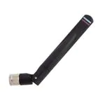
Hinged Blade WiFi 6/5/4 Antenna
The ANT-DB1-RAF is a dipole, blade-style antenna
for WiFi 6/5/4 applications in the 2.4 GHz and 5 GHz
bands and WiFi 6E in the 6 GHz band.
The hinged design allows for the antenna to be
positioned for optimum performance and reduces
the potential for damage from impact compared to a
fixed whip design.
The ANT-DB1-RAF antenna is available with an SMA
plug (male pin), or RP-SMA plug (female socket)
connector.
Features
Applications
• Performance at 2.4 GHz to 2.485 GHz
― VSWR: ≤ 1.8
― Peak Gain: 4.1 dBi
― Efficiency: 76%
• Performance at 5.150 GHz to 5.850 GHz
― VSWR: ≤ 1.7
― Peak Gain: 5.1 dBi
― Efficiency: 94%
• Compact size
― Height: 103.7 mm (4.08 in)
― Diameter: 11.2 mm (0.44 in)
• Rotating hinge design with detents for straight,
45 degree and 90 degree positioning
• SMA plug (male pin) or RP-SMA plug (female
socket) connection
• WiFi/WLAN coverage
― WiFi 6E (802.11ax)
― WiFi 6 (802.11ax)
― WiFi 5 (802.11ac)
― WiFi 4 (802.11n)
― 802.11b/g
• 2.4 GHz ISM applications
― Bluetooth®
― ZigBee®
• U-NII bands 1-8
• Internet of Things (IoT) devices
• Smart Home networking
― Sensing and remote monitoring
― Wireless vending
― Security
Ordering Information
Part Number
Description
ANT-DB1-RAF-SMA
WiFi 6/WiFi 6E blade-style antenna with SMA plug (male pin)
ANT-DB1-RAF-RPS
WiFi 6/WiFi 6E blade-style antenna with RP-SMA plug (female socket)
Available from Linx Technologies and select distributors and representatives.
�ANT-DB1-RAF-ccc
Datasheet
Table 1. Electrical Specifications
ANT-DB1-RAF
Frequency Range
VSWR (max.)
Peak Gain (dBi)
Average Gain (dBi)
Efficiency (%)
Polarization
Radiation
Wavelength
ISM/WiFi
2400 MHz to 2485 MHz
1.8
4.1
-1.4
76
Linear
Omnidirectional
1/2-wave
WiFi/U-NII 1-3
5150 MHz to 5850 MHz
1.7
5.1
-0.6
94
Impedance
Electrical Type
Max Power
WiFi 6E
5925 MHz to 7125 MHz
6.1
4.8
-2.0
72
50 Ω
Dipole
5W
Electrical specifications and plots measured in free space with antenna straight.
Table 2. Mechanical Specifications
ANT-DB1-RAF
Connection
Dimensions
Weight
Operating Temp. Range
RP-SMA plug (female socket) or SMA plug (male pin)
103.7 mm x Ø11.2 mm (4.08 in x Ø0.44 in)
12.7 g (0.45 oz)
-40 °C to +80 °C
Product Dimensions
Figure 1 provides dimensions of the ANT-DB1-RAF antenna. The antenna whip can be tilted 90 degrees,
and has a detent at 45 degrees enabling the antenna to be oriented in any direction. The rotating base
allows for continuous positioning through 360 degrees even while installed.
103.7 mm
(4.08 in)
Ø11.2 mm
(0.44 in)
Full 360° Rotation
30.3 mm
(1.19 in)
84.6 mm
(3.33 in)
0°, 45°, 90°
Figure 1. ANT-DB1-RAF Antenna Dimensions
Packaging Information
The ANT-DB1-RAF antenna is packaged in a plastic bag in quantities of 50. Bags are placed in cartons of
200. Distribution channels may offer alternative packaging options.
2
�ANT-DB1-RAF-ccc
Datasheet
Antenna Orientation
The ANT-DB1-RAF antenna is characterized in two antenna orientations as shown in Figure 2. The
free space antenna straight orientation characterizes use of an antenna attached to an enclosuremounted connector. Although the antenna is a dipole not requiring a ground plane for function, the
second characterizaton with an adjacent ground plane (102 mm x 102 mm) provides insight into antenna
performance when attached directly to a printed circuit board mounted connector. The two orientations
represent the most common end-product use cases.
Straight, Free Space without ground plane
On edge of ground plane, bent 90 degrees
Figure 2. ANT-DB1-RAF Antenna Evaluation Orientations
3
�ANT-DB1-RAF-ccc
Datasheet
Straight, Free Space
The charts on the following pages represent data taken with the antenna in free space, with straight
orientation, as shown in Figure 3
Figure 3. ANT-DB1-RAF Antenna Straight, Free Space (Straight)
VSWR
40
5
30
4
3
20
2
10
1
0
2300 2650 3000 3350 3700 4050 4400 4750 5100 5450 5800 6150 6500 6850 7200
Frequency (MHz)
Figure 4. ANT-DB1-RAF Antenna VSWR, Straight
4
Reflected Power (%)
50
6
VSWR
7125
5850
5925
5150
7
2400
2485
Figure 4 provides the voltage standing wave ratio (VSWR) across the antenna bandwidth. VSWR describes
the power reflected from the antenna back to the radio. A lower VSWR value indicates better antenna
performance at a given frequency. Reflected power is also shown on the right-side vertical axis as a gauge
of the percentage of transmitter power reflected back from the antenna.
�ANT-DB1-RAF-ccc
Datasheet
Return Loss
7125
5850
5925
5150
0
2400
2485
Return loss (Figure 5), represents the loss in power at the antenna due to reflected signals. Like VSWR, a
lower return loss value indicates better antenna performance at a given frequency.
Return Loss (dB)
-5
-10
-15
-20
-25
-30
2300 2650 3000 3350 3700 4050 4400 4750 5100 5450 5800 6150 6500 6850 7200
Frequency (MHz)
Figure 5. Return Loss for ANT-DB1-RAF, Straight
Peak Gain
7125
5850
5925
5150
10
2400
2485
The peak gain across the antenna bandwidth is shown in Figure 6. Peak gain represents the maximum
antenna input power concentration across 3-dimensional space, and therefore peak performance, at a
given frequency, but does not consider any directionality in the gain pattern.
Peak Gain (dBi)
5
0
-5
-10
-15
2300 2650 3000 3350 3700 4050 4400 4750 5100 5450 5800 6150 6500 6850 7200
Frequency (MHz)
Figure 6. Peak Gain for ANT-DB1-RAF, Straight
5
�ANT-DB1-RAF-ccc
Datasheet
Average Gain
7125
5850
5925
5150
10
2400
2485
Average gain (Figure 7), is the average of all antenna gain in 3-dimensional space at each frequency,
providing an indication of overall performance without expressing antenna directionality.
Average Gain (dBi)
5
0
-5
-10
-15
2300 2650 3000 3350 3700 4050 4400 4750 5100 5450 5800 6150 6500 6850 7200
Frequency (MHz)
Figure 7. Antenna Average Gain for ANT-DB1-RAF, Straight
Radiation Efficiency
7125
5850
5925
5150
100
2400
2485
Radiation efficiency (Figure 8), shows the ratio of power delivered to the antenna relative to the power
radiated at the antenna, expressed as a percentage, where a higher percentage indicates better
performance at a given frequency.
90
80
Efficiency (%)
70
60
50
40
30
20
10
0
2300 2650 3000 3350 3700 4050 4400 4750 5100 5450 5800 6150 6500 6850 7200
Frequency (MHz)
Figure 8. Antenna Radiation Efficiency for ANT-DB1-RAF, Straight
6
�ANT-DB1-RAF-ccc
Datasheet
Radiation Patterns
Radiation patterns provide information about the directionality and 3-dimensional gain performance of the
antenna by plotting gain at specific frequencies in three orthogonal planes. Antenna radiation patterns for
a straight orientation are shown in Figure 9 using polar plots covering 360 degrees. The antenna graphic
above the plots provides reference to the plane of the column of plots below it. Note: when viewed with
typical PDF viewing software, zooming into radiation patterns is possible to reveal fine detail.
Radiation Patterns - Straight
XZ-Plane Gain
YZ-Plane Gain
XY-Plane Gain
2400 MHz to 2485 MHz (2450 MHz)
34
35
33
32
31
30
29
28
36 5
0
-5
-10
-15
-20
-25
-30
-35
-40
-45
-50
1
2
3
4
34
5
33
6
32
7
31
8
27
26
30
9
29
10
28
11
27
12
25
21
20
19
17
18
2
3
4
34
5
6
32
7
31
8
30
9
29
10
28
11
27
12
24
21
XZ-Plane Gain
20
19
18
17
1
2
3
4
5
6
7
8
9
10
26
12
13
25
24
15
22
16
36 5
0
-5
-10
-15
-20
-25
-30
-35
-40
-45
-50
11
14
23
35
33
13
15
22
1
25
14
23
36 5
0
-5
-10
-15
-20
-25
-30
-35
-40
-45
-50
26
13
24
35
14
23
16
15
22
21
YZ-Plane Gain
20
19
18
17
16
2400 MHz
2460 MHz
2500 MHz
XY-Plane Gain
5150 MHz to 5850 MHz (5500 MHz)
34
35
33
32
31
30
29
28
36 5
0
-5
-10
-15
-20
-25
-30
-35
-40
-45
-50
1
2
3
4
34
5
33
6
32
7
31
8
27
26
30
9
29
10
28
11
27
12
25
13
24
14
23
15
22
21
20
19
18
XZ-Plane Gain
17
16
35
36 5
0
-5
-10
-15
-20
-25
-30
-35
-40
-45
-50
1
2
3
4
34
5
33
6
32
7
31
8
26
30
9
29
10
28
11
27
12
25
13
24
14
23
15
22
21
20
19
18
17
YZ-Plane Gain
16
35
36 5
0
-5
-10
-15
-20
-25
-30
-35
-40
-45
-50
1
2
3
4
5
6
7
8
9
10
11
26
12
25
13
24
14
23
15
22
21
20
19
18
17
16
5140 MHz
5500 MHz
5860 MHz
XY-Plane Gain
7
�ANT-DB1-RAF-ccc
Datasheet
Radiation Patterns - Straight
5925 MHz to 7125 MHz (6530 MHz)
34
35
33
32
31
30
29
28
36 5
0
-5
-10
-15
-20
-25
-30
-35
-40
-45
-50
1
2
3
4
34
5
33
6
32
7
31
8
27
26
30
9
29
10
28
11
27
12
25
13
24
14
23
15
22
21
20
19
18
XZ-Plane Gain
17
16
35
36 5
0
-5
-10
-15
-20
-25
-30
-35
-40
-45
-50
1
2
3
4
34
5
33
6
32
7
31
8
26
30
9
29
10
28
11
27
12
25
13
24
14
23
15
22
21
20
19
18
17
YZ-Plane Gain
16
35
36 5
0
-5
-10
-15
-20
-25
-30
-35
-40
-45
-50
2
3
4
5
6
7
8
9
10
11
26
12
25
13
24
14
23
15
22
21
20
19
18
17
XY-Plane Gain
Figure 9. Radiation Patterns for ANT-DB1-RAF Antenna, Straight
8
1
16
5920 MHz
6540 MHz
7140 MHz
�ANT-DB1-RAF-ccc
Datasheet
Edge of Ground Plane, Bent 90 Degrees
The charts on the following pages represent data taken with the antenna oriented at the edge of the ground
plane, bent 90 degrees (Edge-Bent), as shown in Figure 10.
Figure 10. ANT-DB1-RAF Antenna on Edge of Ground Plane, Bent 90 Degrees (Edge-Bent)
VSWR
40
5
30
4
3
20
2
10
Reflected Power (%)
50
6
VSWR
7125
5850
5925
5150
7
2400
2485
Figure 11 provides the voltage standing wave ratio (VSWR) across the antenna bandwidth. VSWR describes
the power reflected from the antenna back to the radio. A lower VSWR value indicates better antenna
performance at a given frequency. Reflected power is also shown on the right-side vertical axis as a gauge
of the percentage of transmitter power reflected back from the antenna.
1
0
2300 2650 3000 3350 3700 4050 4400 4750 5100 5450 5800 6150 6500 6850 7200
Frequency (MHz)
Figure 11. ANT-DB1-RAF Antenna VSWR, Edge-Bent
9
�ANT-DB1-RAF-ccc
Datasheet
Return Loss
7125
5850
5925
5150
0
2400
2485
Return loss (Figure 12), represents the loss in power at the antenna due to reflected signals. Like VSWR, a
lower return loss value indicates better antenna performance at a given frequency.
Return Loss (dB)
-5
-10
-15
-20
-25
-30
2300 2650 3000 3350 3700 4050 4400 4750 5100 5450 5800 6150 6500 6850 7200
Frequency (MHz)
Figure 12. Return Loss for ANT-DB1-RAF, Edge-Bent
Peak Gain
7125
5850
5925
5150
10
2400
2485
The peak gain across the antenna bandwidth is shown in Figure 13. Peak gain represents the maximum
antenna input power concentration across 3-dimensional space, and therefore peak performance, at a
given frequency, but does not consider any directionality in the gain pattern.
Peak Gain (dBi)
5
0
-5
-10
-15
2300 2650 3000 3350 3700 4050 4400 4750 5100 5450 5800 6150 6500 6850 7200
Frequency (MHz)
Figure 13. Peak Gain for ANT-DB1-RAF, Edge-Bent
10
�ANT-DB1-RAF-ccc
Datasheet
Average Gain
7125
5850
5925
5150
10
2400
2485
Average gain (Figure 14), is the average of all antenna gain in 3-dimensional space at each frequency,
providing an indication of overall performance without expressing antenna directionality.
Average Gain (dBi)
5
0
-5
-10
-15
2300 2650 3000 3350 3700 4050 4400 4750 5100 5450 5800 6150 6500 6850 7200
Frequency (MHz)
Figure 14. Antenna Average Gain for ANT-DB1-RAF, Edge-Bent
Radiation Efficiency
7125
5850
5925
5150
100
2400
2485
Radiation efficiency (Figure 15), shows the ratio of power delivered to the antenna relative to the power
radiated at the antenna, expressed as a percentage, where a higher percentage indicates better
performance at a given frequency.
90
80
Efficiency (%)
70
60
50
40
30
20
10
0
2300 2650 3000 3350 3700 4050 4400 4750 5100 5450 5800 6150 6500 6850 7200
Frequency (MHz)
Figure 15. Antenna Radiation Efficiency for ANT-DB1-RAF, Edge-Bent
11
�ANT-DB1-RAF-ccc
Datasheet
Radiation Patterns
Radiation patterns provide information about the directionality and 3-dimensional gain performance of the
antenna by plotting gain at specific frequencies in three orthogonal planes. Antenna radiation patterns for an
“edge-bent” orientation are shown in Figure 16 using polar plots covering 360 degrees. The antenna graphic
above the plots provides reference to the plane of the column of plots below it. Note: when viewed with
typical PDF viewing software, zooming into radiation patterns is possible to reveal fine detail.
Radiation Patterns - Edge-Bent
XZ-Plane Gain
YZ-Plane Gain
XY-Plane Gain
2400 MHz to 2485 MHz (2450 MHz)
34
35
33
32
31
30
29
28
36 5
0
-5
-10
-15
-20
-25
-30
-35
-40
-45
-50
1
2
3
4
34
5
33
6
32
7
31
8
27
26
30
9
29
10
28
11
27
12
25
21
20
19
17
18
2
3
4
34
5
6
32
7
31
8
30
9
29
10
28
11
27
12
24
16
21
XZ-Plane Gain
20
19
18
17
1
2
3
4
5
6
7
8
9
10
26
12
13
25
24
15
22
36 5
0
-5
-10
-15
-20
-25
-30
-35
-40
-45
-50
11
14
23
35
33
13
15
22
1
25
14
23
36 5
0
-5
-10
-15
-20
-25
-30
-35
-40
-45
-50
26
13
24
35
14
23
16
15
22
21
YZ-Plane Gain
20
19
18
17
16
2400 MHz
2460 MHz
2500 MHz
XY-Plane Gain
5150 MHz to 5850 MHz (5500 MHz)
34
35
33
32
31
30
29
28
36 5
0
-5
-10
-15
-20
-25
-30
-35
-40
-45
-50
1
2
3
4
34
5
33
6
32
7
31
8
27
26
13
14
23
15
22
21
20
19
18
XZ-Plane Gain
12
30
9
29
10
28
11
27
12
25
24
17
16
35
36 5
0
-5
-10
-15
-20
-25
-30
-35
-40
-45
-50
1
2
3
4
34
5
33
6
32
7
31
8
26
30
9
29
10
28
11
27
12
25
13
24
14
23
15
22
21
20
19
18
17
YZ-Plane Gain
16
35
36 5
0
-5
-10
-15
-20
-25
-30
-35
-40
-45
-50
1
2
3
4
5
6
7
8
9
10
11
26
12
25
13
24
14
23
15
22
21
20
19
18
17
XY-Plane Gain
16
5140 MHz
5500 MHz
5860 MHz
�ANT-DB1-RAF-ccc
Datasheet
Radiation Patterns - Edge-Bent
5925 MHz to 7125 MHz (6530 MHz)
34
35
33
32
31
30
29
28
36 5
0
-5
-10
-15
-20
-25
-30
-35
-40
-45
-50
1
2
3
4
34
5
33
6
32
7
31
8
27
26
30
9
29
10
28
11
27
12
25
13
24
14
23
15
22
21
20
19
18
XZ-Plane Gain
17
16
35
36 5
0
-5
-10
-15
-20
-25
-30
-35
-40
-45
-50
1
2
3
4
34
5
33
6
32
7
31
8
26
30
9
29
10
28
11
27
12
25
13
24
14
23
15
22
21
20
19
18
17
YZ-Plane Gain
16
35
36 5
0
-5
-10
-15
-20
-25
-30
-35
-40
-45
-50
1
2
3
4
5
6
7
8
9
10
11
26
12
25
13
24
14
23
15
22
21
20
19
18
17
16
5920 MHz
6540 MHz
7140 MHz
XY-Plane Gain
Figure 16. Radiation Patterns for ANT-DB1-RAF Antenna, Edge-Bent
13
�ANT-DB1-RAF-ccc
Datasheet
Website: http://linxtechnologies.com
Linx Offices: 159 Ort Lane, Merlin, OR, US 97532
Phone:
+1 (541) 471-6256
E-MAIL: info@linxtechnologies.com
Linx Technologies reserves the right to make changes to the product(s) or information contained herein without notice. No liability is assumed as a result of their use
or application. No rights under any patent accompany the sale of any such product(s) or information.
Wireless Made Simple is a registered trademark of Linx Acquisitions LLC. Bluetooth is a registered trademark of Bluetooth SIG, Inc. ZigBee is a registered trademark
of ZigBee Alliance, Inc. Other product and brand names may be trademarks or registered trademarks of their respective owners.
Copyright © 2021 Linx Technologies
All Rights Reserved
Doc# DS21203-164ANT Replaces (Dated Release: 12/10/13)
�