ANT-433-MHW-xxx-x
Data Sheet
by
Product Description
(
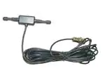
MHW Series dipole antennas feature a durable,
unobtrusive housing that sticks permanently with
integral adhesive to flat, non-conductive surfaces
such as windows, drywall, ceiling tiles, plastic,
etc. The antennas are well suited to low-power
devices, but are capable of operation at levels to
10 watts. The MHW is supplied with either 79"
[2m] or 180" [4.6m] of RG-174 cable and attaches
via a standard SMA or Part 15 compliant RP-SMA
connector. Custom cable lengths and connectors
are available for volume OEM customers.
)
0.38"
[9.7]
0.30"
[7.6]
(
2.19"
[55.5]
)
1.34"
[34]
0.22"
[5.5]
Features
•
•
•
•
•
•
•
•
5.70"
[145.0]
Compact & unobtrusive
Adhesive for flat surfaces
Excellent performance
Omni-directional pattern
Very low VSWR
Two flexible radiating elements
Rugged & damage-resistant
Standard SMA or Part 15 compliant
RP-SMA connector
0.61"
[15.5]
0.31"
[8.0]
Electrical Specifications
Center frequency:
Recommended Oper. Freq:
Wavelength:
VSWR:
Peak Gain:
Impedance:
Connection:
Cable:
433MHz
413–453MHz
½-wave
1.9 typical at center
1.2dBi
50-ohms
SMA or RP-SMA
79" or 180" RG-174 coax
Ordering Information
ANT-433-MHW-RPS-L (RP-SMA connector, 180" [4.6m] coax)
ANT-433-MHW-RPS-S (RP-SMA connector, 79" [2m] coax)
ANT-433-MHW-SMA-L (SMA connector, 180" [4.6m] coax)
ANT-433-MHW-SMA-S (SMA connector, 79" [2m] coax)
–1–
Revised 3/22/13
�VSWR Graph
VSWR
Reflected Power
1.18
3:1
25%
2:1
11%
1:1
368MHz
0%
498MHz
433MHz
What is VSWR?
The Voltage Standing Wave Ratio (VSWR) is a measurement of how well
an antenna is matched to a source impedance, typically 50-ohms. It is
calculated by measuring the voltage wave that is headed toward the load
versus the voltage wave that is reflected back from the load. A perfect
match will have a VSWR of 1:1. The higher the first number, the worse the
match, and the more inefficient the system. Since a perfect match cannot
ever be obtained, some benchmark for performance needs to be set. In
the case of antenna VSWR, this is usually 2:1. At this point, 88.9% of the
energy sent to the antenna by the transmitter is radiated into free space
and 11.1% is either reflected back into the source or lost as heat on
the structure of the antenna. In the other direction, 88.9% of the energy
recovered by the antenna is transferred into the receiver. As a side note,
since the “:1” is always implied, many data sheets will remove it and just
display the first number.
How to Read a VSWR Graph
VSWR is usually displayed graphically versus frequency. The lowest point
on the graph is the antenna’s operational center frequency. In most cases,
this will be different than the designed center frequency due to fabrication
tolerances. The VSWR at that point denotes how close to 50-ohms the
antenna gets. Linx specifies the recommended bandwidth as the range
where the typical antenna VSWR is less than 2:1.
–2–
Data Sheet ANT-433-MHW-xxx-x
by
�E / Vertical Gain
H / Horizontal Gain
Total Gain
Gain Plots
XZ-Plane Gain
YZ-Plane Gain
XY-Plane Gain
About Gain Plots
The true measure of the effectiveness of an antenna in any given application is determined by the gain and radiation pattern measurement. For
antennas gain is typically measured relative to a perfect (isotropic) radiator having the same source power as the antenna under test, the units of
gain in this case will be decibels isotropic (dBi). The radiation pattern is a
graphical representation of signal strength measured at fixed distance from
the antenna.
Gain when applied to antennas is a measure of how the antenna radiates
and focuses the energy received into free space. Much like a flashlight
focuses light from a bulb into a specific direction, antennas can focus RF
energy into specific directions. Gain in this sense refers to an increase in
energy in one direction over others.
It should also be understood that gain is not “free”, gain above 0dBi in one
direction means that there must be less gain in another direction. Pictorially this can be pictured as shown in the figures to the right. The orange
pattern represents the radiation pattern for a perfect dipole antenna,
which is shaped like a donut. The pattern for an omnidirectional antenna
with gain is shown in blue. The gain antenna is able to work with a device
located further from the center along the axis of the pattern, but not with
devices closer to the center when they are off the axis – the donut has
been squished.
Gain is also related to the overall physical size of the antenna, as well as
surrounding materials. As the geometry of the antenna is reduced below
the effective wavelength (considered an electrically small antenna) the gain
will decrease. As well, the relative distance between an electrically small
antenna and its associated ground will impact antenna gain.
159 Ort Lane, Merlin, OR, US 97532
Phone: +1 541 471 6256
Fax: +1 541 471 6251
www.linxtechnologies.com
–3–
Data Sheet ANT-433-MHW-xxx-x
by
�
很抱歉,暂时无法提供与“ANT-433-MHW-RPS-S”相匹配的价格&库存,您可以联系我们找货
免费人工找货