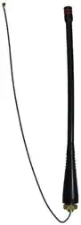
ANT-433-PW-QW-UFL

ANT-433-PW-QW-UFL

  • 厂商:

    LINXTECHNOLOGIES(灵思)

  • 封装:

    -

  • 描述:

    PW系列14波段鞭状天线,设计用于,具有出色的性能,结构坚固且成本效益高。天线通过产品上的6.35 mm孔固定,并通过8.5英寸RG-174同轴电缆或1.32 mm U.FL同轴电缆连接。

  • 详情介绍
  • 数据手册
  • 价格&库存
ANT-433-PW-QW-UFL 数据手册
ANT-433-PW-QW-xxx Data Sheet by Product Description 7.8 mm (0.31") Designed for permanent attachment, PW Series ¼-wave whips give outstanding performance in a rugged and cost-effective package. The antenna is attached by placing its base through a ¼" (6.35 mm) hole in the product and securing it with a nut or by threading it into a PEM-style insert. The antenna is fed through the base with 8.5" (216 mm) of coax cable. Straight-cut RG-174 allows the addition of any 50-ohm RF connector or allows the cable to be soldered directly to the PCB, saving the cost of the connector. It is also available with 1.32 mm coax cable terminated with a U.FL / MHF compatible connector. This saves the labor of adding a connector while using one that is small enough to fit through the antenna’s mounting hole. Custom lengths and terminations are available by special order. 13.0 mm (0.51") 6.0 mm (0.24") 173.0 mm (6.81") Straight Cut or U.FL I-PEX silhouette shown in shadow Features • • • • • • • Low cost Outstanding performance Omni-directional pattern Wide bandwidth Flexible main shaft Rugged & weatherized Integral 8.5" (216 mm) RG-174 coax cable or 1.32 mm coax (U.FL) • Use with plastic* or metal enclosures 52.0 mm (2.05") 4.5 mm (0.18") 1/4-28 UNF 216 mm (8.5") * Requires proximity ground plane 7/16" HEX 14.5 mm (0.57") Electrical Specifications Center Frequency: Bandwidth: Wavelength: VSWR: Peak Gain: Impedance: Connection: Cable: Oper. Temp. Range: 433MHz 400–470MHz ¼-wave ≤ 1.9 typical at center 3.3dBi 50-ohms Straight-cut or U.FL/MHF 8.5” (216 mm) RG-174 coax cable or 1.32 mm coax (U.FL) –40°C to +90°C End View Ordering Information ANT-433-PW-QW (with straight cut RG-174 coax) ANT-433-PW-QW-UFL (U.FL/MHF compatible connector) Electrical specifications and plots measured on 10.16 cm x 10.16 cm (4.00" x 4.00") reference ground plane –1– Revised 1/26/15 Counterpoise Quarter-wave or monopole antennas require an associated ground plane counterpoise for proper operation. The size and location of the ground plane relative to the antenna will affect the overall performance of the antenna in the final design. When used in conjunction with a ground plane smaller than that used to tune the antenna, the center frequency typically will shift higher in frequency and the bandwidth will decrease. The proximity of other circuit elements and packaging near the antenna will also affect the final performance. For further discussion and guidance on the importance of the ground plane counterpoise, please refer to Linx Application Note AN-00501: Understanding Antenna Specifications and Operation. VSWR Graph VSWR 3:1 Reflected Power 25% 1.095 2:1 1:1 333.92MHz 11% 0% 533.92MHz 433.92MHz What is VSWR? The Voltage Standing Wave Ratio (VSWR) is a measurement of how well an antenna is matched to a source impedance, typically 50-ohms. It is calculated by measuring the voltage wave that is headed toward the load versus the voltage wave that is reflected back from the load. A perfect match will have a VSWR of 1:1. The higher the first number, the worse the match, and the more inefficient the system. Since a perfect match cannot ever be obtained, some benchmark for performance needs to be set. In the case of antenna VSWR, this is usually 2:1. At this point, 88.9% of the energy sent to the antenna by the transmitter is radiated into free space and 11.1% is either reflected back into the source or lost as heat on the structure of the antenna. In the other direction, 88.9% of the energy recovered by the antenna is transferred into the receiver. As a side note, since the “:1” is always implied, many data sheets will remove it and just display the first number. How to Read a VSWR Graph VSWR is usually displayed graphically versus frequency. The lowest point on the graph is the antenna’s operational center frequency. In most cases, this will be different than the designed center frequency due to fabrication tolerances. The VSWR at that point denotes how close to 50-ohms the antenna gets. Linx specifies the recommended bandwidth as the range where the typical antenna VSWR is less than 2:1. –2– Data Sheet ANT-433-PW-QW-xxx by
ANT-433-PW-QW-UFL
物料型号:ANT-433-PW-QW-xxx

器件简介:PW系列四分之一波长天线,具有出色的性能和坚固耐用性,同时成本效益高。适用于永久性安装,通过在产品上打一个1/4英寸(6.35毫米)的孔,并将天线底座穿过并用螺母固定,或者将其螺纹插入PEM式嵌件。天线通过底座以8.5英寸(216毫米)的同轴电缆进行馈电。

引脚分配:文档中没有提供具体的引脚分配信息。

参数特性: - 中心频率:433MHz - 带宽:400-470MHz - 波长:四分之一波长 - VSWR:典型值≤1.9 - 增益:3.3dBi - 阻抗:50欧姆 - 连接:直切或U.FL/MHF - 电缆:8.5英寸(216毫米)RG-174同轴电缆或1.32毫米同轴电缆(U.FL) - 操作温度范围:-40°C至+90°C

功能详解:PW系列天线是全向天线,具有宽广的带宽和灵活的主体,适合塑料或金属外壳使用,需要接近地面平面。

应用信息:四分之一波长或单极天线需要与相应的地面平面进行配合,以确保天线正常工作。地面平面的大小和位置会影响天线的整体性能。

封装信息:文档中未提供封装信息
ANT-433-PW-QW-UFL 价格&库存

很抱歉,暂时无法提供与“ANT-433-PW-QW-UFL”相匹配的价格&库存,您可以联系我们找货

免费人工找货
ANT-433-PW-QW-UFL
  •  国内价格
  • 1+128.64213
  • 13+126.06992
  • 25+123.53935

库存:36