ANT-DB1-VDP-xxx
Data Sheet
by
Product Description
22.0 mm
(0.87")
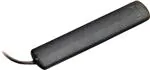
The VDP Series is a compact, center-fed antenna
that achieves efficient operation at any or all three
frequency bands. Its durable, unobtrusive housing
attaches permanently with integral adhesive to flat,
non-conductive surfaces such as windows, drywall,
ceiling tiles, plastic, etc. The antenna is supplied
with 9.8 feet (3m) of RG-174 cable that enters from
the bottom to facilitate vertical orientation. It can be
terminated in a TNC, standard SMA, or FCC Part
15 compliant RP-SMA connector.
4.52 mm
(0.18")
115.0 mm
(4.53")
Features
• Tri-band (824–960MHz, 1.71–1.99GHz and
2.40–2.48GHz)
• Center-fed from the bottom
• Surface-mount
• Low VSWR
• Excellent performance
• Omni-directional pattern
• Fully weatherized, durable & unobtrusive
• TNC, SMA or RP-SMA connector
Electrical Specifications
Recom. Freq. Range: Band 1: 824–960MHz
Band 2: 1.71–1.99GHz
Band 3: 2.40–2.48GHz
Wavelength:
½-wave
VSWR: Band 1: ≤1.5 typ. at center
Band 2: ≤1.9 typ. at center
Band 3: ≤1.9 typ. at center
Peak Gain:
Band 1: –1.8dBi
Band 2: –1.7dBi
Band 3: –1.3dBi
Impedance: 50-ohms
Connector:
TNC, SMA or RP-SMA
Cable:
9.8' (3 m) RG-174 coax
Oper. Temp. Range:
–40°C to +80°C
14.0 mm
(0.55")
TNC
connector
7.9 mm
(0.31")
SMA,
RP-SMA
connector
Ordering Information
ANT-DB1-VDP-TNC (with TNC connector)
ANT-DB1-VDP-SMA (with SMA connector)
ANT-DB1-VDP-RPS (with RP-SMA connector)
–1–
Revised 1/23/14
�VSWR Graph
VSWR
3:1
1.530
2.028
2.024 Reflected Power
25%
2:1
11%
1:1
0%
CENTER 910.000MHz
CENTER 1 825.000MHz
CENTER 2 450.000MHz
SPAN 200.000MHz
What is VSWR?
The Voltage Standing Wave Ratio (VSWR) is a measurement of how well
an antenna is matched to a source impedance, typically 50-ohms. It is
calculated by measuring the voltage wave that is headed toward the load
versus the voltage wave that is reflected back from the load. A perfect
match will have a VSWR of 1:1. The higher the first number, the worse the
match, and the more inefficient the system. Since a perfect match cannot
ever be obtained, some benchmark for performance needs to be set. In
the case of antenna VSWR, this is usually 2:1. At this point, 88.9% of the
energy sent to the antenna by the transmitter is radiated into free space
and 11.1% is either reflected back into the source or lost as heat on
the structure of the antenna. In the other direction, 88.9% of the energy
recovered by the antenna is transferred into the receiver. As a side note,
since the “:1” is always implied, many data sheets will remove it and just
display the first number.
How to Read a VSWR Graph
VSWR is usually displayed graphically versus frequency. The lowest point
on the graph is the antenna’s operational center frequency. In most cases,
this will be different than the designed center frequency due to fabrication
tolerances. The VSWR at that point denotes how close to 50-ohms the
antenna gets. Linx specifies the recommended bandwidth as the range
where the typical antenna VSWR is less than 2:1.
159 Ort Lane, Merlin, OR, US 97532
Phone: +1 541 471 6256
Fax: +1 541 471 6251
www.linxtechnologies.com
–2–
Data Sheet ANT-DB1-VDP-xxx
by
�
很抱歉,暂时无法提供与“ANT-DB1-VDP-RPS”相匹配的价格&库存,您可以联系我们找货
免费人工找货