SPECIFICATION
Part No.
:
PC240.09.0300K
Product Name
:
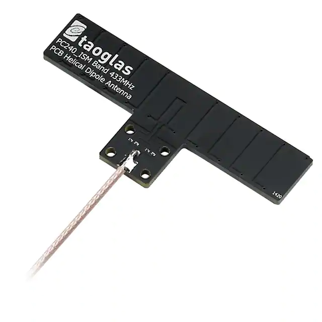
Embedded T-Bar 433MHz
Adhesive/Screw Mounted Helical Dipole
with 0.3M RG316 MMCX(M)RA
Features
:
Omni-Directional
96mm x 40mm x 3mm
Integrated LC tank Balun to prevent influence of
cable routing and cable length
-1dBi Peak Gain @ 433MHz
48% high efficiency
300mm RG316 Coaxial Cable
MMCX(M) Right Angle Connector
Low profile – only 3mm in thickness
RoHS Compliant
Photo:
SPE-15-8-011/A/WY
Page 1 of 15
�1. Introduction
The PC240.09.0300K is a 433MHz embedded omni-directional adhesive / screw
mounted, linear polarised, dipole antenna with high efficiency at only 96mm in
length.
The antenna was specifically designed for use in wireless alarm devices. It
operates in license-free ISM band, making the PC240.09.0300K a suitable
antenna in systems such as home security & alarm, home automation, metering,
remote control, industrial control, and other 433MHz applications.
Most low frequency antennas detune inside enclosures when the cable is moved
to new orientations. In order to mitigate the influence of cable routing direction
while installing, the PC240.09.0300K uses a LC tank balun circuit. The LC tank
balun circuit stabilizes the electrical characteristics when cable length changes.
Please refer to Application Note (Section 7) for more details.
The PC240.09.0300K is designed as a helical dipole structure, which can
significantly shorten the length while maintaining high efficiency. Users can
easily attach the antenna on their device housing via the 3M adhesive, without
worrying about their housing detuning the antenna as it has been tuned on a
2mm thick ABS board, which is typical enclosure thickness and material for
electronic devices. It also has four thru holes that users can fix the antenna with
screws.
With the balun circuit and helical dipole design, the PC240.09.0300K is truly a
miniature 433 MHz PCB antenna, which can provide worry-free cable routing
during installation.
SPE-15-8-011/A/WY
Page 2 of 15
�2. Specification
ELECTRICAL
Application Band
ISM
Operation Frequency (MHz)
433
Cable length (M)
0.3
On 2mm thickness ABS
Average Gain (dB)
-3.14
Efficiency (%)
48.82
Peak Gain
-0.97
Base
VSWR
< 2:1
Return Loss (dB)
< -10
Polarization
Linear
Impedance
50 Ohms
MECHANICAL
Dimension (mm)
Height = 3 mm, Length = 96 mm, Width = 40 mm
Cable length
300mm RG316 – Fully Customizable
Connector
MMCX(M) RA – Fully Customizable
Material
Composite
Weight (g)
18
ENVIRONMENTAL RATINGS
Temperature Range
-40°C to +85°C
Thermal Shock
100 cycles -40°C to +85°C
Humidity
Non-condensing 65°C 95% RH
Cable Pulling Force
18.2kgF
SPE-15-8-011/A/WY
Page 3 of 15
�3. Antenna Characteristics
3.1 Testing Setup
PC240 antenna was tested with R&S ZNB-8 network analyzer.
On 2mm thick ABS base
3.2 Return Loss
433MHz
SPE-15-8-011/A/WY
Page 4 of 15
�3.3 Average Gain
3.4 Efficiency
SPE-15-8-011/A/WY
Page 5 of 15
�3.5 Peak Gain
4. Antenna Radiation Patterns
4.1 Antenna Setup
The antenna radiation pattern measurement setup is shown below.
Y
Z
X
SPE-15-8-011/A/WY
Page 6 of 15
�4.2 Antenna Radiation Patterns
2D Patterns
YZ Plane
XY Plane
SPE-15-8-011/A/WY
Page 7 of 15
�XZ Plane
3D Patterns
SPE-15-8-011/A/WY
Page 8 of 15
�5. Drawing
SPE-15-8-011/A/WY
Page 9 of 15
�6. Packaging (unit: mm)
SPE-15-8-011/A/WY
Page 10 of 15
�SPE-15-8-011/A/WY
Page 11 of 15
�7. Application Note
7.1 PC240 antenna cable routing effects
Position 1
Position 2
Position 3
Cable Routing
SPE-15-8-011/A/WY
Page 12 of 15
�7.2 PC240 with long cable effects
PC240 with extra 150cm cable
Through these two experiments, the LC tank Balun has isolated cable effects to
antenna resonance.
SPE-15-8-011/A/WY
Page 13 of 15
�8. Installation Recommendations
PC240 antenna is a resonant arm meandered non-standard dipole novel
antenna design. However, it still keeps the same radiation characteristics
as standard dipole antennas. It has an omni-directional radiation pattern in
the H-Plane(2D YZ Plane in the spec). The installation recommendation of
this antenna is mounting the antenna internally on the side walls of the
device, with one of the arms of the T pointing downwards
For either of the antenna installations shown above, the antenna will
exhibit the radiation pattern as shown below.
SPE-15-8-011/A/WY
Page 14 of 15
�Orange means much higher antenna gains, Green means the weakest
antenna gains. So the correct application of this antenna is to let the
antenna edges as below face the sky and Earth. Then the antenna can have
omni-directional radiation patterns that are horizontal to the Earth.
SPE-15-8-011/A/WY
Page 15 of 15
�
很抱歉,暂时无法提供与“PC240.09.0300K”相匹配的价格&库存,您可以联系我们找货
免费人工找货- 国内价格 香港价格
- 1+167.993401+21.79701