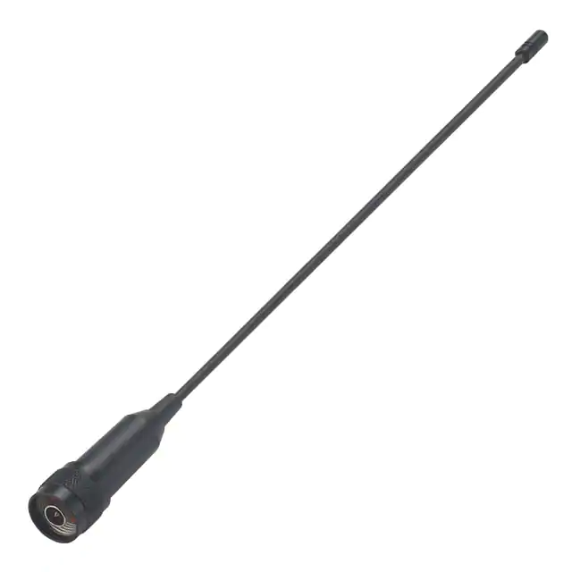
Meteor
Part No:
FW.24.NTY.M
Description:
Meteor-2.4GHz Flexible Whip Monopole Antenna N Type(M) Straight
Features:
External 2.4GHz Monopole Antenna
Designed for Outdoor Use
Omni-directional
Over 70% Efficiency*
Over 4dBi peak gain*
Robust Inner Steel Core
Antenna height 316mm
N Type(M) Straight Connector
IP65 dust and water-resistant
*Tested on 30cm*30cm Ground Plane
RoHS Compliant
SPE-15-8-033/C/AW
�1.
Introduction
3
2.
Specifications
5
3.
Antenna Characteristics
6
4.
Radiation Patterns
9
5.
Mechanical Drawing
12
6.
Packaging
13
Changelog
14
Taoglas makes no warranties based on the accuracy or completeness of the contents of this document and reserves the right to
make changes to specifications and product descriptions at any time without notice. Taoglas reserves all rights to this document and
the information contained herein. Reproduction, use or disclosure to third parties without express permission is strictly prohibited.
SPE-15-8-033/C/AW
www.taoglas.com
2
�1.
Introduction
1.
Introduction
1.
Introduction
1.
Introduction
1.
The FW.24 is a flexible 2.4GHz omni-directional whip antenna with an N type (M) connector for outdoor use.
It features excellent efficiency (>75%) and high peak gain (>4 dBi) between 2400-2500MHz on a 30x30 cm
ground plane.
1.
The antenna was specifically developed for applications in outdoor monitoring systems, such as weather
monitoring, motion/vibration sensors, and pollutants monitoring.
1.
1.
Introduction
Introduction
The FW.24 works in the 2.4GHz Wi-Fi/Bluetooth/ISM band. It has excellent omni-directional radiation
properties providing a wide coverage area in the azimuth. Its high efficiency means that it allows your radio
to consume less power than with a lower efficiency antenna when transferring data, while also achieving
better sensitivity of reception. The antenna performs at its best while attached to a ground plane with
dimensions of at least 30x30 cm, though it can be used even without ground-plane.
Introduction
Introduction
The whip is made of a flexible inner steel core covered by PE so it is extremely resistant to abrasion and
springs back to its original shape if bent. The rugged design and its housing’s IP65 rating ensure it can
withstand bad weather, environmental stress and physical shock in the field.
Many module manufacturers specify peak gain limits for any antennas that are to be connected to that
module. Those peak gain limits are based on free-space conditions. In practice, the peak gain of an antenna
tested in free-space can degrade by at least 1 or 2dBi when put inside a device. So ideally you should go for
a slightly higher peak gain antenna than mentioned on the module specification to compensate for this effect,
giving you better performance.
Upon testing of any of our antennas with your device and a selection of appropriate layout, integration
technique, or cable, Taoglas can make sure any of our antennas’ peak gain will be below the peak gain limits.
Taoglas can then issue a specification and/or report for the selected antenna in your device that will clearly
show it complying with the peak gain limits, so you can be assured you are meeting regulatory requirements
for that module.
SPE-15-8-033/C/AW
www.taoglas.com
3
�For example, a module manufacturer may state that the antenna must have less than 2dBi peak gain, but
you don’t need to select an embedded antenna that has a peak gain of less than 2dBi in free-space. This will
give you a less optimized solution. It is better to go for a slightly higher free-space peak gain of 3dBi or more
if available. Once that antenna gets integrated into your device, performance will degrade below this 2dBi
peak gain due to the effects of GND plane, surrounding components, and device housing. If you want to be
absolutely sure, contact Taoglas and we will test. Choosing a Taoglas antenna with a higher peak gain than
what is specified by the module manufacturer and enlisting our help will ensure you are getting the best
performance possible without exceeding the peak gain limits.
Other connector options are available or custom versions can be made subject to NRE and MOQ. Contact
your regional Taoglas office for details.
SPE-15-8-033/C/AW
www.taoglas.com
4
�2.
Specifications
3.
Antenna Characteristics2.
3.
4.
4.
2400~2500MHz
In free space
On 30x30cm ground
64. %
79.3%
4.26dBi
4.48dBi
Return loss
< -6dB
< -10dB
VSWR
≤ 3:1
≤ 2:1
Efficiency
Antenna
Characteristics
Peak Gain
Antenna
Radiation Patterns3.Antenna
Impedance
Polarization
3.
Specifications
Frequency
Characteristics2.
Radiation Pattern
3.
2.4GHz
50Ω
Linear
Specifications
Omni-Directional
Input Power
2W
Total Power
10 W
Antenna Characteristics2.
Specifications
Mechanical
Dimensions
Height 316 ± 9 mm
Base Diameter
20 ± 0.5 mm
Whip Diameter
Antenna
Characteristics
6.2 ± 0.6 mm
Casing
ABS & PE
Connector
N type Male Straight
Weight
46.6 g
Antenna
Radiation Patterns3.AntennaIP65 (housing only)
Dust and Water Resistance
Characteristics
Environmental
Temperature Range
-40°C to 85°C
Humidity
Non-condensing 65°C 95% RH
4.
Antenna Radiation Patterns
4.
Antenna Radiation Patterns3.Antenna
Characteristics
4.
Antenna Radiation Patterns3.Antenna
Characteristics2.
SPE-15-8-033/C/AW
Specifications
www.taoglas.com
5
�3.
Antenna Characteristics
4.
Antenna Radiation Patterns3.Antenna
3.1
Return Loss
Characteristics
4.
Antenna Radiation Patterns
4.
Antenna Radiation Patterns3.Antenna
Characteristics
4.
Antenna Radiation Patterns3.Antenna
Characteristics
4.
Antenna Radiation Patterns
4.
Antenna Radiation Patterns
4.
Antenna Radiation Patterns
4.
Antenna Radiation Patterns3.Antenna
Characteristics
4.
Antenna Radiation Patterns3.Antenna
SPE-15-8-033/C/AW
www.taoglas.com
6
�3.2
Efficiency
SPE-15-8-033/C/AW
www.taoglas.com
7
�3.3
Peak Gain
SPE-15-8-033/C/AW
www.taoglas.com
8
�4.
Radiation Patterns
4.
4.
4.
4.
4.1
Antenna Radiation Patterns
Test Setup
Antenna Radiation Patterns
Antenna Radiation Patterns
Y
X
4.
Antenna Radiation Patterns
4.
Antenna Radiation PatternsFree space
4.
Antenna Radiation Patterns
4.
Antenna Radiation Patterns
Z
On 30x30 cm ground plane
SPE-15-8-033/C/AW
www.taoglas.com
9
�4.2
3D and 2D Radiation Patterns
3-D Radiation Pattern in free space @2450MHz
XY Plane
XZ Plane
YZ Plane
X
Z
Z
Y
SPE-15-8-033/C/AW
X
Y
www.taoglas.com
10
�3-D Radiation Pattern on 30cm*30cm Ground Plane @2450MHz
XY Plane
XZ Plane
YZ Plane
X
Z
Z
Y
SPE-15-8-033/C/AW
X
Y
www.taoglas.com
11
�5.
Mechanical Drawing (Units: mm)
6.
Packaging5.
6.
Packaging
7.
Application Note6. Packaging5.
Mechanical Drawing
Mechanical
Drawing
6.
Packaging5.
Mechanical Drawing
6.
Packaging
7.
Application Note6. Packaging
7.
Application Note
7.
Application Note6. Packaging
7.
Application Note6. Packaging5.
Mechanical
Drawing
8.
6.
Packaging
Packaging5.
SPE-15-8-033/C/AW
Mechanical Drawing
www.taoglas.com
12
�6.
Packaging
6. 1pcs FW.24.NTY.M
Packaging5.
per PE Bag
Mechanical Drawing
Bag Dimensions - 380*50mm
Weight - 50g
6.
Packaging
7. 50 PEApplication
Note6. Packaging5.
Bags per Large PE Bag
Mechanical
Bag Dimensions - 460*380mm
Weight - 2.5Kg
Drawing
6.
Packaging5.
6.
Packaging
7.
Mechanical Drawing
4 Large PE Bags per Carton
Carton Dimensions - 400*300*250mm
Weight - 10.5Kg
Application Note6. Packaging
7.
Application Note
7.
Application Note6. Packaging
7.
Pallet Dimensions:
1100*1200*1500mm
60 Cartons Per Pallet
12 Cartons Per Layer
5 Layers
Application Note6. Packaging5.
Mechanical
Drawing
6.
Packaging5.
SPE-15-8-033/C/AW
Mechanical Drawing
www.taoglas.com
13
�Changelog for the datasheet
SPE-15-8-033 - FW.24.NTY.M
Revision: C (Current Version)
Date:
Changes:
Changes Made by:
2019-08-12
New design
David Connolly
Previous Revisions
Revision: B
Date:
Changes:
Changes Made by:
2015-08-24
Added note on Gain
Aine Doyle
Revision: A (Original First Release)
Date:
Notes:
2015-06-11
Author:
Wayne Yang
SPE-15-8-033/C/AW
www.taoglas.com
14
�www.taoglas.com
SPE-15-8-033/C/AW
© Taoglas
www.taoglas.com
15
�
很抱歉,暂时无法提供与“FW.24.NTY.M”相匹配的价格&库存,您可以联系我们找货
免费人工找货- 国内价格 香港价格
- 1+196.465881+25.41811