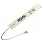
Avia 3G FPC Antenna
Part No. SRFC025
1.
flexiiANT ®
Product Specification
Features
2.
Antenna for 3G applications including MIMO systems.
GSM850, GSM900, DCS1800, PCS1900, WCDMA2100
1.13mm diameter RF cable with IPEX MHF connector
Self-adhesive mounted
Quick and simple integration minimizes design cycle
Available in 3 standard cable lengths
Description
Avia is intended for use with 3G applications. This product specification shows the
performance of the antenna to cover a typical penta-band reception:
GSM850/900/1800/1900 and WCDMA.
3.
Applications
Smart meters
Femto / Pico base stations
Tracker devices
Remote monitoring
Machine to Machine
POS (Point of Sale) terminals
Antennas for Wireless M2M Applications
Product Specification PS SRFC025-1.0
Page 1
�Avia
Part No. SRFC025
4.
Part Number
Avia: SRFC025
5.
General Data
Product name
Avia GSM antenna
Part Number
SRFC025
Frequency
824-960MHz; 1710-2170MHz
Polarization
Linear
Operating temperature
-40°C to 85°C
Impedance with matching
50 Ω
Weight
< 0.5 g
Antenna type
FPC Self-adhesive 3M 468P
Dimensions (Antenna)
71.0 x 12.5 x 0.15 (mm)
Connection
IPEX
6.
RF Characteristics
824 – 960 MHz
1710 – 1990 MHz
2110 – 2170 MHz
Peak gain
4.07dBi
5.44dBi
3.9dBi
Average gain
-3.31dBi
-1.1dBi
-1.74dBi
Average efficiency
>45%
>70%
>65%
Maximum return loss
-6.6dB
-8.7dB
-17dB
Maximum VSWR
2.80:1
2.20:1
1.30:1
All data measured in a loaded condition
adhered to a plastic carrier free space.
Antennas for Wireless M2M Applications
Product Specification PS SRFC025-1.0
Page 2
�Avia
Part No. SRFC025
7.
RF Performance
7.1 Return Loss
5
[dB]
Atyune
0
-5 1
3
-10
2
-15
5
4
-20
6
-25
-30
[MHz]
-35
800
900
1000
1100
MARKERS: MHz
dB
RD8025-MP.S1P - S11
1200
MHz
1: 824 -6.60
2: 960 -14.39
1300
dB
3: 1710 -8.73
4: 1990 -19.67
1400
1500
MHz
1600
1700
1800
1900
2000
2100
2200
dB
5: 2110 -17.77
6: 2170 -22.02
7.2 VSWR
10
[]
Atyune
9
8
7
6
5
4
3 1
3
2
2
1
800
4
5
6
[MHz]
900
1000
1100
MARKERS: MHz
RD8025-MP.S1P - S11
1: 824
2: 960
2.76
1.47
1200
1300
MHz
3: 1710
4: 1990
1400
1500
1600
1700
1800
1900
2000
2100
2200
MHz
2.16
1.23
5: 2110
6: 2170
1.30
1.17
Antennas for Wireless M2M Applications
Product Specification PS SRFC025-1.0
Page 3
�Avia
Part No. SRFC025
7.3 Antenna patterns
7.3.1
824 MHz – 960 MHz
3D pattern at 890 MHz
Drag to rotate pattern and PCB by using Adobe Reader
(Click to Activate)
Antennas for Wireless M2M Applications
Product Specification PS SRFC025-1.0
Page 4
�Avia
Part No. SRFC025
7.3.2
1710 MHz – 2170 MHz
3D pattern at 1950 MHz
Drag to rotate pattern and PCB by using Adobe Reader
(Click to Activate)
Antennas for Wireless M2M Applications
Product Specification PS SRFC025-1.0
Page 5
�Avia
Part No. SRFC025
8. Antenna Dimensions
8.1 Dimensions FPC section
L
W
T
Length
Width
Thickness
71.0 ±0.2 (mm)
12.5 ±0.2 (mm)
0.15 (mm) nominal
All dimensions in mm
8.2 Dimensions assembled
SRFC025-100
SRFC025-150
SRFC025-200
L
L
L
160 ±2.0 (mm)
210 ±2.0 (mm)
260 ±2.0 (mm)
Antennas for Wireless M2M Applications
Product Specification PS SRFC025-1.0
Page 6
�Avia
Part No. SRFC025
8.3 IPEX Connector
I-PEX
Front
Material
Copper Alloy
Plating
Ag
Side
Back
5.0
3.0
All dimensions in mm
8.4 Assembly
I-PEX Connector
1.13mm ø Cable
FPC
Antennas for Wireless M2M Applications
Product Specification PS SRFC025-1.0
Page 7
�Avia
Part No. SRFC025
9. Electrical Interface
9.1 Host Interface
The host PCB requires the mating connector which is IPEX MHF (UFL) receptacle.
The location should be close to the chip/modules pin for the RF. Any feed from this
receptacle should be maintained at 50Ω impedance.
9.2 Transmission Line
All transmission lines should be designed to have a characteristic impedance of 50Ω.
• The length of the transmission lines should be kept to a minimum
• Any other parts of the RF system like transceivers, power amplifiers, etc, should
also be designed to have an impedance of 50 Ω
Once the material for the PCB has been chosen (PCB thickness and dielectric
constant), a coplanar transmission line can easily be designed using any of the
commercial software packages for transmission line design. For the chosen PCB
thickness, copper thickness and substrate dielectric constant, the program will
calculate the appropriate transmission line width and gaps on either side of the feed.
A DC blocking capacitor should be placed in line to protect the RF front end.
10. Mechanical Fixing
The antenna uses 3M 468MP adhesive on the reverse side of the FPC. The antenna
has an easy access split line to peel off to reveal the adhesive side. It is designed for
a one time fix to a clean smooth surface.
FPC back side
Split line for
easy peel
Antennas for Wireless M2M Applications
Product Specification PS SRFC025-1.0
Page 8
�Avia
Part No. SRFC025
10.0 Antenna Integration Guide
10.1 Placement
For placing the FPC antenna within a device, the host PCB size is not a factor like
with PCB mounted antennas. However placement still needs to follow some basic
rules, as any antenna is sensitive to its environment.
Using six spatial directions shown below as a guide. The antenna FPC section
should try to maintain a minimum of three directions free from obstructions to be able
to operate effectively. The other directions will have obstacles in their paths, these
directions still require a minimum clearance. These minimum clearances are further
defined in this section. The plastic case is not included in this, only metal
objects/components that will obstruct or come in close proximity to the antenna.
Six spatial directions relative to FPC
Antennas for Wireless M2M Applications
Product Specification PS SRFC025-1.0
Page 9
�Avia
Part No. SRFC025
10.2 Orientation of FPC
The orientation of the FPC with respect to the host PCB should be defined
depending on the unit. The proximity of the GND will have an influence on the
antenna so the PCB location relative to the antenna should be considered.
The FPC will normally be placed in one of the three following options for orientation.
In each option a distance (d) is the critical dimension to consider. Below shows the
minimum value of (d) for each. Other obstructions may increase this dimension.
1) Vertical mounted
FPC
Cable +Connector
d ≥ 2mm
PCB
1) Co-planar to PCB
d ≥ 15mm
2) Planar to PCB (Same plane)
d ≥ 2mm
10.3 Host PCB size
The host PCB size has a large effect on the performance. It is recommended for the
host PCB to be >1600mm². Any PCB which is smaller is advised to use Antenova
SRFC011 as a suitable cellular FPC.
Antennas for Wireless M2M Applications
Product Specification PS SRFC025-1.0
Page 10
�Avia
Part No. SRFC025
10.4 Device Integration example
An example of integration within a Telematics device. The FPC is shown adhered to
the inside of the device’s plastic housing. The cable routing is along the edge of the
PCB so as not to interfere with any other component. The length of the cable is
sufficient to allow ease of assembly when produced (SRFC025-100).
The FPC is kept at maximised distance away from the PCB.
Antenna fitted in the corner
location to enhance
performance.
Placement on the plastic case is
furthest away from the PCBs.
Antennas for Wireless M2M Applications
Product Specification PS SRFC025-1.0
Page 11
�Avia
Part No. SRFC025
11. Hazardous Material Regulation Conformance
The antenna has been tested to conform to RoHS requirements. A certificate of
conformance is available from Antenova M2M’s website.
12. Packaging
The antennas are stored in individual plastic (PE) bags. Then stored within a second
bag of 10pcs.
Single antenna per bag
10 units per second bag (Labelled)
12.1 Optimal Storage Conditions
Temperature
-10ºC to 40ºC
Humidity
Less than 75% RH
Shelf life
18 Months
Storage place
Away from corrosive gas and direct sunlight
Antennas should be stored in unopened sealed
manufacturer’s plastic packaging.
Packaging
Antennas for Wireless M2M Applications
Product Specification PS SRFC025-1.0
Page 12
�Avia
Part No. SRFC025
12.2 Label Information
Antenova Limited
Antenova Asia Ltd
4F, No 324, Sec 1, Nei-Hu Road
Nei-Hu District, Taipei 11493, Taiwan, ROC
60.00mm
info@antenova-m2m.com / www.antenova-m2m.com
Description: Avia
Part number: SRFC025
Quantity: 10
Date Code: YYWW
Manufacturer’s code number:
flexiiANT
®
90.00m
m
Antennas for Wireless M2M Applications
Product Specification PS SRFC025-1.0
Page 13
�Avia
Part No. SRFC025
www.antenova-m2m.com
Corporate Headquarters
North America Headquarters
Asia Headquarters
Antenova Limited
nd
2 Floor Titan Court
3 Bishop Square
Hatfield
AL10 9NA
UK
Antenova Limited
100 Brush Creek Road, Suite 103
Santa Rosa
California 95404
USA
Antenova Asia Limited
4F, No. 324, Sec. 1, Nei-Hu Road
Nei-Hu District
Taipei 11493
Taiwan, ROC
Tel: +1 707 890 5202
Email: sales@antenova-m2m.com
Tel: +886 (0) 2 8797 8630
Fax: +886 (0) 2 8797 6890
Email: sales@antenova-m2m.com
Tel: +44 1223 810600
Email: sales@antenova-m2m.com
Copyright® Antenova Ltd. All Rights Reserved. Antenova ®, Antenova M2M ®, gigaNOVA ® and the Antenova
product family names and the Antenova and Antenova M2M logos are trademarks and/or registered trademarks
of Antenova Ltd. Any other names and/or trademarks belong to their respective companies.
The materials provided herein are believed to be reliable and correct at the time of printing. Antenova does not
warrant the accuracy or completeness of the information, text, graphics or other items contained within this
information. Antenova further assumes no responsibility for the use of this information, and all such information
shall be entirely at the user’s risk.
Antennas for Wireless M2M Applications
Product Specification PS SRFC025-1.0
Release date March 2016
Page 14
�
很抱歉,暂时无法提供与“SRFC025-200”相匹配的价格&库存,您可以联系我们找货
免费人工找货- 国内价格 香港价格
- 1+36.801391+4.76125
- 10+27.8123810+3.59828
- 25+25.5650225+3.30752
- 100+23.09896100+2.98847
- 250+21.92258250+2.83627
- 500+21.21364500+2.74455
- 1000+20.630211000+2.66907
- 3000+19.909503000+2.57583