Datasheet
ANT-418-WRT-ccc
418 MHz External Panel-Mount Antenna
The ANT-418-WRT is a low-profile, panel-mount
dipole antenna designed for 418 MHz applications.
The ANT-418-WRT antenna’s compact size allows
it to be mounted in applications requiring a low
profile and external antenna performance.
The ANT-418-WRT antenna is designed with an
integrated counterpoise that eliminates the need
for additional ground plane in the product, making
it ideal for applications with non-conductive or RF
transparent enclosures.
Connector options for the ANT-418-WRT antenna
are: SMA plug (male pin), RP-SMA plug (female
socket) or MHF1/U.FL-type plug (female socket).
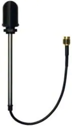
ANT-418-WRT-SMA Shown
Features
Applications
• Performance at 410 MHz to 427 MHz
― VSWR: ≤ 2.5
― Peak Gain: -0.5 dBi
― Efficiency: 31%
• Low-profile
― Height: 27.0 mm (1.10 in)
― Diameter: 19.0 mm (0.75 in)
• Mounts permanently with pressure sensitive
adhesive ring and provided nut
• Remote control, sensing and monitoring
― Security systems
― Industrial machinery
― Automated equipment
― AMR (automated meter reading)
• Internet of Things (IoT) devices
• Smart Home networking
Ordering Information
Part Number
ANT-418-WRT-RPS
ANT-418-WRT-SMA
ANT-418-WRT-UFL
Description
Antenna, 216 mm (8.50 in) of RG-174 coaxial cable, RP-SMA plug (female socket)
Antenna, 216 mm (8.50 in) of RG-174 coaxial cable, SMA plug (male pin)
Antenna, 216 mm (8.50 in) of 1.32 mm coaxial cable, MHF1/U.FL-type plug (female socket)
Available from Linx Technologies and select distributors and representatives.
�WRT Series
ANT-418-WRT-ccc
Datasheet
Table 1. Electrical Specifications
ANT-418-WRT
418 MHz
410 MHz to 427 MHz
Frequency Range
VSWR (max)
2.5
Peak Gain (dBi)
-0.5
Average Gain (dBi)
-5.3
31
Efficiency (%)
Polarization
Linear
Radiation
Impedance
50 Ω
Max Power
Wavelength
1/2-wave
Omnidirectional
5W
Dipole
Electrical Type
Electrical specifications and plots measured with a 102 mm x 102 mm (4.0 in x 4.0 in) reference ground plane.
Table 2. Mechanical Specifications
Connection
Coaxial Cable, minimum
inside bend radius
Weight
ANT-418-WRT-UFL
MHF1/U.FL-type plug
1.32 mm: 6.0 mm (0.24 in)
216 mm = 9.4 g (0.33 oz)
ANT-418-WRT-RPS
RP-SMA plug
1.32 mm: 6.0 mm (0.24 in)
216 mm = 14.4 g (0.51 oz)
ANT-418-WRT-SMA
SMA plug
0.81 mm: 4.0 mm (0.16 in)
216 mm = 14.4 g (0.51 oz)
Part Number
-40 °C to +90 °C
Operating Temp. Range
Height: 10.0 mm (0.40 in), Diameter: 19.0 mm (0.75 in)
Dimensions
Packaging Information
The ANT-418-WRT antenna is placed in a clear plastic sleeve and sealed in clear plastic bags in quantities of
50 pcs. Bags are packaged in cartons of 250 (5 bags). Distribution channels may offer alternative packaging
options.
Product Dimensions
Figure 1 provides dimensions for the ANT-418-WRT series antenna.
Ø19.0 mm
(0.75 in)
Adhesive Ring
8-sided plastic nut and mounting shaft
M11 x 1.0 mm
Ø5.3 mm (0.21 in)
Counterpoise
-SMA
-RPS
-UFL
85.0 mm (3.35 in)
8.0 mm
(0.32 in)
See Ordering Information for
cable length and termination options
Figure 1. ANT-418-WRT Antenna Dimensions
-MHF4
Recommended Mounting
2
Ø10.8 mm
(0.43 in)
27.0 mm
(1.10 in)
�WRT Series
ANT-418-WRT-ccc
Datasheet
Recommended Mounting
8-s
The recommended enclosure mounting
dimensions areMounting
shown in Figure 2. The ANT-418-WRT series
Recommended
antenna is supplied with an integrated closed-cell pressure sensitive adhesive ring which helps seal
-SMA, -RPS
enclosures against external elements. The adhesive ring has a protective plastic backing that
must be
removed prior to installation. A pull tab has been provided for easy removal of the protective backing. The
antenna can be permanently mounted using the provided nut which should be tightened-MHF1/-U.FL
to 4.0 kgf/cm (5 in/
lbs) max. The recommended maximum enclosure wall thickness is 4.70 mm (0.188 in).
Ø5.
C
-MHF4
Ø10.8 mm
(0.43 in)
See O
cable leng
Figure 2. ANT-418-WRT Series Antenna Recommended Enclosure Mounting Dimensions
Antenna Orientation
The ANT-418-WRT antenna is characterized in two antenna orientations as shown in Figure 3. The antenna
in free space characterizes use of an antenna attached to an enclosure-mounted connector which is
connected by cable to a printed circuit board. Although the antenna is a dipole not requiring a ground
plane for function, characterization with an adjacent ground plane (102 mm x 102 mm) provides insight
into antenna performance when attached directly to a printed circuit board mounted connector. The two
orientations represent the most common end-product use cases.
Free Space
Center of Ground Plane
Figure 3. ANT-418-WRT Test Orientations
3
�WRT Series
ANT-418-WRT-ccc
Datasheet
Free Space, No Ground Plane
The charts on the following pages represent data taken with the antenna oriented in free space without a
ground plane, as shown in Figure 4.
Figure 4. ANT-418-WRT in Free Space, No Ground Plane
VSWR
5
427
410
Figure 5 provides the voltage standing wave ratio (VSWR) across the antenna bandwidth. VSWR describes
the power reflected from the antenna back to the radio. A lower VSWR value indicates better antenna
performance at a given frequency. Reflected power is also shown on the right-side vertical axis as a gauge
of the percentage of transmitter power reflected back from the antenna.
VSWR
4
30
3
20
2
1
10
400
405
410
415
420
Frequency (MHz)
425
Figure 5. ANT-418-WRT VSWR, Free Space
4
430
435
0
Reflected Power (%)
40
�WRT Series
ANT-418-WRT-ccc
Datasheet
Return Loss
0
427
410
Return loss (Figure 6), represents the loss in power at the antenna due to reflected signals. Like VSWR, a
lower return loss value indicates better antenna performance at a given frequency.
-2
Return Loss (dB)
-4
-6
-8
-10
-12
-14
-16
-18
-20
400
405
410
415
420
Frequency (MHz)
425
430
435
Figure 6. ANT-418-WRT Return Loss, Free Space
Peak Gain
5
427
410
The peak gain across the antenna bandwidth is shown in Figure 7. Peak gain represents the maximum
antenna input power concentration across 3-dimensional space, and therefore peak performance at a given
frequency, but does not consider any directionality in the gain pattern.
Peak Gain (dBi)
0
-5
-10
-15
-20
400
405
410
415
420
Frequency (MHz)
425
430
435
Figure 7. ANT-418-WRT Peak Gain, Free Space
5
�WRT Series
ANT-418-WRT-ccc
Datasheet
Average Gain
5
427
410
Average gain (Figure 8), is the average of all antenna gain in 3-dimensional space at each frequency,
providing an indication of overall performance without expressing antenna directionality.
Average Gain (dBi)
0
-5
-10
-15
-20
400
405
410
415
420
Frequency (MHz)
425
430
435
Figure 8. ANT-418-WRT Antenna Average Gain, Free Space
Radiation Efficiency
100
427
410
Radiation efficiency (Figure 9), shows the ratio of power delivered to the antenna relative to the power
radiated at the antenna, expressed as a percentage, where a higher percentage indicates better
performance at a given frequency.
90
80
Efficiency (%)
70
60
50
40
30
20
10
0
400
405
410
415
420
Frequency (MHz)
425
Figure 9. ANT-418-WRT Antenna Radiation Efficiency, Free Space
6
430
435
�WRT Series
ANT-418-WRT-ccc
Datasheet
Radiation Patterns
Radiation patterns provide information about the directionality and 3-dimensional gain performance of the
antenna by plotting gain at specific frequencies in three orthogonal planes. Antenna radiation patterns are
shown in Figure 10 using polar plots covering 360 degrees. The antenna graphic at the top of the page
provides reference to the plane of the column of plots below it. Note: when viewed with typical PDF viewing
software, zooming into radiation patterns is possible to reveal fine detail.
Radiation Patterns - Free Space
XZ-Plane Gain
YZ-Plane Gain
XY-Plane Gain
410 MHz to 427 MHz (418 MHz)
34
35
33
32
31
30
29
28
36 5
0
-5
-10
-15
-20
-25
-30
-35
-40
-45
-50
1
2
3
4
34
5
33
6
32
7
31
8
27
26
30
9
29
10
28
11
27
12
25
13
24
14
23
15
22
21
20
19
18
XZ-Plane Gain
17
16
35
36 5
0
-5
-10
-15
-20
-25
-30
-35
-40
-45
-50
1
2
3
4
34
5
33
6
32
7
31
8
26
30
9
29
10
28
11
27
12
25
13
24
14
23
15
22
21
20
19
18
17
16
35
36 5
0
-5
-10
-15
-20
-25
-30
-35
-40
-45
-50
1
2
3
4
5
6
7
8
9
10
11
26
12
25
13
24
14
23
15
22
21
YZ-Plane Gain
20
19
18
17
16
410 MHz
418.5 MHz
427 MHz
XY-Plane Gain
Figure 10. ANT-418-WRT Radiation Patterns, Free Space
7
�WRT Series
ANT-418-WRT-ccc
Datasheet
Center of Ground Plane
The charts on the following pages represent data taken with the antenna oriented at the center of the
ground plane, as shown in Figure 11.
Figure 11. ANT-418-WRT at Center of Ground Plane
VSWR
5
427
410
Figure 12 provides the voltage standing wave ratio (VSWR) across the antenna bandwidth. VSWR describes
the power reflected from the antenna back to the radio. A lower VSWR value indicates better antenna
performance at a given frequency. Reflected power is also shown on the right-side vertical axis as a gauge
of the percentage of transmitter power reflected back from the antenna.
VSWR
4
30
3
20
2
1
10
400
405
410
415
420
Frequency (MHz)
425
430
Figure 12. ANT-418-WRT VSWR, at Center of Ground Plane
8
435
0
Reflected Power (%)
40
�WRT Series
ANT-418-WRT-ccc
Datasheet
Return Loss
0
427
410
Return loss (Figure 13), represents the loss in power at the antenna due to reflected signals. Like VSWR, a
lower return loss value indicates better antenna performance at a given frequency.
-2
Return Loss (dB)
-4
-6
-8
-10
-12
-14
-16
-18
-20
400
405
410
415
420
Frequency (MHz)
425
430
435
Figure 13. ANT-418-WRT Return Loss, at Center of Ground Plane
Peak Gain
5
427
410
The peak gain across the antenna bandwidth is shown in Figure 14. Peak gain represents the maximum
antenna input power concentration across 3-dimensional space, and therefore peak performance at a given
frequency, but does not consider any directionality in the gain pattern.
Peak Gain (dBi)
0
-5
-10
-15
-20
400
405
410
415
420
Frequency (MHz)
425
430
435
Figure 14. ANT-418-WRT Peak Gain, at Center of Ground Plane
9
�WRT Series
ANT-418-WRT-ccc
Datasheet
Average Gain
5
427
410
Average gain (Figure 15), is the average of all antenna gain in 3-dimensional space at each frequency,
providing an indication of overall performance without expressing antenna directionality.
Average Gain (dBi)
0
-5
-10
-15
-20
400
405
410
415
420
Frequency (MHz)
425
430
435
Figure 15. ANT-418-WRT Antenna Average Gain, at Center of Ground Plane
Radiation Efficiency
100
427
410
Radiation efficiency (Figure 16), shows the ratio of power delivered to the antenna relative to the power
radiated at the antenna, expressed as a percentage, where a higher percentage indicates better
performance at a given frequency.
90
80
Efficiency (%)
70
60
50
40
30
20
10
0
400
405
410
415
420
Frequency (MHz)
425
430
Figure 16. ANT-418-WRT Antenna Radiation Efficiency, at Center of Ground Plane
10
435
�WRT Series
ANT-418-WRT-ccc
Datasheet
Radiation Patterns
Radiation patterns provide information about the directionality and 3-dimensional gain performance of the
antenna by plotting gain at specific frequencies in three orthogonal planes. Antenna radiation patterns are
shown in Figure 17 using polar plots covering 360 degrees. The antenna graphic at the top of the page
provides reference to the plane of the column of plots below it. Note: when viewed with typical PDF viewing
software, zooming into radiation patterns is possible to reveal fine detail.
Radiation Patterns - Center of Ground Plane
XZ-Plane Gain
YZ-Plane Gain
XY-Plane Gain
410 MHz to 427 MHz (418 MHz)
34
35
33
32
31
30
29
28
36 5
0
-5
-10
-15
-20
-25
-30
-35
-40
-45
-50
1
2
3
4
34
5
33
6
32
7
31
8
27
26
30
9
29
10
28
11
27
12
25
13
24
14
23
15
22
21
20
19
18
XZ-Plane Gain
17
16
35
36 5
0
-5
-10
-15
-20
-25
-30
-35
-40
-45
-50
1
2
3
4
34
5
33
6
32
7
31
8
26
30
9
29
10
28
11
27
12
25
13
24
14
23
15
22
21
20
19
18
17
YZ-Plane Gain
16
35
36 5
0
-5
-10
-15
-20
-25
-30
-35
-40
-45
-50
1
2
3
4
5
6
7
8
9
10
11
26
12
25
13
24
14
23
15
22
21
20
19
18
17
16
410 MHz
418.5 MHz
427 MHz
XY-Plane Gain
Figure 17. ANT-418-WRT Radiation Patterns, Center of Ground Plane
11
�WRT Series
ANT-418-WRT-ccc
Datasheet
Website: http://linxtechnologies.com
Linx Offices: 159 Ort Lane, Merlin, OR, US 97532
Phone:
+1 (541) 471-6256
E-MAIL: info@linxtechnologies.com
Linx Technologies reserves the right to make changes to the product(s) or information contained herein without notice. No liability is assumed as a result of their use
or application. No rights under any patent accompany the sale of any such product(s) or information.
Wireless Made Simple is a registered trademark of Linx Acquisitions LLC. Other product and brand names may be trademarks or registered trademarks of their
respective owners.
Copyright © 2022 Linx Technologies
All Rights Reserved
Doc# DS22070-202ANT Replaces (DS21347-202ANT)
�