SPECIFICATION
Part No.
:
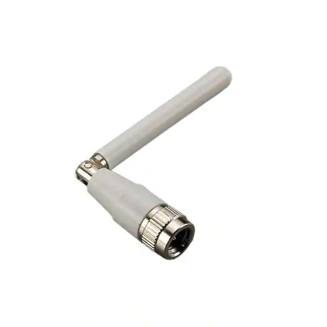
TG.09.0113W
Product Name
:
Penta-band Cellular Hinged SMA Male Monopole
Feature
:
700MHz to 3800MHz
GSM/CDMA/HSPA/UMTS
700*/850/900/1700/1800/1900/2100/2300/3500/3700
Rotatable hinge design for optimal reception
Top quality housing with brass hinge and connector
Extended operation temperature range
RoHS Compliant
SPE-11-8-034/E/SS
Page 1 of 37
�1. Introduction
The TG.09 Penta-band Cellular Hinged Rotatable SMA antenna is a high efficiency
monopole antenna. Compared to other much larger antennas on the market, it has
superior wide-band high efficiency characteristics. This antenna is used by many of the
leading wireless device providers in the world marketplace.
The unique rotatable hinge design enables the user to rotate the antenna to the best
angle for an optimal cellular signal reception.
As the upper antenna element can
move in any direction, it also reduces damage from impact force from any angle to the
antenna, compared to traditional hinged right angle or fixed fight angle designs or
straight antennas.
The tiny dimensions of this antenna coupled with excellent RF performance and an
aesthetic high end design feel make it the ideal cellular antenna for routers, vehicle
tracking devices, telematics devices, remote monitoring systems, POS devices.
The TG.09 as all monopole antennas works best connected directly to the
ground-plane of the device main-board. Taoglas offers support services to
characterize antenna efficiency on your individual device ground-plane.
The TG.09 antenna also supports LTE 700MHz band applications when it is directly
connected to ground-planes with lengths above 60mm.
Please contact Taoglas regional support centre first if you wish to do PTCRB or network
approvals with this antenna attached to your device, so we can check RF integration is
correct and do a pre-test first to ensure optimized passive and active performance and
a smooth and quick certification approval process.
This antenna also comes in a black housing version. TG.09.0113
SPE-11-8-034/E/SS
Page 2 of 37
�2. Specification
ELECTRICAL
Communication
System
Frequency (MHz)
Efficiency (free
space)*
Gain (dBi, free
space)*
Efficiency
(mounted on
PCB)*
Gain (dBi,
mounted on PCB)*
Impedance
4G/3G/2G Cellular
700
LTE
703
~
803
1710
~
2170
2300
LTE
2300
~
2400
2700
LTE
2490
~
2690
3500
LTE
3400
~
3600
3700
LTE
3600
~
3800
30%
30%
17%
32%
28%
43%
0.9
0.9
0.9
-1.3
1.1
1.8
3.1
57%
61%
58%
54%
31%
59%
36%
37%
1.8
3.4
3.4
3.4
2.3
3.7
4.3
2.6
AMPS
GSM
DCS
PCS
UMTS
824
~
896
88
0~
960
1710
~
1880
1850
~
1990
18%
22%
22%
25%
-3.0
-2.6
-3.0
52%
58%
0.8
1.7
50Ω
Polarization
Linear
Radiation Pattern
Omnidirectional
Input Power
10W
Antenna Length
MECHANICAL
72 ± 1.5 mm
Antenna Diameter
10 ± 0.3 mm
Casing
POM
Connector
SMA Male (Brass)
Weight
8g
Temperature
Range
Storage
Temperature
Humidity
ENVIRONMENTAL
-40°C to 85°C
-40℃ ~ +85℃
Non-condensing 65°C 95% RH
* Average efficiency and peak gain of antenna sitting 180° in Free Space and on
150*90mm ground plane at the side of the PCB. Please refer to section 3 for testing
detail.
SPE-11-8-034/E/SS
Page 3 of 37
�3. Electrical Property – Return Loss
The TG.09 was measured and tested in four different environments
a. Free space
b. On the edge of a 150*90mm ground plane - common size for IoT devices. TG.09
is mounted on the 90mm edge for testing.
c. In the center of a 300*300mm ground plane – simulate the effect of mounting
in the center of a big ground plane.
d. On the edge of a 300*300mm ground plane - simulates the effect of mounting
TG.09 on top of a large gateway/router.
Straight Position
Free Space
150mm x 90mm
Ground Plane
300mm x 300mm
Ground Plane Edge
300mm x 300mm
Ground Pane Center
Antenna in 90° Bend Position
Free Space
150mm x 90mm
Ground Plane
300mm x 300mm
Ground Plane Edge
300mm x 300mm
Ground Pane Center
SPE-11-8-034/E/SS
Page 4 of 37
�Y
Z
Y
Z
X
X
Chamber Set-up
SPE-11-8-034/E/SS
Page 5 of 37
�3.1
Return Loss
0
Return Loss [dB]
-5
-10
-15
-20
-25
-30
-35
Free Space Straight
Free Space Bend
150mm x 90mm Straight
150mm x 90mm Bend
600 800 1000 1200 1400 1600 1800 2000 2200 2400 2600 2800 3000 3200 3400 3600 3800 4000
Frequency [MHz]
0
Return Loss [dB]
-5
-10
-15
-20
-25
300mm x 300mm Center Straight
300mm x 300mm Center Bend
-30
-35
300mm x 300mm Edge Straight
300mm x 300mm Edge Bend
600 800 1000 1200 1400 1600 1800 2000 2200 2400 2600 2800 3000 3200 3400 3600 3800 4000
Frequency [MHz]
SPE-11-8-034/E/SS
Page 6 of 37
�3.2
VSWR
10
Free Space Straight
9
Free Space Bend
8
150mm x 90mm Straight
150mm x 90mm Bend
VSWR
7
6
5
4
3
2
1
600 800 1000 1200 1400 1600 1800 2000 2200 2400 2600 2800 3000 3200 3400 3600 3800 4000
Frequency [MHz]
10
300mm x 300mm Center Straight
300mm x 300mm Center Bend
300mm x 300mm Edge Straight
300mm x 300mm Edge Bend
9
8
VSWR
7
6
5
4
3
2
1
600 800 1000 1200 1400 1600 1800 2000 2200 2400 2600 2800 3000 3200 3400 3600 3800 4000
Frequency [MHz]
SPE-11-8-034/E/SS
Page 7 of 37
�3.3
Efficiency
100
Free Space Straight
Free Space Bend
150mm x 90mm Straight
150mm x 90mm Bend
90
Efficiency [%]
80
70
60
50
40
30
20
10
0
700 900 1100 1300 1500 1700 1900 2100 2300 2500 2700 2900 3100 3300 3500 3700 3900
Frequency [MHz]
100
90
Efficiency [%]
80
70
60
50
40
30
300mm x 300mm Center Straight
300mm x 300mm Center Bend
300mm x 300mm Edge Straight
300mm x 300mm Edge Bend
20
10
0
700 900 1100 1300 1500 1700 1900 2100 2300 2500 2700 2900 3100 3300 3500 3700 3900
Frequency [MHz]
SPE-11-8-034/E/SS
Page 8 of 37
�Gain [dBi]
Peak Gain
6
5
4
3
2
1
0
-1
-2
-3
-4
-5
-6
-7
-8
-9
Free Space Straight
Free Space Bend
150mm x 90mm Straight
150mm x 90mm Bend
700 900 1100 1300 1500 1700 1900 2100 2300 2500 2700 2900 3100 3300 3500 3700 3900
Frequency [MHz]
8
7
6
5
4
Gain [dBi]
3.4
3
2
1
0
-1
300mm x 300mm Center Straight
300mm x 300mm Center Bend
300mm x 300mm Edge Straight
300mm x 300mm Edge Bend
-2
-3
-4
-5
700 900 1100 1300 1500 1700 1900 2100 2300 2500 2700 2900 3100 3300 3500 3700 3900
Frequency [MHz]
SPE-11-8-034/E/SS
Page 9 of 37
�3.5
Average Gain
0
-1
-2
Aver Gain [dB]
-3
-4
-5
-6
-7
-8
-9
Free Space Straight
Free Space Bend
150mm x 90mm Straight
150mm x 90mm Bend
-10
-11
-12
700 900 1100 1300 1500 1700 1900 2100 2300 2500 2700 2900 3100 3300 3500 3700 3900
Frequency [MHz]
0
-1
Aver Gain [dB]
-2
-3
-4
-5
-6
-7
-8
-9
-10
300mm x 300mm Center Straight
300mm x 300mm Center Bend
300mm x 300mm Edge Straight
300mm x 300mm Edge Bend
700 900 1100 1300 1500 1700 1900 2100 2300 2500 2700 2900 3100 3300 3500 3700 3900
Frequency [MHz]
SPE-11-8-034/E/SS
Page 10 of 37
�4. Radiation Patterns
4.1 TG.09 in Free Space – Straight
SPE-11-8-034/E/SS
Page 11 of 37
�4.2 TG.09 in Free Space – 90°
SPE-11-8-034/E/SS
Page 12 of 37
�4.3 TG.09 on 150*90mm Ground Plane – Straight
SPE-11-8-034/E/SS
Page 13 of 37
�4.4 TG.09 on 150*90mm Ground Plane – 90°
SPE-11-8-034/E/SS
Page 14 of 37
�4.5 TG.09 on 300*300mm Ground Plane Centre – Straight
SPE-11-8-034/E/SS
Page 15 of 37
�4.6 TG.09 on 300*300mm Ground Plane Centre – 90°
SPE-11-8-034/E/SS
Page 16 of 37
�4.7 TG.09 on 300*300mm Ground Plane Edge – Straight
SPE-11-8-034/E/SS
Page 17 of 37
�4.8 TG.09 on 300*300mm Ground Plane Edge – 90°
SPE-11-8-034/E/SS
Page 18 of 37
�5. 3D Radiated Pattern
5.1
Free Space – Straight
704MHz
751MHz
824MHz
960MHz
1710MHz
1880MHz
1990MHz
2170MHz
2300MHz
3400MHz
2500MHz
3500MHz
2690MHz
3600MHz
SPE-11-8-034/E/SS
Page 19 of 37
�5.2
Free Space – 90°
704MHz
751MHz
824MHz
1710MHz
1880MHz
1990MHz
2300MHz
3400MHz
2500MHz
3500MHz
960MHz
2690MHz
3600MHz
SPE-11-8-034/E/SS
Page 20 of 37
�5.3
150*90mm Ground Plane – Straight
704MHz
751MHz
824MHz
960MHz
1710MHz
1880MHz
1990MHz
2170MHz
2300MHz
2500MHz
2690MHz
2300MHz
2500MHz
2690MHz
SPE-11-8-034/E/SS
Page 21 of 37
�5.4
150*90mm Ground Plane – 90°
704MHz
751MHz
824MHz
960MHz
1710MHz
1880MHz
1990MHz
2170MHz
2300MHz
2500MHz
2690MHz
3400MHz
3500MHz
3600MHz
SPE-11-8-034/E/SS
Page 22 of 37
�5.5
300*300mm Ground Plane Center – Straight
704MHz
1710MHz
2300MHz
3400MHz
751MHz
824MHz
960MHz
1880MHz
1990MHz
2170MHz
2500MHz
3500MHz
2690MHz
3600MHz
SPE-11-8-034/E/SS
Page 23 of 37
�5.6
300*300mm Ground Plane Center – 90°
704MHz
1710MHz
751MHz
1880MHz
824MHz
960MHz
1990MHz
2170MHz
2300MHz
2500MHz
2690MHz
3400MHz
3500MHz
3600MHz
SPE-11-8-034/E/SS
Page 24 of 37
�5.7
300*300mm Ground Plane Edge – Straight
704MHz
751MHz
824MHz
960MHz
1710MHz
1880MHz
1990MHz
2170MHz
2300MHz
3400MHz
2500MHz
3500MHz
2690MHz
3600MHz
SPE-11-8-034/E/SS
Page 25 of 37
�5.8
300*300mm Ground Plane Edge – 90°
704MHz
751MHz
824MHz
960MHz
1710MHz
1880MHz
1990MHz
2170MHz
2300MHz
3400MHz
2500MHz
3500MHz
2690MHz
3600MHz
SPE-11-8-034/E/SS
Page 26 of 37
�6. Mechanical Drawing (Unit: mm)
1
Housing
POM Black
2
Hinge
Brass Ni Plated
3
Cap
POM Black
4
Connector
SMA Male (Brass)
SPE-11-8-034/E/SS
Page 27 of 37
�7. Installation
SPE-11-8-034/E/SS
Page 28 of 37
�8. Minimum Ground Plane for LTE Efficiency
Different Ground Plane lengths were considered for acceptable efficiency for LTE
bands.
Three different ground planes were chosen. They were all 30mm wide and the lengths
were varied beginning at 90mm then 70mm and finally 60mm
90*30mm
70*30mm
60*30mm
It was also considered whether the TG.09 antenna was positioned straight or at an
angle of 90°.
The antenna was positioned on the edge of the Ground Plane for all tests.
SPE-11-8-034/E/SS
Page 29 of 37
�Parameter
Straight Pose
Band
UMTS/
2300
2700
HSPA
LTE
LTE
1850~
1920~
2300~
2490~
1880
1990
2170
2400
2690
-3.2
-3.2
-1.9
-2.3
-5.1
72%
49%
48%
64%
59%
2.0
1.9
2.7
3.2
9
4.8
5.1
-2.7
-2.7
53%
700 LTE
GSM
DCS
PCS
703~
824~
1710~
803
960
-1.4
3500 LTE
3700LTE
3400~3600
3600~ 3800
-2.0
-3.8
-2.9
31%
63%
42%
54%
3.6
1.3
5.2
2.7
4.2
11.4
11.1
5.3
9.6
9.5
7.9
-3.4
-2.2
-1.8
-5.7
-1.5
-3.9
-2.0
54%
45%
60%
67%
28%
70%
42%
62%
1.8
2.0
1.5
3.5
4.3
1.7
4.3
3.7
5.0
Return Loss (dB)
7.3
7.1
4.2
7.3
12.4
4.4
14.7
8.9
9.9
Average Gain
(dBi)
-3.9
-2.9
-2.9
-2.4
-1.6
-7.3
-1.4
-4.3
-3.0
41%
50%
51%
58%
69%
20%
72%
37%
49%
1.1
1.3
2.1
3.0
4.1
0.4
4.5
3.0
4.5
6.5
7.7
5.0
6.4
9.9
3.4
12.4
6.3
6.4
Frequency (MHz)
Average Gain
(dBi)
Efficiency (%)
Peak Gain (dBi)
90*30mm
Ground
Return Loss (dB)
Average Gain
(dBi)
Efficiency (%)
Peak Gain (dBi)
Efficiency (%)
Peak Gain (dBi)
70* 30mm
Ground
60* 30mm
Ground
Return Loss (dB)
90° Bend Pose
Average Gain
(dBi)
Efficiency (%)
Peak Gain (dBi)
90*30mm
Ground
Return Loss (dB)
Average Gain
(dBi)
Efficiency (%)
Peak Gain (dBi)
70*30mm
Ground
Return Loss (dB)
Average Gain
(dBi)
Efficiency (%)
Peak Gain (dBi)
Return Loss (dB)
60*30mm
Ground
-1.7
-2.4
-3.5
-2.1
-2.1
-5.3
-2.1
-3.3
-2.6
68%
58%
45%
61%
61%
30%
61%
47%
54%
2.7
2.5
2.1
3.1
3.5
1.6
5.2
3.4
4.3
7.5
7.6
4.5
9.1
12.5
5.1
8.7
12.3
7.8
-4.2
-2.3
-3.7
-2.5
-1.8
-4.6
-1.5
-3.4
-2.0
39%
59%
42%
56%
67%
35%
70%
46%
62%
1.4
1.7
1.4
3.2
4.3
2.1
4.1
4.1
5.1
4.9
11.2
3.9
6.4
13.5
5.2
12.6
10.6
9.5
-5.6
-3.0
-3.2
-2.6
-1.7
-5.9
-1.4
-3.9
-3.1
28%
50%
47%
54%
68%
26%
73%
41%
49%
0.0
1.0
1.8
3.0
3.8
1.1
4.3
3.3
4.5
4.4
11.5
4.6
6.0
10.8
3.9
11.2
7.0
6.2
SPE-11-8-034/E/SS
Page 30 of 37
�8.1
Return Loss
0
Return Loss [dB]
-5
-10
-15
-20
90mm x 30mm Straight
-25
70mm x 30mm Straight
60mm x 30mm Straight
-30
700 900 1100 1300 1500 1700 1900 2100 2300 2500 2700 2900 3100 3300 3500 3700 3900
Frequency [MHz]
0
-5
Return Loss [dB]
-10
-15
-20
-25
-30
-35
-40
-45
90mm x 30mm Bend
70mm x 30mm Bend
60mm x 30mm Bend
-50
700 900 1100 1300 1500 1700 1900 2100 2300 2500 2700 2900 3100 3300 3500 3700 3900
Frequency [MHz]
SPE-11-8-034/E/SS
Page 31 of 37
�8.2
VSWR
30
90mm x 30mm Straight
70mm x 30mm Straight
25
60mm x 30mm Straight
VSWR
20
15
10
5
0
700 900 1100 1300 1500 1700 1900 2100 2300 2500 2700 2900 3100 3300 3500 3700 3900
Frequency [MHz]
25
90mm x 30mm Bend
70mm x 30mm Bend
VSWR
20
60mm x 30mm Bend
15
10
5
0
700 900 1100 1300 1500 1700 1900 2100 2300 2500 2700 2900 3100 3300 3500 3700 3900
Frequency [MHz]
SPE-11-8-034/E/SS
Page 32 of 37
�8.3
Efficiency for Straight Antenna
100
90
80
Efficiency [%]
70
60
50
40
30
20
10
90mm x 30mm Straight
70mm x 30mm Straight
60mm x 30mm Straight
0
700 900 1100 1300 1500 1700 1900 2100 2300 2500 2700 2900 3100 3300 3500 3700
Frequency [MHz]
Peak Gain for Straight Antenna
6
5
4
3
Gain [dBi]
8.4
2
1
0
-1
-2
-3
-4
90mm x 30mm Straight
70mm x 30mm Straight
60mm x 30mm Straight
700 900 1100 1300 1500 1700 1900 2100 2300 2500 2700 2900 3100 3300 3500 3700
Frequency [MHz]
SPE-11-8-034/E/SS
Page 33 of 37
�8.5
Average Gain for Straight Antenna
0
-1
Aver Gain [dB]
-2
-3
-4
-5
-6
-7
90mm x 30mm Straight
-8
70mm x 30mm Straight
60mm x 30mm Straight
-9
700 900 1100 1300 1500 1700 1900 2100 2300 2500 2700 2900 3100 3300 3500 3700
Frequency [MHz]
8.6
Efficiency for 90° Bend
100
90
Efficiency [%]
80
70
60
50
40
30
90mm x 30mm Bend
20
70mm x 30mm Bend
10
60mm x 30mm Bend
0
700
900 1100 1300 1500 1700 1900 2100 2300 2500 2700 2900 3100 3300 3500 3700
Frequency [MHz]
SPE-11-8-034/E/SS
Page 34 of 37
�8.7
Peak Gain for 90° Bend
6
5
4
3
Gain [dBi]
2
1
0
-1
-2
-3
-4
-5
-6
-7
90mm x 30mm Bend
70mm x 30mm Bend
60mm x 30mm Bend
700 900 1100 1300 1500 1700 1900 2100 2300 2500 2700 2900 3100 3300 3500 3700
Frequency [MHz]
8.8
Average Gain for 90° Bend
0
-1
Aver Gain [dB]
-2
-3
-4
-5
-6
-7
-8
-9
-10
90mm x 30mm Bend
70mm x 30mm Bend
60mm x 30mm Bend
700 900 1100 1300 1500 1700 1900 2100 2300 2500 2700 2900 3100 3300 3500 3700
Frequency [MHz]
SPE-11-8-034/E/SS
Page 35 of 37
�9. Packaging
SPE-11-8-034/E/SS
Page 36 of 37
�Taoglas makes no warranties based on the accuracy or completeness of the contents of this document and
reserves the right to make changes to specifications and product descriptions at any time without notice.
Taoglas reserves all rights to this document and the information contained herein.
Reproduction, use or disclosure to third parties without express permission is strictly prohibited.
Copyright © Taoglas Ltd.
SPE-11-8-034/E/SS
Page 37 of 37
�
很抱歉,暂时无法提供与“TG.09.0113W”相匹配的价格&库存,您可以联系我们找货
免费人工找货