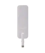
SPECIFICATION
Part No.
:
TG.35.8113W
Product Name
:
Apex II – White Hinged TG.35
Ultra-Wideband 4G LTE Antenna
Features
:
Highest efficiency for worldwide LTE and Wi-Fi
LTE / HSPA / GSM / CDMA /DCS /PCS / WCDMA / UMTS /
GPRS / EDGE /GPS /Wi-Fi
Dims: 224*58mm
698MHz to 960MHz, 1575.42MHz
1710MHz to 2700Mhz
5150MHz to 5850MHz
Dipole Swivel Terminal Antenna
Hinged 90° termination with SMA(M) Connector
Enhanced hinge structure for vibration environment
Connector customizable
RoHS Compliant
Photo:
SPE-14-8-083/E/PK
Page 1 of 71
�1. Introduction
The hinged Apex II TG.35 Ultra-Wideband Dipole Antenna has been designed to cover
all Cellular, ISM and Wi-Fi working frequencies in the 700-6000MHz spectrum.
Evolved from the already highly successful Apex TG.30, this second generation has
the highest wide-band efficiency in its range of any terminal antenna on the market
today.
The Apex II has been primarily designed for use with 4G LTE modules and devices
that require the highest possible efficiency and peak gain to deliver best in class
throughput on all major cellular (2G/3G/4G) bands worldwide for access points,
terminals and routers. High efficiency is vital for applications such as high speed video
and real-time streaming, or high capacity MIMO networks on public transportation.
This attractive slim-line antenna is ground plane independent, meaning it does not
need to be connected to the ground-plane of a device to radiate efficiently, on the
other hand neither is it seriously detuned by connecting to a ground-plane, thus
avoiding a problem notorious to smaller antennas.
It comes with an SMA(M) connector and swivel mechanism that allows the antenna
part to be rotated to fit in tight environments. The 90° hinge structure has been
improved and strengthened so that the antenna in a 90° position would not fall down
to 180° in vibration environment.
The Apex II is backward compatible with 3G and 2G cellular applications such as HSPA,
GSM, GPRS, UMTS, Wi-Fi and even has GPS included for Assisted GPS and/or E911
applications.
In summary the Apex II is the ideal solution for any device requiring high, reliable
performance. It will meet most type approval or carrier certification requirements
from an efficiency standpoint. The antenna also makes an excellent reference antenna
for test purposes. It has been designed as an omni-directional antenna and the
radiation patterns prove this, being stable across all bands.
Connector type is customizable. Housing is also available in black. Contact Taoglas
regional sales office for more information.
SPE-14-8-083/E/PK
Page 2 of 71
�2. Specification
ELECTRICAL
LTE/GSM/CDMA GPS/GLONAS
Standard
Frequency (MHz)
700/850/900
S
698~960
1565~1612
LTE/GSM/HSPA/CD
MA
1700/1800/1900
1710~1990
UMTS/HSPA
Wi-Fi
LTE
Wi-Fi
2100
2400
2600
5800
2500~2700
4800~6000
1920~2170 2400~2500
Efficiency (%)
In free space
On 150*90mm ground plane
edge
On 30*30cm ground plane center
On 30*30cm ground plane edge
straight
53.92
55.66
64.44
62.55
49.61
53.14
56.35
bent
56.51
55.19
68.87
68.72
53.41
54.11
55.84
straight
84.72
66.85
71.00
71.43
56.21
52.22
51.59
bent
80.92
71.38
71.62
71.14
52.81
53.28
51.82
straight
59.06
51.56
62.34
61.21
67.43
53.51
51.25
bent
57.15
36.67
52.88
57.70
60.70
58.10
56.74
straight
59.62
48.19
65.51
64.78
63.28
56.84
56.30
bent
53.18
41.91
63.43
62.24
62.99
46.66
47.09
Average Gain(dBi)
In free space
On 150*90mm ground plane
edge
On 30*30cm ground plane center
On 30*30cm ground plane center
straight
-2.71
-2.55
-1.91
-2.05
-3.05
-2.76
-2.59
bent 90°
-2.50
-2.61
-1.63
-1.64
-2.72
-2.67
-2.63
straight
-0.74
-1.75
-1.50
-1.46
-2.50
-2.82
-2.92
bent 90°
-0.96
-1.46
-1.45
-1.48
-2.77
-2.74
-2.89
straight
-2.31
-2.88
-2.06
-2.13
-1.74
-2.72
-2.94
bent 90°
-2.44
-4.36
-2.78
-2.40
-2.18
-2.37
-2.52
straight
-2.26
-3.17
-1.85
-1.89
-2.01
-2.45
-2.58
bent 90°
-2.81
-3.78
-1.99
-2.08
-2.02
-3.32
-3.37
straight
4.42
1.59
3.15
2.70
4.93
4.43
2.55
Peak Gain(dBi)
In free space
bent
3.16
1.64
3.37
3.34
3.28
3.06
2.09
On the 150*90mm ground plane
edge
straight
3.28
3.70
4.79
5.02
2.50
2.36
2.67
bent
2.77
3.24
4.07
4.35
4.47
3.80
2.68
On the 30*30cm ground plane
center
straight
6.37
0.75
3.34
3.39
6.44
6.92
5.29
bent
6.47
5.12
6.27
6.44
5.78
8.14
6.05
On the 30*30cm ground plane
center
straight
4.87
1.70
3.62
4.01
4.63
6.02
4.87
bent
4.78
4.07
5.95
5.45
5.87
3.89
4.59
straight
4.42
1.59
3.15
2.70
4.93
4.43
2.55
bent
3.16
1.64
3.37
3.34
3.28
3.06
2.09
In free space
Impedance
50Ω
Polarization
Linear
Radiation Pattern
Omni
Input Power
5W
SPE-14-8-083/E/PK
Page 3 of 71
�MECHANICAL
Casing
UV Resistant PC/ABS
Connector
SMA Male Hinged 90°
Weight
75g
Recommended Torque for Mounting
0.9 N∙m
Max torque for Mounting
1.176 N∙m
ENVIRONMENTAL
Temperature Range
-40°C to 85°C
Humidity
Non-condensing 65°C 95% RH
SPE-14-8-083/E/PK
Page 4 of 71
�3. Antenna Characteristics
3.1 Testing setup
In free space
Antenna straight
Antenna bent 90°
On 150*90mm ground plane edge
Antenna straight
Antenna bent 90°
SPE-14-8-083/E/PK
Page 5 of 71
�On 30*30cm ground plane center
Antenna straight
Antenna bent 90°
On 30*30cm ground plane edge
Antenna straight
Antenna bent 90°
SPE-14-8-083/E/PK
Page 6 of 71
�3.2
Return Loss
In free space
On 150*90mm ground plane edge
SPE-14-8-083/E/PK
Page 7 of 71
�On 30*30cm ground plane center
On 30*30cm ground plane edge
SPE-14-8-083/E/PK
Page 8 of 71
�3.3
Peak Gain
SPE-14-8-083/E/PK
Page 9 of 71
�3.4
Efficiency
SPE-14-8-083/E/PK
Page 10 of 71
�3.5
Average Gain
SPE-14-8-083/E/PK
Page 11 of 71
�4. Antenna Radiation Patterns
4.1 Antenna setup
Y
X
Z
Antenna straight in the free space
SPE-14-8-083/E/PK
Page 12 of 71
�4.2 Antenna radiation patterns
4.2.1 Antenna straight in free space
XY plane
Y
330
300
270
5
0
-5
-10
-15
-20
-25
-30
-35
-40
0
30
60
90
240
120
210
XZ plane
X
704MHz
751MHz
824MHz
880MHz
960MHz
150
180
(dBi)
Z
X
SPE-14-8-083/E/PK
Page 13 of 71
�YZ plane
Z
330
300
270
5
0
-5
-10
-15
-20
-25
-30
-35
-40
0
30
60
90
240
Y
120
210
704MHz
751MHz
824MHz
880MHz
960MHz
150
180
(dBi)
XY plane
Y
330
300
270
5
0
-5
-10
-15
-20
-25
-30
-35
-40
0
30
60
90
240
120
210
150
180
(dBi)
X
1710MHz
1800MHz
1990MHz
2170MHz
SPE-14-8-083/E/PK
Page 14 of 71
�XZ plane
Z
X
YZ plane
Z
330
300
270
5
0
-5
-10
-15
-20
-25
-30
-35
-40
0
30
60
90
240
Y
120
210
150
180
(dBi)
1710MHz
1880MHz
1990MHz
2170MHz
SPE-14-8-083/E/PK
Page 15 of 71
�XY plane
Y
330
300
270
5
0
-5
-10
-15
-20
-25
-30
-35
-40
0
30
60
90
240
X
120
210
2300MHz
2500MHz
2570MHz
2700MHz
150
180
(dBi)
XZ plane
Z
X
SPE-14-8-083/E/PK
Page 16 of 71
�YZ plane
Z
Y
XY plane
Y
330
300
270
5
0
-5
-10
-15
-20
-25
-30
-35
-40
0
30
60
90
240
120
210
150
180
(dBi)
X
4900MHz
5150MHz
5350MHz
5650MHz
5850MHz
SPE-14-8-083/E/PK
Page 17 of 71
�XZ plane
Z
X
YZ plane
Z
Y
SPE-14-8-083/E/PK
Page 18 of 71
�4.3 Antenna setup
Y
X
Z
Antenna bent 90° in free space
SPE-14-8-083/E/PK
Page 19 of 71
�4.4 Antenna radiation patterns
4.4.1 Antenna bent 90° in free space
XY plane
Y
X
XZ plane
Z
X
SPE-14-8-083/E/PK
Page 20 of 71
�Z
YZ plane
330
300
270
5
0
-5
-10
-15
-20
-25
-30
-35
-40
0
30
60
90
240
Y
120
210
704MHz
751MHz
824MHz
880MHz
960MHz
150
180
(dBi)
XY plane
Y
X
SPE-14-8-083/E/PK
Page 21 of 71
�XZ plane
Z
330
300
270
5
0
-5
-10
-15
-20
-25
-30
-35
-40
0
30
60
90
240
X
120
210
1710MHz
1880MHz
1990MHz
2170MHz
150
180
(dBi)
YZ plane
Z
Y
SPE-14-8-083/E/PK
Page 22 of 71
�XY plane
Y
X
XZ plane
Z
330
300
270
5
0
-5
-10
-15
-20
-25
-30
-35
-40
0
30
60
90
240
120
210
150
180
X
2300MHz
2500MHz
2570MHz
2700MHz
(dBi)
SPE-14-8-083/E/PK
Page 23 of 71
�YZ plane
Z
330
300
270
5
0
-5
-10
-15
-20
-25
-30
-35
-40
0
30
60
90
240
Y
120
210
2300MHz
2500MHz
2570MHz
2700MHz
150
180
(dBi)
XY plane
Y
X
SPE-14-8-083/E/PK
Page 24 of 71
�XZ plane
Z
330
300
270
5
0
-5
-10
-15
-20
-25
-30
-35
-40
0
30
60
90
240
X
120
210
4900MHz
5150MHz
5350MHz
5650MHz
5850MHz
150
(dBi)
180
YZ plane
Z
330
300
270
5
0
-5
-10
-15
-20
-25
-30
-35
-40
0
30
60
90
240
120
210
150
180
(dBi)
Y
4900M
Hz
5150M
Hz
SPE-14-8-083/E/PK
Page 25 of 71
�4.5 Antenna setup
Y
X
Z
Antenna bent 90° with 90*150mm ground plane
SPE-14-8-083/E/PK
Page 26 of 71
�4.6 Antenna radiation patterns
4.6.1 Antenna bent 90° with 90*150mm ground plane
XY plane
Y
X
XZ plane
Z
X
SPE-14-8-083/E/PK
Page 27 of 71
�YZ plane
Z
330
300
270
5
0
-5
-10
-15
-20
-25
-30
-35
-40
0
30
60
90
240
120
210
704MHz
751MHz
824MHz
880MHz
150
180
XY plane
Y
(dBi)
Y
X
SPE-14-8-083/E/PK
Page 28 of 71
�XZ plane
Z
330
300
270
5
0
-5
-10
-15
-20
-25
-30
-35
-40
0
30
60
90
240
X
120
210
1710MHz
1880MHz
1990MHz
2170MHz
150
180
(dBi)
YZ plane
Z
Y
SPE-14-8-083/E/PK
Page 29 of 71
�XY plane
Y
X
XZ plane
Z
330
300
270
5
0
-5
-10
-15
-20
-25
-30
-35
-40
0
30
60
90
240
X
120
210
150
180
2300MHz
2500MHz
2570MHz
2700MHz
(dBi)
SPE-14-8-083/E/PK
Page 30 of 71
�YZ plane
Z
330
300
270
5
0
-5
-10
-15
-20
-25
-30
-35
-40
0
30
60
90
240
120
210
2300MHz
2500MHz
2570MHz
2700MHz
150
180
XY plane
Y
(dBi)
Y
X
SPE-14-8-083/E/PK
Page 31 of 71
�XZ plane
Z
330
300
270
5
0
-5
-10
-15
-20
-25
-30
-35
-40
0
30
60
90
240
120
210
150
180
YZ plane
X
4900MHz
5150MHz
5350MHz
5650MHz
5850MHz
(dBi)
Z
330
300
270
5
0
-5
-10
-15
-20
-25
-30
-35
-40
0
30
60
90
240
120
210
150
180
Y
4900M
Hz
5150M
Hz
(dBi)
SPE-14-8-083/E/PK
Page 32 of 71
�4.7 Antenna setup
Y
X
Z
Antenna bent 90° with 90*150mm ground plane
SPE-14-8-083/E/PK
Page 33 of 71
�4.8 Antenna radiation patterns
4.8.1 Antenna bent 90° with 90*150mm ground plane
XY plane
Y
X
XZ plane
Z
X
SPE-14-8-083/E/PK
Page 34 of 71
�YZ plane
Z
330
300
270
5
0
-5
-10
-15
-20
-25
-30
-35
-40
0
30
60
90
240
Y
120
210
704MHz
751MHz
824MHz
880MHz
150
180
(dBi)
XY plane
Y
X
SPE-14-8-083/E/PK
Page 35 of 71
�XZ plane
Z
330
300
270
5
0
-5
-10
-15
-20
-25
-30
-35
-40
0
30
60
90
240
120
210
1710MHz
1880MHz
1990MHz
2170MHz
150
180
YZ plane
X
(dBi)
Z
Y
SPE-14-8-083/E/PK
Page 36 of 71
�XY plane
Y
X
XZ plane
Z
330
300
270
5
0
-5
-10
-15
-20
-25
-30
-35
-40
0
30
60
90
240
X
120
210
150
180
2300MHz
2500MHz
2570MHz
2700MHz
(dBi)
SPE-14-8-083/E/PK
Page 37 of 71
�YZ plane
Z
330
300
270
5
0
-5
-10
-15
-20
-25
-30
-35
-40
0
30
60
90
240
Y
120
210
2300MHz
2500MHz
2570MHz
2700MHz
150
180
(dBi)
XY plane
Y
X
SPE-14-8-083/E/PK
Page 38 of 71
�XZ plane
Z
330
300
270
5
0
-5
-10
-15
-20
-25
-30
-35
-40
0
30
60
90
240
X
120
210
4900MHz
5150MHz
5350MHz
5650MHz
5850MHz
150
180
YZ plane
(dBi)
Z
330
300
270
5
0
-5
-10
-15
-20
-25
-30
-35
-40
0
30
60
90
240
120
210
150
180
Y
4900M
Hz
5150M
Hz
(dBi)
SPE-14-8-083/E/PK
Page 39 of 71
�4.9 Antenna setup
Y
X
Z
Antenna straight with 30*30cm ground plane center
SPE-14-8-083/E/PK
Page 40 of 71
�4.10 Antenna radiation patterns
4.10.1 Antenna straight with 30*30cm ground plane center
XY plane
Y
X
XZ plane
Z
X
SPE-14-8-083/E/PK
Page 41 of 71
�YZ plane
Z
330
300
270
5
0
-5
-10
-15
-20
-25
-30
-35
-40
0
30
60
90
240
120
210
704MHz
751MHz
824MHz
880MHz
150
180
XY plane
Y
(dBi)
Y
X
SPE-14-8-083/E/PK
Page 42 of 71
�XZ plane
Z
330
300
270
5
0
-5
-10
-15
-20
-25
-30
-35
-40
0
30
60
90
240
120
210
1710MHz
1880MHz
1990MHz
2170MHz
150
180
YZ plane
X
(dBi)
Z
Y
SPE-14-8-083/E/PK
Page 43 of 71
�XY plane
Y
X
XZ plane
Z
330
300
270
5
0
-5
-10
-15
-20
-25
-30
-35
-40
0
30
60
90
240
X
120
210
150
180
2300MHz
2500MHz
2570MHz
2700MHz
(dBi)
SPE-14-8-083/E/PK
Page 44 of 71
�YZ plane
Z
330
300
270
5
0
-5
-10
-15
-20
-25
-30
-35
-40
0
30
60
90
240
Y
120
210
2300MHz
2500MHz
2570MHz
2700MHz
150
180
(dBi)
XY plane
Y
X
SPE-14-8-083/E/PK
Page 45 of 71
�XZ plane
Z
330
300
270
0
5
0
-5
-10
-15
-20
-25
-30
-35
-40
30
60
90
240
120
210
4900MHz
5150MHz
5350MHz
5650MHz
5850MHz
150
180
X
(dBi)
YZ plane
Z
330
300
270
5
0
-5
-10
-15
-20
-25
-30
-35
-40
0
30
60
90
240
120
210
150
180
Y
4900M
Hz
5150M
Hz
(dBi)
SPE-14-8-083/E/PK
Page 46 of 71
�4.11 Antenna setup
Y
X
Z
Antenna bent 90° with 30*30cm ground plane center
SPE-14-8-083/E/PK
Page 47 of 71
�4.12 Antenna radiation patterns
4.12.1 Antenna bent 90° with 30*30cm ground plane center
XY plane
Y
X
XZ plane
Z
X
SPE-14-8-083/E/PK
Page 48 of 71
�YZ plane
Z
330
300
270
10
5
0
-5
-10
-15
-20
-25
-30
-35
-40
0
30
60
90
240
Y
120
210
704MHz
751MHz
824MHz
880MHz
150
180
(dBi)
XY plane
Y
X
SPE-14-8-083/E/PK
Page 49 of 71
�XZ plane
Z
330
300
270
10
5
0
-5
-10
-15
-20
-25
-30
-35
-40
0
30
60
90
240
X
120
210
1710MHz
1880MHz
1990MHz
2170MHz
150
180
(dBi)
YZ plane
Z
Y
SPE-14-8-083/E/PK
Page 50 of 71
�XY plane
Y
X
XZ plane
Z
330
300
270
10
5
0
-5
-10
-15
-20
-25
-30
-35
-40
0
30
60
90
240
X
120
210
150
180
2300MHz
2500MHz
2570MHz
2700MHz
(dBi)
SPE-14-8-083/E/PK
Page 51 of 71
�YZ plane
Z
330
300
270
10
5
0
-5
-10
-15
-20
-25
-30
-35
-40
0
30
60
90
240
Y
120
210
2300MHz
2500MHz
2570MHz
2700MHz
150
180
(dBi)
XY plane
Y
X
SPE-14-8-083/E/PK
Page 52 of 71
�XZ plane
Z
330
300
270
10
5
0
-5
-10
-15
-20
-25
-30
-35
-40
0
30
60
90
240
120
210
150
180
X
4900MHz
5150MHz
5350MHz
5650MHz
5850MHz
(dBi)
YZ plane
Z
330
300
270
10
5
0
-5
-10
-15
-20
-25
-30
-35
-40
0
30
60
90
240
120
210
150
180
Y
4900M
Hz
5150M
Hz
(dBi)
SPE-14-8-083/E/PK
Page 53 of 71
�4.13 Antenna setup
Y
X
Z
Antenna straight with 30*30cm ground plane edge
SPE-14-8-083/E/PK
Page 54 of 71
�4.14 Antenna radiation patterns
4.14.1 Antenna straight with 30*30cm ground plane edge
XY plane
Y
X
XZ plane
Z
X
SPE-14-8-083/E/PK
Page 55 of 71
�YZ plane
Z
330
300
270
5
0
-5
-10
-15
-20
-25
-30
-35
-40
0
30
60
90
240
Y
120
210
704MHz
751MHz
824MHz
880MHz
960MHz
150
180
(dBi)
XY plane
Y
X
SPE-14-8-083/E/PK
Page 56 of 71
�XZ plane
Z
330
300
270
5
0
-5
-10
-15
-20
-25
-30
-35
-40
0
30
60
90
240
120
210
1710MHz
1880MHz
1990MHz
2170MHz
150
180
YZ plane
X
(dBi)
Z
Y
SPE-14-8-083/E/PK
Page 57 of 71
�XY plane
Y
X
XZ plane
Z
330
300
270
5
0
-5
-10
-15
-20
-25
-30
-35
-40
0
30
60
90
240
120
210
150
180
X
2300MHz
2500MHz
2570MHz
2700MHz
(dBi)
SPE-14-8-083/E/PK
Page 58 of 71
�Z
YZ plane
330
300
270
5
0
-5
-10
-15
-20
-25
-30
-35
-40
0
30
60
90
240
120
210
150
180
Y
2300MHz
2500MHz
2570MHz
2700MHz
(dBi)
XY plane
Y
X
SPE-14-8-083/E/PK
Page 59 of 71
�XZ plane
Z
330
300
270
5
0
-5
-10
-15
-20
-25
-30
-35
-40
0
30
60
90
240
120
210
150
(dBi)
180
YZ plane
X
4900MHz
5150MHz
5350MHz
5650MHz
5850MHz
Z
330
300
270
5
0
-5
-10
-15
-20
-25
-30
-35
-40
0
30
60
90
240
120
210
150
180
(dBi)
Y
4900M
Hz
5150M
Hz
SPE-14-8-083/E/PK
Page 60 of 71
�4.15 Antenna setup
Y
X
Z
Antenna bent 90° with 30*30cm ground plane edge
SPE-14-8-083/E/PK
Page 61 of 71
�4.16 Antenna radiation patterns
4.16.1 Antenna bent 90° with 30*30cm ground plane edge
XY plane
Y
X
XZ plane
Z
X
SPE-14-8-083/E/PK
Page 62 of 71
�YZ plane
Z
330
300
270
10
5
0
-5
-10
-15
-20
-25
-30
-35
-40
0
30
60
90
240
120
210
704MHz
751MHz
824MHz
880MHz
960MHz
150
180
XY plane
Y
(dBi)
Y
X
SPE-14-8-083/E/PK
Page 63 of 71
�XZ plane
Z
330
300
270
5
0
-5
-10
-15
-20
-25
-30
-35
-40
0
30
60
90
240
X
120
210
1710MHz
1880MHz
1990MHz
2170MHz
150
180
(dBi)
YZ plane
Z
Y
SPE-14-8-083/E/PK
Page 64 of 71
�XY plane
Y
X
XZ plane
Z
330
300
270
5
0
-5
-10
-15
-20
-25
-30
-35
-40
0
30
60
90
240
120
210
150
180
X
2300MHz
2500MHz
2570MHz
2700MHz
(dBi)
SPE-14-8-083/E/PK
Page 65 of 71
�YZ plane
Z
330
300
270
5
0
-5
-10
-15
-20
-25
-30
-35
-40
0
30
60
90
240
Y
120
210
2300MHz
2500MHz
2570MHz
2700MHz
150
180
(dBi)
XY plane
Y
X
SPE-14-8-083/E/PK
Page 66 of 71
�XZ plane
Z
330
300
270
0
5
0
-5
-10
-15
-20
-25
-30
-35
-40
30
60
90
X
240
120
210
4900MHz
5150MHz
5350MHz
5650MHz
5850MHz
150
(dBi)
180
YZ plane
Z
330
300
270
5
0
-5
-10
-15
-20
-25
-30
-35
-40
0
30
60
90
240
120
210
150
180
(dBi)
Y
4900M
Hz
5150M
Hz
SPE-14-8-083/E/PK
Page 67 of 71
�5. Installation
SPE-14-8-083/E/PK
Page 68 of 71
�6. DRAWING
SPE-14-8-083/E/PK
Page 69 of 71
�7. Packaging
SPE-14-8-083/E/PK
Page 70 of 71
�SPE-14-8-083/E/PK
Page 71 of 71
�
很抱歉,暂时无法提供与“TG.35.8113W”相匹配的价格&库存,您可以联系我们找货
免费人工找货- 国内价格
- 1+499.50000
- 200+199.30320
- 500+192.65040
- 1000+189.35640