LP150-001 FIXTURE CONTROL MODULE
0-10V CONTROL
Load Ratings: 3A, @ 100-277V (305V Max)
WARNING AND CAUTIONS:
WARNINGS AND CAUTIONS:
• TO AVOID FIRE, SHOCK, OR DEATH; TURN OFF POWER AT CIRCUIT BREAKER OR FUSE AND TEST THAT POWER IS OFF
• Disconnect power at circuit breaker or fuse when servicing, installing or removing fixture or changing lamps.
BEFORE WIRING!
• Risk of Electric Shock - More than one disconnect switch may be required to de-energize the equipment before servicing.
• To be installed and/or used in accordance with appropriate electrical codes and regulations.
• Use this device with copper or copper clad wire only.
• If you are unsure about any part of these instructions, consult an electrician.
INSTALLATION GUIDE
DESCRIPTION
GOOD
LED Driver or
Dimmable Fixture
White
The Synapse LP150-001 controls lighting in commercial and
industrial buildings using the SNAP® wireless mesh network.
It provides On/Off capability via an internal relay and 0-10V
analog dimming control using a standard dimming protocol.
Synapse lighting controllers are controlled through a browserbased interface available via Synapse’s SimplySNAP lighting
solution.
AC Load
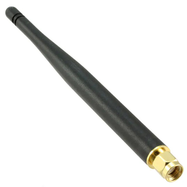
Antenna
Direction
FEATURES
•
•
•
BAD
LP150-001
Black
White
SPECIFICATIONS
Relay Max Switched Circuit: Zero Cross, 3A
Voltage Input: 100-277VAC, (+/- 10%), 50/60 Hz
Power Consumption (No Load): 8W @ 277V, 3.6W@120V
Power Output (Max): 305V
Dim Control Max Load: 30 mA Source/Sink
Radio Frequency: 2.4 GHz (IEEE 802.15.4)
RF Transmission Output Power: +15dBM
Operating Temperature: -40 to +55 C
Operating Humidity: 10 to 90%, non-condensing
Dimensions: 5.275”L x 2.175”W X 1.375”H (13.4 X 5.5 X 3.5 cm)
Enclosure Type: UL 94V-0, 5VA ABS Plastic
Configuration/Programming: Stored in non-volatile memory
FCC ID: U9O-RF200 IC ID: 7048A-RF200
INSTALLATION INSTRUCTIONS
2.
3.
4.
5.
Disconnect the hot wire (black) to the LED Fixture and connect it to the
black wire on the LP150-001.
Connect blue wire from LP150-001 to black wire of the LED fixture.
Connect white wire from the LP150-001 to the system white wire/neutral.
Connect the white wire from the LED fixture to the system white wire/
neutral.
Note: Steps 7-10 are for Class 2 Dimming Control
6.
7.
8.
Connect the gray wire on the LED fixture to the gray wire on the LP150001.
Connect the purple wire on the LED fixture to the purple wire on the
LP150-001.
Switch power on to the fixture. Lights should be on.
CAUTION
•
•
•
•
•
LP150-001 controllers must be installed in accordance with national, state,
and local electrical codes and requirements
All work must be performed by qualified personnel
Disconnect all power before installation or service
Metal conduit connector must be grounded
Switched output (blue wire) is energized by default at power up
WIRING INSTRUCTIONS
WARNING: TO AVOID FIRE, SHOCK, OR DEATH: TURN OFF POWER at circuit
breaker or fuse and test that power is off before wiring!
WARNING: RISK OF ELECTRIC SHOCK - more than one disconnect switch
may be required to de-energize equipment before servicing.
WARNING: All existing wiring connectors must be replaced with new UL
listed wiring connectors. All wiring connectors must be correctly sized for the
application and the number and the size of the electrical conductors.
1.
Place LP150-001 in desired location and secure it using #8 sheet
metal screws or equivalent. Prior to mounting, make sure the antenna
is vertically oriented and located at least 12 inches from any metal
structures. (Figure 1)
REGULATORY INFORMATION AND CERTIFICATIONS
RF Exposure Statement: This equipment complies with FCC radiation exposure
limits set forth for an uncontrolled environment. This equipment should be
installed and operated with minimum distance of 20cm between the radiator
and your body. This transmitter must not be co-located or operating in
conjunction with any other antenna or transmitter.
Industry Canada (IC) certifications: This digital apparatus does not exceed
the Class B limits for radio noise emissions from digital apparatus set
out in the Radio Interference Regulations of the Canadian Department of
Communications.
Le present appareil numerique n’emet pas de bruits radioelectriques depassant
les limites applicable aux appareils numeriques de la class B prescrites dans
le Reglement sur le brouillage radioelectrique edicte par le ministere des
Communications du Canada.
Note: When switched on, lamps should turn on to full brightness; approximately
10 VDC signal on the violet wire using the gray wire as reference.
FCC certifications and regulatory information (USA only)
9.
FCC Part 15 Class B: This device complies with part 15 of the FCC rules.
Refer to the SNAPLighting.com or SimplySNAP User’s Manual for
information on commissioning the LP150-001.
DIMMING
Below are some recommendations for successful dimming using the LP150001. The dimming control wires are referenced as Dim+ (Purple) and Dim(Gray). The dimming signals have a Maximum voltage of 10V DC.
•
Use multi-strand 18 Gauge Wire for noise immunity and current capability
•
Do not ground the dimming wire. This is a return signal and is critical for
dimming.
•
Route the dimming wires away from AC lines.
•
Use good connection methods with properly sized connectors.
•
Eliminate excess wire between fixtures. Line length will cause voltage
drop.
•
Number of fixtures is dependent upon the following factors: dimming
current, current requirements for LED driver, length of wire, quality of
connection, and gauge of wire
•
Verify dimming capability via a test bed with the number of actual fixtures,
wire length, connectors, and wire gauge
Gray
Violet
Figure 2 - Wiring Diagram
Figure 1 - Antenna Orientation
RF Tip: When installing the LP150-001, consideration of antenna position and
interference is required to ensure optimum wireless signal strength.
Dim -
Blue
AC Line
AC Neutral
On/Off switching via relay, up to 3A load
0-10V dimming, up to 30mA source/sink
Weather proof IP65 enclosure
Dim +
Declaration of Conformity (FCC 96-208 & 95-19): Synapse Wireless, Inc.
declares that the product name “LP150-001-00” (Model # LP150-001) to which
this declaration relates, meet the requirements specified by the Federal
Communications Commission as detailed in the following specifications:
• Part 15, Subpart B, for Class B equipment
• FCC 96-208 as it applies to Class B personal computers and peripherals
• This product has been tested at an External Test Laboratory certified per
FCC rules and has been found to meet the FCC, Part 15, Emission Limits.
Documentation is on file and available from Synapse Wireless, Inc.
If the FCC ID for the module inside this product enclosure is not visible when
installed inside another device, then the outside of the device into which this
product is installed must also display a label referring to the enclosed module
FCC ID. Modifications (FCC 15.21): Changes or modifications to this equipment
not expressly approved by Synapse Wireless, Inc., may void the user’s authority
to operate this equipment.
Operation is subject to the following two conditions: (1) These devices may
not cause harmful interference, and (2) These devices must accept any
interference received, including interference that may cause harmful operation.
RADIO FREQUENCY INTERFERENCE (RFI) (FCC 15.105): This equipment has
been tested and found to comply with the limits for a Class B digital device,
pursuant to Part 15 of the FCC rules. These limits are designed to provide
reasonable protection against harmful interference in a residential installation.
This equipment generates, uses, and can radiate radio frequency energy
and, if not installed and used in accordance with the instructions, may cause
harmful interference to radio communications. However, there is no guarantee
that interference will not occur in a particular installation. If this equipment
does cause harmful interference to radio or television reception, which can be
determined by turning the equipment off and on, the user is encouraged to try
to correct the interference by one or more of the following measures: (1) Reorient or relocate the receiving antenna; (2) Increase the separation between
the equipment and the receiver; (3) Connect the equipment into an outlet on
a circuit different from that to which the receiver is connected; (4) Consult the
dealer or an experienced radio/TV technician for help.
116-031609-012-A000
�