GWLA.10
Description:
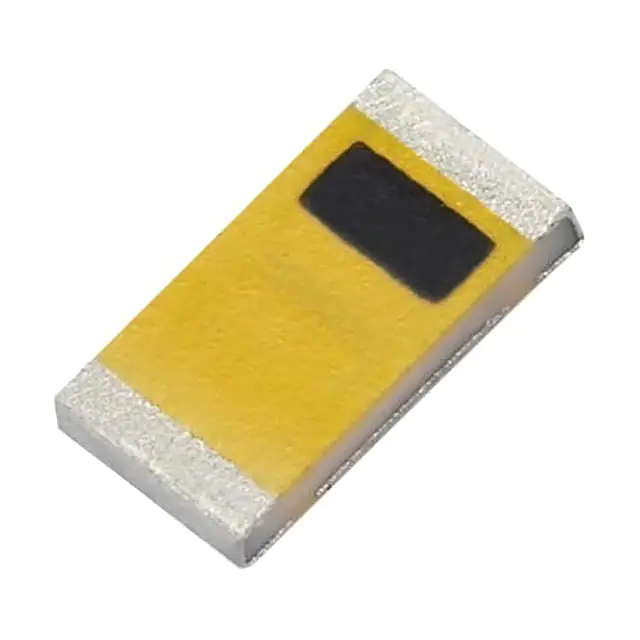
GWLA.10– GPS/GALILEO & Dual-Band Wi-Fi Ceramic Loop Antenna
Embedded 2in1 Structure
Features:
Small Footprint Embedded Loop Antenna
Omnidirectional
High Efficiency
Multi-Band Application - 1575.42MHz GPS/GALILEO and 2.4/5.8GHz Wi-Fi
Two Separate Feeds on one Antenna
Low profile
Surface-Mount)
Dimensions: 3.2*1.6*0.5mm
RoHS & Reach Compliant
SPE-16-8-049-D
�1.
Introduction
3
2.
Specifications
5
3.
Antenna Characteristics
7
4.
2D Radiation Patterns
11
5.
3D Radiation Patterns
14
6.
Mechanical Drawing
15
7
Matching Circuit
16
8
Soldering Conditions
17
9.
Packaging
18
Changelog
20
Taoglas makes no warranties based on the accuracy or completeness of the contents of this document and reserves the right to
make changes to specifications and product descriptions at any time without notice. Taoglas reserves all rights to this document and
the information contained herein. Reproduction, use or disclosure to third parties without express permission is strictly prohibited.
SPE-16-8-049-D
www.taoglas.com
2
�1.
Introduction
1.
Introduction
1.
Introduction
1.
Introduction
1.
Introduction
1.
Introduction
The GWLA.10 GPS/GALILEO and 2.4/5.8GHz 2in1 Embedded Ceramic Loop antenna is a high efficiency, miniature
SMD, edge mounted ceramic antenna for GPS/GALILEO and Wi-Fi, WLAN, ZigBee, Bluetooth, and 802.11ac
applications where PCB space is limited, such as hand-held devices. Rather than using two separate chip
antennas for GPS/GALILEO and Wi-Fi, the GWLA.10 has two separate antenna feeds in a single antenna body,
making it the ideal choice for applications where there is limited PCB space and where low cost is important.
The GWLA.10 uses the main PCB as its ground plane, thereby maintaining good efficiency despite its small size.
This compact size antenna can be tuned for different PCB sizes/environments by changing the values of the
matching circuit. This needs to be carefully calculated, contact a regional Taoglas facility for support. Also be
aware that smaller ground-planes will reduce the efficiency of the antenna.
1.
Introduction
At 3.2*1.6*0.5mm, the GWLA.10 is one of the smallest antennas available worldwide. This antenna is delivered
on tape and reel and manufactured in a TS16949 first tier automotive approved facility.
1.
Introduction
The GPS/GALILEO performance is excellent, with high efficiency and an omnidirectional pattern. The Wi-Fi
performance is also great and delivers stable efficiency and radiation pattern too, allowing this antenna to be
used in a huge variety of devices.
Typical Applications – Where GPS/GALILEO and Dual-Band Wi-Fi are required
Navigation or Position Tracking Systems
Handheld Devices
Tablets
POS Systems
Gateways and Routers
Mobile Wireless Camera Systems
OBD Devices
SPE-16-8-049-D
www.taoglas.com
3
�Many module manufacturers specify peak gain limits for any antennas that are to be connected to that
module. Those peak gain limits are based on free-space conditions. In practice, the peak gain of an antenna
tested in free-space can degrade by at least 1 or 2 dB when put inside a device. So ideally you should go for
a slightly higher peak gain antenna than mentioned on the module specification to compensate for this effect,
giving you better performance.
Upon testing of any of our antennas with your device and a selection of appropriate layout, integration
technique, or cable, Taoglas can make sure any of our antennas' peak gain will be below the peak gain limits.
Taoglas can then issue a specification and/or report for the selected antenna in your device that will clearly
show it complying with the peak gain limits, so you can be assured you are meeting regulatory requirements
for that module.
For example, a module manufacturer may state that the antenna must have less than 2 dBi peak gain, but
you do not need to select an embedded antenna that has a peak gain of less than 2 dBi in free-space. This
will give you a less optimized solution. It is better to go for a slightly higher free-space peak gain of 3 dBi or
more if available. Once that antenna gets integrated into your device, performance will degrade below this
2 dBi peak gain due to the effects of GND plane, surrounding components, and device housing. If you want
to be absolutely sure, contact Taoglas and we will test. Choosing a Taoglas antenna with a higher peak gain
than specified by the module manufacturer and enlisting our help will ensure you are getting the best
performance possible without exceeding the peak gain limits.
This antenna can be mounted with no performance degradation in either orientation as long as the antenna
is soldered correctly via Surface mounting. Please see the integration instructions section for further detail
regarding the optimum way to integrate this antenna into your device.
For further optimization to customer-specific device environments and for support to integrate and test this
antennas performance in your device, contact your regional Taoglas Customer Services Team.
SPE-16-8-049-D
www.taoglas.com
4
�2.
Specifications
GNSS Frequency Bands Covered
3.
GPS
L1
L2
Antenna
Characteristics2.
GLONASS
3.
4.
▓
▓
▓
G1
G2
G3
▓
▓
▓
Galileo
E1
E5a
Antenna
Characteristics
BeiDou
L5
L6
Specifications
E5b
E6
▓
▓
▓
▓
B1
B2a
B2b
B3
▓
▓
▓
▓
L1
L2C
L5
L6
▓
▓
Antenna
Radiation Patterns3.Antenna
QZSS
(Regional)
Characteristics2.▓
IRNSS
(Regional)
▓
▓
Specifications
L5
▓
3.
SBAS
L1/E1/B1
L5/B2a/E5a
Antenna
Characteristics2.
▓
▓
G1
G2
Specifications
G3
▓
▓
▓
*SBAS systems: WASS(L1/L5), EGNOSS(E1/E5a), SDCM(G1/G2/G3), SNAS(B1/B2a), GAGAN(L1/L5), QZSS(L1/L5), KAZZ(L1/L5).
3.
Antenna Characteristics
4.
Antenna Radiation Patterns3.Antenna
Characteristics
4.
Antenna Radiation Patterns
4.
Antenna Radiation Patterns3.Antenna
Characteristics
4.
GNSS Bands and Constellations
Antenna Radiation Patterns3.Antenna
Characteristics2.
SPE-16-8-049-D
Specifications
www.taoglas.com
5
�Electrical*
Application Bands
GPS/GALILEO
Antenna
Frequency (MHz)
1575.42
2400-2500
5150-5850
Bandwidth (MHz)
35 (RL25
Wi-Fi Antenna
Impedance
50Ω
Polarization
Linear
Input Power
2W
Mechanical
Dimensions
3.2*1.6*0.5mm
Ground Plane
80*40mm (Standard Evaluation Board)
Weight
0.02g
Environmental
Operating Temperature
-40°C to 85°C
Storage Temperature
-40°C to 85°C
Relative Humidity
20% to 70%
Moisture Sensitivity Level (MSL)
3 (168 Hours)
*Tested on 80*40mm evaluation board.
SPE-16-8-049-D
www.taoglas.com
6
�3.
Antenna Characteristics
3.1
4.
Return Loss - GPS/GALILEO Band
Antenna Radiation Patterns3.Antenna
Characteristics
4.
Antenna Radiation Patterns
4.
Antenna Radiation Patterns3.Antenna
Characteristics
4.
Antenna Radiation Patterns3.Antenna
Characteristics
3.2
Efficiency - GPS/GALILEO Band
4.
Antenna Radiation Patterns
4.
Antenna Radiation Patterns
4.
Antenna Radiation Patterns
4.
Antenna Radiation Patterns3.Antenna
Characteristics
4.
Antenna Radiation Patterns3.Antenna
SPE-16-8-049-D
Characteristics
www.taoglas.com
7
�3.3
Peak Gain
3.4
Return Loss - Wi-Fi Dual-Band
SPE-16-8-049-D
www.taoglas.com
8
�3.5
Efficiency- Wi-Fi Dual-Band
3.6
Peak Gain
SPE-16-8-049-D
www.taoglas.com
9
�3.7
Isolation
SPE-16-8-049-D
www.taoglas.com
10
�4.
2D Radiation Patterns
4.
Antenna Radiation Patterns
4.1
Test Setup
4.
Antenna Radiation Patterns
4.
Antenna Radiation Patterns
4.
Antenna Radiation Patterns
4.
Antenna Radiation Patterns
4.
Antenna Radiation Patterns
4.
Antenna Radiation Patterns
SPE-16-8-049-D
www.taoglas.com
11
�4.2
2D Gain Pattern@ GPS/GALILEO 1575.42MHz
XY Plane
XZ Plane
YZ Plane
SPE-16-8-049-D
www.taoglas.com
12
�4.3
2D Gain Pattern@ GPS/GALILEO 1575.42MHz
XY Plane
XZ Plane
YZ Plane
SPE-16-8-049-D
www.taoglas.com
13
�5.
3D Radiation Patterns
5.1
Gain Pattern@ GPS/GALILEO 1575.42MHz
4.
Antenna Radiation Patterns
4.
Antenna Radiation Patterns
4.
Antenna Radiation Patterns
4.
Antenna Radiation Patterns
5.2
Gain Pattern@ Wi-Fi Dual Bands
4.
Antenna Radiation Patterns
4.
Antenna Radiation Patterns
4.
Antenna Radiation Patterns
6.
Field Test Results
4.
SPE-16-8-049-D
Antenna Radiation Patterns
www.taoglas.com
14
�6.
Mechanical Drawing (Units: mm)
6.
Packaging5.
6.
Packaging
7.
Application Note6. Packaging5.
Mechanical Drawing
Mechanical
Drawing
6.
Packaging5.
Mechanical Drawing
6.
Packaging
7.
Application Note6. Packaging
7.
Application Note
7.
Application Note6. Packaging
7.
Application Note6. Packaging5.
Mechanical
Drawing
6.
Packaging5.
SPE-16-8-049-D
Mechanical Drawing
www.taoglas.com
15
�7.
Matching Circuit
c
Like all antennas, surrounding components, enclosures, and changes to the GND plane dimensions can alter
performance. A pi-matching network like the one shown below is required incase adjustments need to be
has a similar matching network. The components on the EVB are a good starting point
6.made. The antenna EVB5.
for a new design, but will need to be adjusted upon integration for best performance. The zero ohm resistor
is needed to solder down a coax pigtail to make measurements with a vector network analyzer.
Packaging
Mechanical Drawing
6.
Packaging
7.
Application Note6. Packaging5.
Mechanical
Drawing
6.
Packaging5.
Mechanical Drawing
6.
Packaging
7.
Application Note6. Packaging
7.
Application Note
7.
Application Note6. Packaging
7.
Application Note6. Packaging5.
Mechanical
Drawing
6. SPE-16-8-049-D
Packaging5.
Mechanical Drawing
www.taoglas.com
16
�8.
Soldering Conditions
6.
6. Matching Circuit
Packaging5. Mechanical Drawing
c
6.
6.
Packaging5.
Packaging
Mechanical Drawing
7.
6.
Packaging
Application
Note6. Packaging5.
Mechanical
Drawing
7.
Application Note6. Packaging5.
Mechanical
6.
Drawing
Packaging5.
6.
6.
Packaging5.
Packaging
7.
6.
Packaging
Application
Note6. Packaging
7.
7.
Application
Application
Note Note6. Packaging
7.
7.
Application
Application
Note6.Note
Packaging
7.
7.
Application
6. Packaging
Application
Note6.Note
Packaging5.
Mechanical
Mechanical Drawing
Mechanical Drawing
Drawing
7.
6.
Application Note6. Packaging5.
Drawing
Packaging5.
SPE-16-8-049-D
Mechanical
Mechanical Drawing
www.taoglas.com
17
�9.
Packaging
6.
Packaging5.
6.
Packaging
7.
Application Note6. Packaging5.
Mechanical Drawing
Mechanical
Drawing
6.
Packaging5.
Mechanical Drawing
6.
Packaging
7.
Application Note6. Packaging
7.
Application Note
7.
Application Note6. Packaging
7.
Application Note6. Packaging5.
Mechanical
Drawing
6.
Packaging5.
SPE-16-8-049-D
Mechanical Drawing
www.taoglas.com
18
�SPE-16-8-049-D
www.taoglas.com
19
�Changelog for the datasheet
SPE-16-08-049– GWLA.10
Revision: D (Current Version)
Date:
Changes:
Changes Made by:
2022-06-17
Updated Specifications
Cesar Sousa
Previous Revisions
Revision: C
Date:
Changes:
Changes Made by:
2021-10-21
Updated Specifications
Erik Land
Revision: B
Date:
Changes:
Changes Made by:
2018-06-17
Updated Specifications
Jack Conroy
Revision: A (Original First Release)
Date:
Notes:
Author:
SPE-16-8-049-D
2017-05-17
Initial Specification Release
Author
www.taoglas.com
20
�www.taoglas.com
SPE-16-8-049-D
© Taoglas
www.taoglas.com
21
�
很抱歉,暂时无法提供与“GWLA.10”相匹配的价格&库存,您可以联系我们找货
免费人工找货