SPECIFICATION
Part No.
:
WCM.01.0151
Product Name:
:
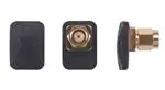
2.4GHz Button Antenna
Features
:
Tiny Size – 19.8mm*14.3mm*16.4mm
2400MHz to 2500MHz Antenna
Wi-Fi / Bluetooth
60%+ Efficiency
RP SMA(M) Connector
IP67
Omnidirectional
ROHS Compliant
Photo:
SPE-16-8-24/B/WY
Page 1 of 30
�1. Introduction
The WCM.01 2.4GHz antenna is the smallest RP-SMA(M) external antenna in
the market, fitting into spaces no other traditional monopole, dipole or
rubber ducky antenna can go. A unique PIFA design ensures omnidirectional
gain across 2.4GHz to 2.5GHz ensuring constant reception and transmission
to make it a great Wi-Fi antenna for 2.4GHz Wi-Fi and Bluetooth applications.
This antenna features greater than 60% efficiency when connected directly
to the ground plane of the device.
Typical Applications
-
Application Points
-
Routers
-
IoT M2M devices
-
Smart home applications
This antenna comes with a RP SMA(M) to be compatible with most Wi-Fi
applications and routers in the market. The WCM.01 antenna is also IP67
water resistant. The ideal position for the antenna to radiate is mounted clear
of metal. Connector is customizable.
Contact Taoglas regional sales office for more information.
SPE-16-8-24/B/WY
Page 2 of 30
�2. Specification
ELECTRICAL
Frequency (MHz)
2400
2450
2500
33.30
30.36
29.65
Ground plane(center)
63.43
71.44
66.85
Ground plane(edge)
Ground plane(center)
Ground plane(edge)
Ground plane(center)
Ground plane(edge)
Average gain (dBi)
55.85
64.20
62.55
58.31
62.11
68.43
71.40
81.30
70.49
73.46
61.73
63.97
69.73
60.87
61.90
-4.78
-5.18
-5.28
Ground plane(center)
-1.98
-1.46
-1.75
Ground plane(edge)
-2.53
-1.65
-2.10
Ground plane(center)
-1.92
-1.46
-1.94
Ground plane(edge)
-2.04
-0.90
-1.57
Ground plane(center)
-2.34
-1.52
-2.16
Ground plane(edge)
-2.07
-1.34
-2.08
0.89
0.40
0.12
Efficiency (%)
In free space
On the 10*10cm
On the 20*20cm
On the 30*30cm
In free space
On the 10*10cm
On the 20*20cm
On the 30*30cm
Peak gain (dBi)
In free space
On the 10*10cm
Ground plane(center)
2.02
2.45
2.37
On the 10*10cm
Ground plane(edge)
3.46
4.09
3.47
On the 20*20cm
Ground plane(center)
4.26
4.54
3.69
On the 20*20cm
Ground plane(edge)
4.02
5.40
4.65
On the 30*30cm
Ground plane(center)
3.64
4.85
4.06
On the 30*30cm
Ground plane(edge)
3.79
4.23
3.15
Radiation
Omnidirectional
Polarization
Linear
Impedance
50 Ω
Input Power
10W
MECHANICAL
Antenna Dimension
19.8*14.3*16.4mm
Casing
ABS
Connector
RP-SMA(M)
Weight
6g
Ingress Protection Rating
IP67
SPE-16-8-24/B/WY
Page 3 of 30
�ENVIRONMENTAL
Operation Temperature
-40°C ~ + 85°C
Storage Temperature
-40°C ~ + 85°C
Humidity
Non-condensing 65°C 95% RH
SPE-16-8-24/B/WY
Page 4 of 30
�3. Antenna Characteristics
3.1 Testing Setup
a) In free space
b) With 10*10cm
c) With 10*10cm
ground plane center
ground plane edge
d) With 20*20cm
e) With 20*20cm
f) With 30*30cm
g) With 30*30cm
ground plane center
ground plane edge
ground plane center
ground plane edge
Figure.1 Antenna Measurement Setup
SPE-16-8-24/B/WY
Page 5 of 30
�3.2 Return Loss (In free space)
Figure 2. Return loss of WCM.01 antenna
3.3 Return Loss(On the ground plane Center)
Figure 3. Return loss of WCM.01 antenna with different ground plane size
SPE-16-8-24/B/WY
Page 6 of 30
�3.4 Return Loss (On the ground plane Edge)
Figure 4. Return loss of WCM.01 antenna with different ground plane size
3.5 Efficiency (In free space)
Figure 5. Efficiency of WCM.01 antenna
SPE-16-8-24/B/WY
Page 7 of 30
�3.6 Efficiency (On the ground plane Center)
Figure 6. Return loss of WCM.01 antenna with different ground plane size
3.7 Efficiency (On the ground plane Edge)
Figure 7. Return loss of WCM.01 antenna with different ground plane size
SPE-16-8-24/B/WY
Page 8 of 30
�3.8 Peak Gain (In free space)
Figure 8. Peak gain of WCM.01 antenna with different ground plane size
3.9 Peak Gain (On the ground plane Center)
Figure 9. Peak gain of WCM.01 antenna with different ground plane size
SPE-16-8-24/B/WY
Page 9 of 30
�3.10 Peak Gain (On the ground plane Edge)
Figure 10. Peak gain of WCM.01 antenna with different ground plane size
3.11 Average Gain (In free space)
Figure 11. Average gain of WCM.01
SPE-16-8-24/B/WY
Page 10 of 30
�3.12 Average Gain (On the ground plane Center)
Figure 12. Average gain of WCM.01 antenna with different ground plane size
3.13 Average Gain (On the ground plane Edge)
Figure 13. Average gain of WCM.01 antenna with different ground plane size
SPE-16-8-24/B/WY
Page 11 of 30
�4. Antenna Radiation Patterns
The antenna radiation patterns were measured in CTIA certified ETS Anechoic
Chamber. The measurement setup as below,
Y
X
Z
In Free Space
Y
Y
X
X
Z
Z
On 10*10cm ground plane (Center)
On 10*10cm ground plane (Edge)
SPE-16-8-24/B/WY
Page 12 of 30
�Y
Y
X
X
Z
Z
On 20*20cm ground plane (Center)
Y
On 20*20cm ground plane (Edge)
Y
X
Z
On 30*30cm ground plane (Center)
X
Z
On 30*30cm ground plane (Edge)
Figure.14. Testing Setup in ETS Anechoic Chamber
SPE-16-8-24/B/WY
Page 13 of 30
�4.1 2D Radiation Pattern (In free space)
XY Plane
X
Y
XZ Plane
YZ Plane
Z
Z
Y
X
SPE-16-8-24/B/WY
Page 14 of 30
�4.2 3D Radiation Pattern (In free space)
2400MHz
2450MHz
2500MHz
SPE-16-8-24/B/WY
Page 15 of 30
�4.3 2D Radiation Pattern (On the 10*10cm ground plane Center)
XY Plane
X
Y
XZ Plane
YZ Plane
Z
Z
Y
X
SPE-16-8-24/B/WY
Page 16 of 30
�4.4 3D Radiation Pattern (On the 10*10cm ground plane Center)
2400MHz
2450MHz
2500MHz
SPE-16-8-24/B/WY
Page 17 of 30
�4.5 2D Radiation Pattern (On the 10*10cm ground plane Edge)
XY Plane
X
Y
XZ Plane
YZ Plane
Z
Z
Y
X
SPE-16-8-24/B/WY
Page 18 of 30
�4.6 3D Radiation Pattern (On the 10*10cm ground plane Edge)
2400MHz
2450MHz
2500MHz
SPE-16-8-24/B/WY
Page 19 of 30
�4.7 2D Radiation Pattern (On the 20*20cm ground plane Center)
XY Plane
X
Y
XZ Plane
YZ Plane
Z
Z
Y
X
SPE-16-8-24/B/WY
Page 20 of 30
�4.8 3D Radiation Pattern (On the 20*20cm ground plane Center)
2400MHz
2450MHz
2500MHz
SPE-16-8-24/B/WY
Page 21 of 30
�4.9 2D Radiation Pattern (On the 20*20cm ground plane Edge)
XY Plane
X
Y
XZ Plane
YZ Plane
Z
Z
X
Y
SPE-16-8-24/B/WY
Page 22 of 30
�4.10 3D Radiation Pattern (On the 20*20cm ground plane Edge)
2400MHz
2450MHz
2500MHz
SPE-16-8-24/B/WY
Page 23 of 30
�4.11 2D Radiation Pattern (On the 30*30cm ground plane Center)
XY Plane
X
Y
XZ Plane
YZ Plane
Z
Z
Y
X
SPE-16-8-24/B/WY
Page 24 of 30
�4.12 3D Radiation Pattern (On the 30*30cm ground plane Center)
2400MHz
2450MHz
2500MHz
SPE-16-8-24/B/WY
Page 25 of 30
�4.13 2D Radiation Pattern (On the 30*30cm ground plane Edge)
XY Plane
X
Y
XZ Plane
YZ Plane
Z
Z
Y
X
SPE-16-8-24/B/WY
Page 26 of 30
�4.14 3D Radiation Pattern (On the 30*30cm ground plane Edge)
2400MHz
2450MHz
2500MHz
SPE-16-8-24/B/WY
Page 27 of 30
�5. Drawing(Unit: mm)
SPE-16-8-24/B/WY
Page 28 of 30
�6. Packaging
SPE-16-8-24/B/WY
Page 29 of 30
�Taoglas makes no warranties based on the accuracy or completeness of the contents of this document
and reserves the right to make changes to specifications and product descriptions at any time without
notice. Taoglas reserves all rights to this document and the information contained herein.
Reproduction, use or disclosure to third parties without express permission is strictly prohibited.
Copyright © Taoglas Ltd.
SPE-16-8-24/B/WY
Page 30 of 30
�
很抱歉,暂时无法提供与“WCM.01.0151”相匹配的价格&库存,您可以联系我们找货
免费人工找货