nRF24AP2
nRF24AP2-USB
Single-chip ANTTM ultra-low power
wireless network solution
Product Specification v1.0
Key Features
•
•
•
•
•
•
•
•
•
•
•
•
•
•
•
•
•
•
Second generation single chip ANT solution
Bridge from ANT networks and devices to
computers, Macs, and the internet
nRF24AP2- USB supports up to eight ANT
(logic) channels – ideal for hubs
World wide 2.4 GHz ISM band operation
USB v2.0 interface
Fully embedded, enhanced ANT protocol stack
Built-in device search and pairing
Built-in timing and power management
Built-in interference handling
Configurable channel period 5.2 ms - 2 s
Broadcast, Acknowledged and Burst
communication modes
Burst data rate up to 20 kbps
Simple to complex network topologies:
Peer-to-peer, star, tree and practical mesh
Supports public, private and managed networks
Support for ANT+ device profile
implementations enabling multivendor
interoperability
Fully interoperable with nRF24AP1,
Dynastream ANT chipset / module based products and other nRF24AP2 variants
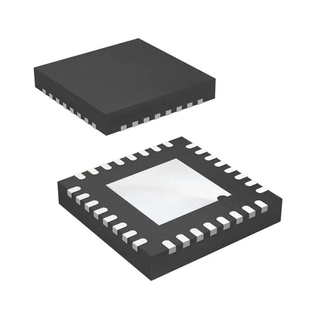
RoHS compliant 5x5 mm 32-pin QFN package
Low cost external 16 MHz crystal
Applications
•
•
•
•
•
•
•
•
Sports
Wellness
Home health monitoring
Home/industrial automation
Environmental sensor networks
Active RFID
Logistics/goods tracking
Audience-response systems
All rights reserved. ANTTM is a trademark of Dynastream Innovation Inc.
Reproduction in whole or in part is prohibited without the prior written permission of the copyright holder.
April 2010
�nRF24AP2-USB Product Specification
Liability disclaimer
Nordic Semiconductor ASA reserves the right to make changes without further notice to the product to
improve reliability, function or design. Nordic Semiconductor ASA does not assume any liability arising out
of the application or use of any product or circuits described herein.
All application information is advisory and does not form part of the specification.
Limiting values
Stress above one or more of the limiting values may cause permanent damage to the device. These are
stress ratings only and operation of the device at these or at any other conditions above those given in the
specifications are not implied. Exposure to limiting values for extended periods may affect device reliability.
Life support applications
Nordic Semiconductor’s products are not designed for use in life support appliances, devices, or systems
where malfunction of these products can reasonably be expected to result in personal injury. Nordic Semiconductor ASA customers using or selling these products for use in such applications do so at their own
risk and agree to fully indemnify Nordic Semiconductor ASA for any damages resulting from such improper
use or sale.
Datasheet status
This product specification contains target specifications for Nordic
Semiconductor’s product development.
Preliminary product specification This product specification contains preliminary data; supplementary
data may be published from Nordic Semiconductor ASA later.
Product specification
This product specification contains final product specifications. Nordic
Semiconductor ASA reserves the right to make changes at any time
without notice in order to improve design and supply the best possible
product.
Objective product specification
Contact details
For your nearest dealer, please see www.nordicsemi.com.
Main office:
Otto Nielsens veg 12
7004 Trondheim
Phone: +47 72 89 89 00
Fax: +47 72 89 89 89
www.nordicsemi.com
Revision 1.0
Page 2 of 44
�nRF24AP2-USB Product Specification
RoHS statement
This product meets the requirements of Directive 2002/95/EC of the European Parliament and of the
Council on the Restriction of Hazardous Substances (RoHS). Complete hazardous substance reports as
well as material composition reports for all active Nordic products can be found on our web site
www.nordicsemi.com.
Revision History
Date
April 2010
Revision 1.0
Version
1.0
Description
Product Specification
Page 3 of 44
�nRF24AP2-USB Product Specification
Contents
1
1.1
1.2
2
2.1
2.2
2.3
2.4
2.4.1
2.4.2
3
3.1
3.2
4
4.1
4.2
4.2.1
4.2.2
4.2.3
4.2.4
4.2.5
4.2.6
4.2.7
5
5.1
5.2
5.3
5.3.1
5.3.2
5.3.3
5.3.4
5.3.5
5.3.6
5.3.7
6
6.1
6.2
6.3
6.3.1
6.3.2
7
8
8.1
8.2
Introduction ...............................................................................................
Prerequisites ........................................................................................
Writing conventions ..............................................................................
Product overview ......................................................................................
Features ...............................................................................................
Block diagram ......................................................................................
Pin Assignments ..................................................................................
Pin Functions .......................................................................................
Power supply pins ...........................................................................
Reset pin .........................................................................................
RF transceiver ...........................................................................................
Features ...............................................................................................
Block diagram ......................................................................................
ANT overview ............................................................................................
Block diagram ......................................................................................
Functional description ..........................................................................
ANT nodes.......................................................................................
ANT channels ..................................................................................
ANT channel configuration ..............................................................
Proximity search ..............................................................................
Continuous scanning mode .............................................................
ANT network topologies ..................................................................
ANT message protocol ....................................................................
Host interface ............................................................................................
Features ...............................................................................................
Block diagram ......................................................................................
Functional description ..........................................................................
Physical USB connection ................................................................
USB enumeration ............................................................................
USB descriptors...............................................................................
String descriptors.............................................................................
Customize descriptors .....................................................................
Control transfer ................................................................................
Host Command flow .......................................................................
On-chip oscillator......................................................................................
Features ...............................................................................................
Block diagram ......................................................................................
Functional description ..........................................................................
16 MHz crystal oscillator..................................................................
External 16 MHz clock .....................................................................
Operating conditions ................................................................................
Electrical specifications ...........................................................................
USB interface .......................................................................................
DC Electrical characteristics ...............................................................
Revision 1.0
Page 4 of 44
6
6
6
7
8
9
10
10
11
11
12
12
12
13
13
13
14
14
15
17
18
18
19
21
21
21
21
22
22
22
25
25
26
28
30
30
30
30
30
31
32
33
34
35
�nRF24AP2-USB Product Specification
8.3
Current consumption ............................................................................
9
Absolute maximum ratings ......................................................................
10
Mechanical specification..........................................................................
11
Reference circuitry....................................................................................
11.1
PCB guidelines.....................................................................................
11.2
Schematics...........................................................................................
11.3
Layout ..................................................................................................
11.4
Bill Of Materials (BOM) ........................................................................
12
Ordering information ................................................................................
12.1
Package marking .................................................................................
12.1.1
Abbreviations ...................................................................................
12.2
Product options ....................................................................................
12.2.1
RF silicon .........................................................................................
12.2.2
Development tools ...........................................................................
13
Glossary.....................................................................................................
Revision 1.0
Page 5 of 44
36
37
38
39
39
40
41
42
43
43
43
43
43
43
44
�nRF24AP2-USB Product Specification
1
Introduction
The nRF24AP2 components belong to Nordic Semiconductor’s low-cost, high-performance family of 2.4
GHz ISM Connectivity-on-Chip devices with the ANT protocol stack embedded. nRF24AP2 offers the
market’s most efficient, single chip, transceiver solution for Ultra Low Power (ULP) networks, through the
integration of the extremely power efficient ANT protocol stack, the world leading Nordic Semiconductor
2.4 GHz RF technology as well as critical low-power oscillator and timing features.
This document covers the product nRF24AP2-USB, which is a single-chip implementation of an ANT USB
bridge.
1.1
Prerequisites
In order to fully understand the product specification, a good knowledge of electronics and software
engineering is necessary. Please also refer to the document ANT Message Protocol and Usage when
reading this product specification. You can download the document from Nordic’s web site
www.nordicsemi.com or from www.thisisant.com.
1.2
Writing conventions
This product specification follows a set of typographic rules to ensure that the document is consistent and
easy to read. The following writing conventions are used:
•
Commands, bit state conditions, and register names are written in Courier New.
•
Pin names and pin signal conditions are written in Courier New bold.
•
Cross references are underlined and highlighted in blue.
Revision 1.0
Page 6 of 44
�nRF24AP2-USB Product Specification
2
Product overview
ANT is a demonstrably superior Wireless Sensor Network (WSN) RF protocol for almost all practical ultralow power networking applications – from simple point-to-point links to complex networks. Embedded in
nRF24AP2 devices, it is paired up with Nordic Semiconductor's market leading 2.4 GHz radio technology.
The combination gives you a high performance-, ultra-low-power network connectivity to applications.
The nRF24AP2-USB, with its USB v2.0 compatible serial interface, is made specifically to act as a bridge
between an ANT wireless network and backbone infrastructure. Backbone infrastructure can be advanced
user interfaces, storage on a computer or other USB enabled equipment.
Figure 1. on page 7 shows a network in which a network node with nRF24AP2-USB embedded, communicates with up to eight ANT nodes. An example might be a computer collecting data from a hub (a watch) in
a portable ANT sensor network containing several sensors (like heart rate-, speed and distance sensors).
The 8-channel nRF24AP2-USB node can of course also set up ANT channels with other nodes (gym
equipment, for instance). The information collected though nRF24AP2-USB can then be used either locally
or shared with others over local networks or internet.
Internet
Computer with
nRF24AP2-USB
stick
N
LA
W
.
.
.
.
.
.
node
2
node
8
Figure 1. Simple setup with nRF24AP2-USB
See Figure 10. on page 19 for more complex ANT-network topologies.
Revision 1.0
Page 7 of 44
�nRF24AP2-USB Product Specification
2.1
Features
Features of the nRF24AP2-USB include:
•
•
•
•
Ultra low power 2.4 GHz transceiver
X World wide 2.4 GHz ISM band
operation
X Based on nRF24L01+ transceiver
X GFSK modulation
X 1 Mbps on-air data rate
X 1 MHz frequency resolution
X 78 RF channels
X -85 dBm sensitivity
X Up to 0 dBm output power
ANT protocol stack
X Full implementation of the physical,
data link, network- and transport
OSI layers
X Packet-based communication – 8 byte
payload per packet
X Optimized for ultra-low power
operation
ANT channels
X Logic communication channel
between ANT nodes
X nRF24AP2USB support up to 8
channels–ideal for hubs
X Built-in timing and power management
X Built-in interference handling
X Configurable channel period
5.2 ms - 2 s
X Broadcast, acknowledged and burst
communication modes
X Burst data rate up to 20 kbps
Device search and pairing
X Wild-card searches
X Proximity searches
X Specific searches
X Automatic link establishment if
correct device is found
X Automatic re-link attempt if link is lost
X Configurable search timeout
Revision 1.0
•
•
•
•
•
•
Network topologies
X Point-to- point and star networks using
independent ANT channels
X Shared networks: Polled data collection
(N:1) by using ANT shared channel
option
X Broadcast networks: Mass distribution
of data (1:N)
Network management / ANT+
X Supports public and private (managed)
networks
X Support for ANT+
system implementations enabling multivendor interoperability
ANT core stack enhancements
X Background scanning channel
X Continuous scanning mode
X High density node support
X Improved channel search
X Channel ID management
X Improved transmission power control
on a per channel basis
X Frequency agility
X Proximity search
Power Management
X Fully controlled by ANT protocol stack
X On-chip voltage regulator
X USB supply operation
X 4.0 to 5.25V supply range
On-chip oscillators and clock inputs
X 16 MHz crystal oscillator supporting lowcost crystals
Host interface
X USB v2.0 compatible
X On-chip pull-up resistor on D+
X Two control endpoints and two bulk
endpoints
X Suspend and resume power
management functions
X USB drivers and ANT command
libraries supported by ANT
Page 8 of 44
�nRF24AP2-USB Product Specification
2.2
Block diagram
nRF24AP2 is composed of five main blocks as shown in Figure 2. The blocks indicate the interface, power
management, the ANT protocol engine, on-chip oscillators and the RF transceiver.
nRF24AP2
Computer
ANT1
USB
Ultra low power
2.4 GHz
transceiver
ANT2
VDD_PA
ANT protocol
engine
VDD
DEC1
DEC2
Iref
Power
management
16 MHz
On-chip
oscillators
VSS
Figure 2. Block diagram of nRF24AP2 solution
To find more information about each block in the diagram, see Table 1.
Name
RF transceiver
ANT protocol engine
USB interfaces
On-chip oscillators
Power management
Reference
Chapter 3 on page 12
Chapter 4 on page 13
Chapter 5 on page 21
Chapter 6 on page 30
Chapter 8 on page 33
Table 1. Block diagram cross references
Revision 1.0
Page 9 of 44
�nRF24AP2-USB Product Specification
XC2
VSS
DEC2
DEC1
VDD
VSS
IREF
Pin Assignments
XC1
32
31
30
29
28
27
26
25
VDD
1
24
VDD
VBUS
2
23
VSS
VDD
3
22
ANT2
D+
4
21
ANT1
D-
5
20
VDD_PA
VSS
6
19
VDD
VSS
7
18
VSS
RESET
8
17
VSS
nRF24AP2-USB
QFN32 5X5
13
14
15
16
NC
NC
12
NC
11
NC
10
VSS
VDD
9
NC
Exposed die pad
NC
2.3
Figure 3. nRF24AP2-USB pin assignment (top view) for a QFN32 5x5 mm package
2.4
Pin Functions
Pin
21, 22
5, 4
28, 29
25
Name
ANT1, ANT2
D-, D+
DEC1, DEC2
IREF
Type
RF
Digital I/O
Power
Analog Input
10, 11, 13, 14,
15, 16
8
NC
NC
2
1, 3, 9,
19, 24, 27
20
6, 7, 12, 17,
18, 23, 26, 30
32, 31
RESET
VBUS
VDD
VDD_PA
VSS
XC1, XC2
Exposed die
pad
Description
Differential antenna connection (TX and RX)
Differential USB connection
Power supply outputs for de-coupling purposes
Device reference current output. To be connected
to reference resistor on PCB
Not connected
Digital Input Reset, active low. Connect to VDD if not used
Power
Power
USB power supply
Alternative power supply pins. The VDD pins must
always be connected and de-coupled externally.
Power Output Power supply output (+1.8V) for on-chip RF Power
amplifier
Power
Ground (0V)
Analog Input Connection for 16 MHz crystal
Power/heat
Not connected
relief
Table 2. nRF24AP2-USB pin functions
Revision 1.0
Page 10 of 44
�nRF24AP2-USB Product Specification
2.4.1
Power supply pins
VBUS and VSS are the power supply and ground pins. The nRF24AP2-USB can operate from a single
power supply.
The nRF24AP2-USB contains an on-chip regulator that produces +3.3V on the VDD pins, from the VBUS
supply line (4.0 – 5.25V). Alternatively, the VBUS pin can be left open and the VDD pins may be fed from an
external 3.3V supply. In this case, the on-chip 3.3V regulator is switched off.
2.4.2
Reset pin
The RESET pin provides an optional reset when the nRF24AP2-USB is placed in a system that has a
master reset source, this pin is not needed for normal application. Pull RESET pin low for minimum 0.2 μs
and return to high, this will reset the nRF24AP2-USB to the default state. Connect RESET pin to VDD if not
used in the application.
Revision 1.0
Page 11 of 44
�nRF24AP2-USB Product Specification
3
RF transceiver
All transceiver operations are controlled solely by the ANT protocol stack. Configuration of the ANT protocol stack occurs through a serial interface by issuing ANT commands to nRF24AP2-USB.
3.1
Features
Features of the RF transceiver include:
•
•
•
•
3.2
General
X Worldwide 2.4 GHz ISM band operation
X Common antenna interface in transmit and receive
X GFSK modulation
X 1 Mbps on air data rate
Transmitter
X Programmable output power: 0, -6, -12 or -18 dBm
Receiver
X Integrated channel filters
X -85 dBm sensitivity
RF Synthesizer
X Fully integrated synthesizer
X 1 MHz frequency programming resolution
X 78 RF channels in the 2.4 GHz ISM band
X Accepts low cost ± 50 ppm 16 MHz crystal
X 1 MHz non-overlapping channel spacing
Block diagram
Figure 4. on page 12 shows a block diagram of the RF transceiver in nRF24AP2-USB.
RF transmitter
PA
TX
filter
GFSK
modulator
RF receiver
ANT protocol stack
ANT1
LNA
RX
filter
GFSK
demodulator
ANT2
RF synthesizer
Figure 4. Internal circuitry of RF transceiver relative to ANT
Revision 1.0
Page 12 of 44
�nRF24AP2-USB Product Specification
4
ANT overview
The ANT protocol has been engineered for simplicity and efficiency. In operation, this results in ultra-low
power consumption, maximized battery life, a minimal burden on system resources, simpler network
designs and lower implementation costs.
4.1
Block diagram
Application/Presentation layers
User defined
Higher level security
Network/Transport & low level security
Implemented by ANT
Data link layer
Physical layer
Figure 5. OSI layer model of ANT protocol stack
ANT provides carefree handling of the Physical, Data Link, Network, and Transport OSI layers. Please
see Figure 5. on page 13. In addition, it incorporates key, low-level security features that form the foundation for user-defined, sophisticated, network-security implementations. ANT ensures adequate user control
while considerably easing the computational burden, by providing a simple yet effective wireless networking solution.
4.2
Functional description
A brief overview of the ANT concept is presented here for convenience. A complete description of the ANT
protocol is found in the document ANT Message Protocol and Usage available at www.nordicsemi.com or
www.thisisant.com.
Revision 1.0
Page 13 of 44
�nRF24AP2-USB Product Specification
4.2.1
ANT nodes
All ANT networks are built up of nodes. See the ANT node represented in Figure 6. on page 14. A node
can be anything from a simple sensor to a complex, collection unit like a watch or computer. Common to all
nodes is that they contain an ANT engine (nRF24AP2) handling all connectivity to other nodes and a host
processor handling the application features. nRF24AP2 interfaces to the host processor through a serial
interface, and all configuration and control are performed using a simple command library.
Node
Serial interface
Host MCU
nRF24AP2
(ANT engine)
Figure 6. The ANT node
4.2.2
ANT channels
nRF24AP2 can establish one or up to eight logic channels, called ANT channels, to other ANT nodes. The
number of ANT channels available depends on the nRF24AP2 variant being used.
Node 1
Node 2
Host MCU
Host MCU
Channel A
nRF24AP2
(ANT engine)
nRF24AP2
(ANT engine)
Master
Slave
Figure 7. ANT nodes and the channel between them
The simplest ANT channel is called an independent channel and consists of two nodes, one acting as
master, the other as slave for this channel. For each ANT channel opened, nRF24AP2 will set up and
manage a synchronous wireless link, exchanging data packets with other ANT nodes at preset time
intervals called channel periods. See Figure 8. on page 15. The master controls the timing of a channel,
that is to say, it will always initiate communication between the nodes. The slave locks on to the timing set
by the master, receives the transmissions from the master and can then (if configured so) send acknowledge and/or data (if any) back to the master.
Revision 1.0
Page 14 of 44
�nRF24AP2-USB Product Specification
Tch
Tch
Tch
Master
time
Slave
time
Channel time slot
(Always)
Forward
direction
(Optional)
Reverse
direction
Figure 8. Channel communication showing forward and reverse directions. Not to scale
At each time slot an ANT channel can transfer user data (8 bytes) both ways as simple broadcasts,
broadcast with acknowledgement from the receiver, or transfer data as bursts (this will extend the time slot
used) to accommodate transfer of larger blocks of user data. The total available payload bandwidth (20
kbps) in an ANT node is shared between active ANT channels through a Time Division Multiple Access
(TDMA) scheme. If a channel time slot comes up, but there is no new data from the master, the master will
still send the last packet to keep the timing of the channel and enable the slave to send data back if
needed.
Each ANT channel available in the nRF24AP2 can for example be configured as a simple unidirectional
(broadcast), or bi-directional independent channel; or as a more complex, shared channel where a master
interfaces to multiple slaves (1:N topologies). Please see the ANT Message Protocol and Usage document
for further details on shared ANT channels.
4.2.3
ANT channel configuration
Unique to ANT is that the setup of each ANT channel is independent from all the other ANT channels in the
network, including other channels in the same node. This means that one ANT node can act as master on
one ANT channel while being a slave to another. Since there is no overall ‘network master’ present in ANT
networks, ANT allows you to configure and run each ANT channel solely based on the needs of the nodes
on that channel. Search- and pairing algorithms in ANT let you easily set up and shut down ANT channels
in an ad-hoc fashion. This gives you ultimate flexibility in adjusting ANT channel parameters like data rate
and latency versus power consumption. Moreover, you only make the network as complex as it needs to
be at any given time. In order for two ANT nodes to set up an ANT channel, they must share a common
channel configuration and channel ID. The necessary configuration parameters are summarized in Table
3. on page 16.
Revision 1.0
Page 15 of 44
�nRF24AP2-USB Product Specification
Parameter
Channel period
RF frequencies
Channel type
Network type
Transmission type
Device type
Device number
Comment
Channel configuration
Time interval between data exchanges on this
channel (5.2 ms - 2 s)
Which of the 78 available RF frequencies is used
by this channel
Bi-directional slave, bi-directional master, shared
bi-directional slave, Slave Receive only
Decides if this ANT channel is going to be generally accessible (public) to all ANT nodes, or if it
shall limit its connectivity to devices belonging to a
managed or private network
Channel ID
1 byte – Identifying characteristics of the transmission, can for instance contain codes on how payload is to be interpreted
1 byte - ID to identify the device type of the channel master (Ex: heartrate belt, temperature sensor
etc.)
2 byte - Unique ID for this channel
Table 3. ANT channel ID
The channel configuration parameters are static system parameters that must match in the master and
slave, and the channel ID is included in all transmissions identifying the two nodes for each other. For indepth details on each parameter please refer to ANT Message Protocol and Usage.
Network
In addition to setting the content of the channel ID, which is the primary ID of an ANT node, ANT nodes
can limit their connectivity to a selection of other ANT nodes by defining a network for each ANT channel.
The limited access to certain networks is managed through unique network keys
The defined ANT networks are:
1.
2.
3.
Public networks: These are open ANT networks with no limitation on connectivity. All ANT
nodes sharing the same channel configuration (by design or by accident) will be able to connect.
This is the default setting in nRF24AP2.
Managed networks: These are ANT networks managed by special interest groups or alliances.
An example is the ANT+ alliance for sport and wellness products. To join the ANT+ alliance,
please visit www.thisisant.com. By joining the ANT+ alliance and complying with the ANT+
device profiles set by the alliance, you achieve two goals:
X Limited connectivity: Only other ANT+ compliant devices can connect on this channel.
X Interoperability: Your node can connect to ANT+ compliant products from other vendors.
Private networks: Your own protected networks, and no other devices, will be able to connect to
your ANT nodes unless you share the network key with someone outside the network. Please
note that this requires purchase of a unique network key from ANT, see www.thisisant.com.
Since the network parameter can be chosen independently for each ANT channel, one ANT node can
have up to eight ANT channels, operating on different networks at the same time.
Note: The network parameter has no impact on the network topologies you can build. It is merely a
tool to protect your ANT network and prevent accidental or deliberate access from other ANT
nodes.
Revision 1.0
Page 16 of 44
�nRF24AP2-USB Product Specification
Channel ID, search and pairing
The primary parameters which two ANT nodes use to identify each other make up the channel ID. Once
an ANT channel is established, the channel ID parameters must of course match; but they don’t have to
be known by both nodes (pre-configured) to be able to establish an ANT channel.
When an nRF24AP2 configured as a master (set in channel type) opens an ANT channel, it will broadcast
its entire channel ID. Hence you must configure all three channel ID parameters before opening an ANT
channel as a master.
On the other hand, in a slave you can configure nRF24AP2 to search for and connect with both known and
unknown masters. To connect with a known master you must configure the Transmission type, Device
type and Device number in nRF24AP2 before opening the ANT channel.
You can also configure the nRF24AP2 to conduct wild-card searches on one or more of the three parameters in the channel ID to enable it to pair up with unknown masters. You can for instance set only the
Device type of the masters you want to link up with, and set wild cards on the Transmission type and
Device number. If a new master with a matching Device type is found, the slave device will connect and
store the unknown parts of the channel ID. The new parts of the channel ID can then be stored in the host
MCU to enable specific searches for this master later.
4.2.4
Proximity search
When using the basic search and pairing algorithm a slave will automatically identify and connect to the
first master it finds matching the search criteria. In areas where you either have a high density of similar
master nodes or high density of independent ANT networks, there is always the chance that multiple masters are found within the coverage area. This presents the risk that it is not the master you want to connect
to that is found first. The proximity search feature in ANT designates ‘bins’ of proximity from 1 (closest) to
10 (furthest) as shown in Figure 9. on page 17.
Figure 9. Standard search (a), Proximity search (b), showing bins 1-5 (of maximum 10)
This ‘binning’ enables you to further control your search, for example by only accepting the master that is
closest (only accepting masters that fall in bin 1-2). This makes it easy for a user to pair up network nodes
and prevent accidental connection to nodes possibly belonging to another network close by.
Revision 1.0
Page 17 of 44
�nRF24AP2-USB Product Specification
4.2.5
Continuous scanning mode
Continuous scanning mode allows for fully asynchronous communication between an ANT node using
continuous scanning mode, and any other ANT node using a standard master channel. This has two main
advantages over only using standard ANT channels. The first is that the latency to initiate communication
with the scanning node is reduced to zero and every message sent by a master channel in proximity will be
received by the scanning device. Secondly, the requirement to maintain communication for the purpose of
synchronization while in proximity is removed. This means that it is possible for nodes to come and go very
quickly or to turn off for long periods of time in between communication events. This saves power on the
transmitting node.
The disadvantage of continuous scanning mode is that it consumes much more power than standard ANT
channels. Therefore, continuous scanning mode will typically be used only on devices that are plugged in
and not mobile such as a computer (USB dongle). Another disadvantage is that a node in scanning mode
can no longer be configured to have discoverable master channels because scanning mode disables standard ANT channel functionality. It is worth noting that two ANT nodes in scanning mode cannot communicate with one another because neither will be able to spontaneously generate communication.
Standard ANT channels are recommended over scanning channels, even in dynamic systems where
devices are coming and going. This is because scanning channels are not recommended for a mobile
network, which is the primary use case for ANT. Scanning channels will typically be used in statically
located networks where the scanning channel node is plugged in and not mobile.
4.2.6
ANT network topologies
By combining ANT channels with different features depending on local needs, you can build anything from
very simple peer-to-peer links and star networks to complex networks as shown in Figure 10. on page 19.
Revision 1.0
Page 18 of 44
�nRF24AP2-USB Product Specification
ANT-FS
(Secure Authenticated)
PEER
TO
PEER
BROADCAST
STAR
Acknowledged
Broadcast
Bidirectional
M
14
M
M
1
12
1
12
1
12
2
11
2
11
2
11
3
10
3
10
3
10
4
9
4
9
4
9
5
8
5
8
6
7
6
7
SHARED
BI-DIRECTIONAL
n
16
1
12
2
11
3
10
4
8
?
6
7
5
9
8
SHARED
UNI-DIRECTIONAL
15
13
AD-HOC
AUTO
SHARED
7
6
SCANNING MODE
PRACTICAL MESH
Relay
Sensor
SHARED CLUSTER
Hub
Figure 10. Network topology examples supported by ANT
4.2.7
ANT message protocol
The host microcontroller handles all the configuration and control of the various ANT node and channel
parameters in nRF24AP2 over a simple serial interface, by using the command library. See the document
ANT Message Protocol and Usage for further details on the command library.
Revision 1.0
Page 19 of 44
�nRF24AP2-USB Product Specification
Class
Config.
messages
Type
Unassign Channel
Assign Channel
Commands in ANT command library Reply
ANT_UnassignChannel()
Yes
ANT_AssignChannel()
Yes
Channel ID
ANT_SetChannelId()
Yes
Host
ANT_SetChannelPeriod()
ANT_SetChannelSearchTimeout()
ANT_SetChannelRFFreq()
Yes
Yes
Yes
Host
Host
Host
ANT_SetNetworkKey()
ANT_SetTransmitPower()
ANT_AddChannelID()
ANT_ConfigList()
ANT_SetChannelTxPower()
Yes
Yes
Yes
Yes
Yes
Host
Host
Host
Host
Host
ANT_SetLowPriorityChannelSearchTi
meout()
ANT_RxExtMesgsEnable()
ANT_ConfigFrequencyAgility()
ANT_SetProximitySearch()
→ ResponseFunc( -, 0x6F)
ANT_ResetSystem()
ANT_OpenChannel()
ANT_CloseChannel()
ANT_OpenRxScanMode(
ANT_RequestMessage()
ANT_SendBroadcastData()
→ ChannelEventFunc(Chan,EV)
ANT_SendAcknowledgedData()
→ ChannelEventFunc(Chan, EV)
ANT_SendBurstTransferPacket()
→ ChannelEventFunc(Chan, EV)
→ ChannelEventFunc(Chan,
MessageCode) or
→ ResponseFunc(Chan, MsgID)
→ ResponseFunc(Chan, 0x52)
→ ResponseFunc(Chan, 0x51)
→ ResponseFunc(Chan, 0x51)
→ ResponseFunc(-, 0x3E)
ANT InitCWTestMode()
ANT SetCWTestMode()
ANT SendExtBroadcastData()a
→ ChannelEventFunc(Chan, EV)
ANT SendExtAcknowledgedData()a
→ ChannelEventFunc(Chan, EV)
ANT SendExtBurstTransferPacket()a
→ ChannelEventFunc(Chan, EV)
Yes
Host
Yes
Yes
Yes
No
Yes
Yes
Yes
Yes
No
-
Host
Host
Host
ANT
Host
Host
Host
Host
Host
Host/
ANT
Host/
ANT
Host/
ANT
ANT
Yes
Yes
No
ANT
ANT
ANT
ANT
Host
Host
Host
No
Host
No
Host
Channel Period
Search Timeout
Channel RF Frequency
Set Network
Transmit Power
ID List Add
ID List Config
Channel Transmit
Power
Low Priority Search
Timeout
Enable Ext RX Mesgs
Frequency Agility
Proximity Search
Notifications Startup Message
Control
SystemReset
Messages Open Channel
Close Channel
Open Rx Scan Mode
Request Message
Data
Broadcast Data
Messages
Acknowledge Data
Burst Transfer Data
Channel Event Channel Response/
Messages Event
Requested
Response
Messages
Test Mode
Ext Data
messages
Channel Status
Channel ID
ANT Version
Capabilities
CW Init
CW Test
Extended Broadcast
Data
Extended Ack. Data
Extended Burst Data
No
No
From
Host
Host
a. nRF24AP2 does not send these ChannelEventFunctions() to the host. nRF24AP2 will send
extended messages by appending the additional bytes to standard broadcast, acknowledged and
burst data.
Table 4. ANT message summary supported by nRF24AP2
Revision 1.0
Page 20 of 44
�nRF24AP2-USB Product Specification
5
Host interface
The nRF24AP2-USB has a USB v2.0 compliant host interface. This enables direct connection from the
nRF24AP2-USB to a computer or hubs in other USB enabled equipment. Together with the command
libraries and USB drivers available from ANT the nRF24AP2-USB enables ANT connectivity for
applications in computers and other advanced hosts.
5.1
Features
USB serial interface of nRF24AP2-USB:
•
•
•
•
Serial interface engine:
X USB v2.0 compliant
X On-chip pull-up resistor on D+
Two control endpoints and two bulk endpoints
Suspend and resume power management functions
USB drivers and ANT command libraries supported by ANT
The following USB features are necessary to declare when your product undergoes USB compliance
testing:
•
•
•
•
5.2
Full speed peripheral
Microcontroller with USB drivers on same chip
Bus powered
No remote wakeup
Block diagram
Computer
USB Connector
Figure 11. shows a USB block with external signals VBUS, D+,D-,GND, on-chip pull up resistor on D+ on
one side and connection to the RF transceiver on the other.
Resistors
VBUS
D+
D-
nRF24AP2-USB
Matching
network
Antenna
GND
Crystal
Note: The serial resistors on VBUS, D+ and D- are for ESD protection and USB v2.0 compliance
Figure 11. USB block connected to ANT engine
5.3
Functional description
When the nRF24AP2-USB is plugged into a USB the first thing that needs to take place is for the
nRF24AP2-USB to identify itself for the USB hub. This process is called enumeration and is handled automatically by the nRF24AP2-USB. Once the device is enumerated, applications on the host can access the
nRF24AP2-USB using ANT command libraries.
Revision 1.0
Page 21 of 44
�nRF24AP2-USB Product Specification
This section outlines the enumeration process, user configurable USB parameters, and message
exchanges that take place on the nRF24AP2-USB host interface.
5.3.1
Physical USB connection
The physical connection between nRF24AP2-USB and the host must follow the USB standard v2.0 (for
instance, use USB approved connectors) in order for your nRF24AP2-USB based application to go
through USB compliance testing.
5.3.2
USB enumeration
The USB enumeration process is handled by the nRF24AP2-USB. During the enumeration the host reads
out the USB descriptors and strings to determine which device has been connected to the bus. After the
host has received the parameters it will then assign the device an address and allowing it to transfer data
on the bus.
A typical enumeration process consists of the following steps:
1.
2.
3.
4.
5.
6.
7.
8.
The host detects a new device on the bus via the pull up resistor on D+.
The host issues a reset to place the nRF24AP2-USB to the default state. This will enable the
device to respond to the default address zero requests.
The host requests the Device Descriptor on address 0.
The host issues another bus reset.
The host issues a set address command, placing the nRF24AP2-USB in an addressed state.
The host requests the Device Descriptor again.
The host requests the Configuration, Interface and Endpoint Descriptors.
The host requests the String Descriptors.
After the enumeration process the nRF24AP2-USB can transfer ANT messages on the bus. A complete
summary of ANT messages supported are listed in Table 4. on page 20.
5.3.3
USB descriptors
The nRF24AP2-USB has a set of USB descriptors which describe to the host information about manufacturer, product, USB version, the number of endpoints and their types.
Device Descriptor
Configuration Descriptor
Interface Descriptor
Endpoint
Descriptor 1 IN
Endpoint
Descriptor 1 OUT
Figure 12. Organization of USB descriptors
Revision 1.0
Page 22 of 44
�nRF24AP2-USB Product Specification
The device descriptor contains basic information about the device such as the supported USB version,
maximum packet size, vendor and product IDs.
Field
bLength
bDescriptorType
bcdUSB
bDeviceClass
Notes
Value
0x12
0x01
0x0200
0x00
bDeviceSubClass
0x00
bDeviceProtocol
bMaxPacketSize0
idVendor
0x00
0x20
0x0FCF
idProduct
bcdDevice
iManufacturer
iProduct
iSerialNumber
bNumConfigurations
a
a
0x1008
0x0100
0x01
0x02
0x03
0x01
Description
18
DEVICE
2.0
Class defined at interface level
Subclass defined at
interface level
None
32
Dynastream
Innovations, Inc.
0x1008
1.0
1
2
3
1
a. These fields can be customized with your own value
Table 5. Device descriptors
The configuration descriptor specifies how the device is powered, the maximum power consumption, and
the number of interfaces used.
Field
bLength
bDescriptorType
wTotalLength
bNumInterface
bConfigurationValue
iConfiguration
bmAttributes. Reserved
bmAttributes.
RemoteWakeup
bmAttributes. SelfPowered
bmAttributes. Reserved7
bMaxPower
Notes
Value
0x09
0x02
0x0020
0x01
0x01
0x02
0x00
0x0
Description
Valid
CONFIGURATION
32 bytes
1
1
2
Zero
Not supported
0x0
0x1
0x32
No, Bus powered
One
100 mA
Table 6. Configuration descriptor
Revision 1.0
Page 23 of 44
�nRF24AP2-USB Product Specification
The interface descriptor contains information about the number of endpoints and their class.
Field
bLength
bDescriptorType
bInterfaceNumber
bAlternateSetting
bNumEndpoints
bInterfaceClass
bInterfaceSubClass
bInterfaceProtocol
iInterface
Notes
Value
Description
0x09
0x04
Valid
INTERFACE
0
0x00
0x00
0
2
Vendor-specific
Vendor-specific
None
2
0x02
0xFF
0x00
0x00
0x02
Table 7. Interface descriptor
Endpoint descriptors contain information about the transfer type, interval and the packet size. The host will
use the information to decide on the requirements for the bus. The nRF24AP2-USB uses two endpoints for
communication with the host, one configured as IN and the other as OUT.
Field
bLength
bDescriptorType
bEndpointAddress
bmAttributes.
TransferType
bmAttributes. Reserved
wMaxPacketSize
bInterval
Notes
Value
0x07
0x05
0x81
0x2
Description
Valid
ENDPOINT
1 IN
Bulk
0x00
0x0040
0x01
Zero
64 bytes
Ignored for full speed,
Bulk endpoints
Table 8. Endpoint descriptor 1 IN
Field
bLength
bDescriptorType
bEndpointAddress
bmAttributes.
TransferType
bmAttributes. Reserved
wMaxPacketSize
bInterval
Notes
Value
0x07
0x05
0x01
0x2
Description
Valid
ENDPOINT
1 OUT
Bulk
0x00
0x0040
0x01
Zero
64 bytes
Ignored for full speed,
Bulk endpoints
Table 9. Endpoint descriptor 1 OUT
Revision 1.0
Page 24 of 44
�nRF24AP2-USB Product Specification
5.3.4
String descriptors
String descriptors provide information about the manufacturer, product and serial number for the
nRF24AP2-USB. These strings can be modified, see section 5.3.5 on page 25.
String Index 0 returns a list of supported languages.
Field
bLength
bDescriptorType
wLANGID[0]
Notes
Value
0x04
0x03
0x0409
Description
4
STRING
English (US)
Table 10. String index 0 (language identifier)
Field
bLength
bDescriptorType
bString
Notes
a
Value
0x30
0x03
“Dynastream
Innovations”
Description
48
STRING
a. This field can be customized with your own manufacturer string
Table 11. String index 1 (manufacturer string)
Field
bLength
bDescriptorType
bString
Notes
a
Value
Description
0x1E
0x03
STRING
30
"ANT
USBStick2"
a. This field can be customized with your own product string
Table 12. String index 2 (product string)
Field
bLength
bDescriptorType
bString
Notes
a
Value
Description
0x2A
0x03
STRING
42
“123”
a. This field can be customized with your own serial number
Table 13. String index 3 (serial number string)
5.3.5
Customize descriptors
The nRF24AP2-USB is programmed with default VID/PID values which allow it to function with the drivers
and libraries provided by ANT. However, it is possible to customize the nRF24AP2-USB. You can customize the following values and string descriptors:
•
•
•
•
•
Vendor ID (VID)
Product ID (PID)
Manufacturer string
Product string
Serial number
Revision 1.0
Page 25 of 44
�nRF24AP2-USB Product Specification
Use the Set_Descriptor_String(0xC7) command to configure USB descriptor strings. This command is an
extension to the ANT command interface and is sent in the same manner as the other ANT serial commands. The descriptor strings can be set up to three times. See the document ANT Message Protocol and
Usage for further details on the command library.
Note: Do not remove power supply while updating the VID, PID or USB descriptors.
5.3.6
Control transfer
Control transfers are used for all commands and queries during the USB device enumeration process.
The nRF24AP2-USB allows a maximum data packet size of 32 bytes for the control transfers. All control
transfers can have up to three stages, and are handled automatically by the nRF24AP2-USB.
5.3.6.1
Control write transfer
Host
SETUP
DATA0
ACK
nRF24AP2-USB
Figure 13. Setup stage
The setup stage starts with a SETUP token packet, followed by a DATA packet detailing the type of
request. Finally an ACK handshake packet is sent back by the nRF24AP2-USB if the setup data has been
received correctly, otherwise nothing is sent back.
OUT
DATAx
ACK
STALL
(error)
NAK
(not ready)
Figure 14. Data stage (optional)
When the request indicates that the host wants to send control data, the data stage will be made up of one
or more OUT transfers. Each OUT transfer will start with an OUT token packet followed by a DATA packet.
The nRF24AP2-USB will reply with an ACK handshake packet if everything was received correctly. A NAK
will be returned if the previous packet from the host is still being processed. If any part of the token or data
packet was corrupted or missing, nothing will be sent back. A STALL will be returned if the token and data
were received but another error occurred.
Revision 1.0
Page 26 of 44
�nRF24AP2-USB Product Specification
IN
DATA0
(0 Bytes)
ACK
STALL
(error)
NAK
(not ready)
Figure 15. Status stage
The status stage is used to verify the status of the overall request. For a control write transfer the status
stage will start with an IN token packet. The nRF24AP2-USB will reply with a DATA packet of zero length
if the overall request was successful. A STALL will be returned if an error occurred at any point during the
processing of the transfer. A NAK will be returned if the nRF24AP2-USB is still busy processing the transfer. Finally the host will send an ACK handshake packet to indicate that it received the status.
5.3.6.2
Control read transfer
Host
SETUP
DATA0
ACK
nRF24AP2-USB
Figure 16. Setup stage
The setup stage starts with a SETUP token packet, followed by a DATA packet detailing the type of
request. Finally an ACK handshake packet is sent back by the nRF24AP2-USB if the setup data has been
received correctly, otherwise nothing is sent back.
IN
DATAx
ACK
STALL
(error)
NAK
(not ready)
Figure 17. Data stage (optional)
When the request indicates that the host wants to receive control data, the data stage will be made up of
one or more IN transfers. Each IN transfer will start with an IN token packet. The nRF24AP2-USB can
reply with a DATA packet, a STALL indicating an error has occurred or a NAK indicating that the data is not
Revision 1.0
Page 27 of 44
�nRF24AP2-USB Product Specification
yet ready. Finally, when the DATA is received successfully by the host it will send an ACK handshake
packet.
DATA0
(0 Bytes)
OUT
ACK
STALL
(error)
NAK
(not ready)
Figure 18. Status stage
For a control read transfer the status stage is used by the host to acknowledge that it has received the data
successfully. The status stage will start with an OUT token packet followed by a DATA packet of zero
length. The nRF24AP2-USB will reply with an ACK handshake packet if it received the status packets
successfully. A STALL will be returned if an error occurred at any point during the processing of the transfer. A NAK will be returned if the nRF24AP2-USB is busy and requires the host to repeat the status stage.
5.3.7
Host Command flow
All other communication between the host and nRF24AP2 USB will be handled through USB drivers and
libraries available from ANT. These USB libraries interact with the device through two bulk endpoints
(EP1IN and EP1OUT). The use of the host interface is documented in ANT Message Protocol and Usage
which is available as a PDF file from www.nordicsemi.com and www.thisisant.com. The serial messages
detailed in that document are passed between the host and the nRF24AP2-USB inside the data packet
portion of USB bulk transfers.
USB parameters
VID (Vendor Identification)
PID (Product Identification)
IN endpoint address
OUT endpoint address
Value
0x0FCF
0x1008
0x81
0x01
Table 14. Driver/application USB parameters for communication with nRF24 AP2-USB
5.3.7.1
Bulk transfers
Bulk transfers will be used to transport the serial messages specified by the ANT command interface. The
nRF24AP2-USB supports a maximum bulk data packet size of 64 bytes.
Host
IN
DATA
ACK
nRF24AP2-USB
STALL
(error)
NAK
(not ready)
Figure 19. Bulk IN transfer
Revision 1.0
Page 28 of 44
�nRF24AP2-USB Product Specification
When the host is ready to receive bulk data it will send an IN token packet to the IN endpoint (0x81). The
nRF24AP2-USB will either send a DATA packet if one is ready, send a STALL if an error occurred, send a
NAK if it no data is ready yet or do nothing if the IN token was not received properly. Finally the host will
send an ACK handshake packet if it successfully received the DATA packet.
OUT
DATA
ACK
STALL
(error)
NAK
(not ready)
Figure 20. Bulk OUT transfer
When the host wants to send bulk data to the nRF24AP2-USB it will send an OUT token packet to the OUT
endpoint (0x01). This will be followed by a DATA packet containing the bulk data. If the nRF24AP2-USB
received the data successfully it will return an ACK handshaking packet. If an error occurred during processing, the nRF24AP2-USB will return a STALL. If the nRF24AP2-USB is still busy processing the previous DATA packet, a NAK will be returned. If any part of the OUT token or DATA packet was corrupted or
missing the nRF24AP2-USB will do nothing.
5.3.7.2
Bulk transfer example
The libraries available from ANT contain all the supported messages to configure and use the nRF24AP2USB. Figure 21. shows an example of a serial message passing between the host and device.
In this example the host issues an ANT_RequestMessage() in the data packet to read the ANT version of
the device. We have included hexadecimal values to help you should you need to debug the host serial
interface.
Host
OUT
DATA
ACK
nRF24AP2- USB
ANT_RequestMessage(0x3E)
”A4 02 4D 00 3E D5"
Figure 21. Example of OUT transfer (with varying level of detail)
IN
DATA
ACK
ResponseFunc (-, 0x3E)
”A4 0B 3E 41 50 32 55 53 42 31 2E
30 34 00 ED"
Figure 22. Example of IN transfer (with varying level of detail)
Revision 1.0
Page 29 of 44
�nRF24AP2-USB Product Specification
6
On-chip oscillator
In order to provide the necessary clocks for the ANT protocol stack, nRF24AP2 contains one high
frequency oscillator used by the RF transceiver. The high frequency clock source must be a 16 MHz crystal
oscillator.
6.1
•
6.2
Features
Low-power, amplitude regulated 16 MHz crystal oscillator
Block diagram
Amplitude
regulator
XC1
C1
XC2
Crystal
C2
Figure 23. Block diagram of 16 MHz crystal oscillator
6.3
Functional description
6.3.1
16 MHz crystal oscillator
The 16 MHz crystal oscillator is designed to be used with an AT-cut quartz crystal in parallel resonant
mode. To achieve correct oscillation frequency it is very important that the load capacitance matches the
specification in the crystal datasheet. The load capacitance is the total capacitance from the perspective of
the crystal across its terminals:
C LOAD =
C1' ⋅ C 2'
C1' + C 2'
C1' = C1 + C PCB1 + C PIN
C 2' = C 2 + C PCB 2 + C PIN
Revision 1.0
Page 30 of 44
�nRF24AP2-USB Product Specification
C1 and C2 are ceramic SMD capacitors connected between each crystal terminal and VSS. CPCB1 and
CPCB2 are stray capacitances on the PCB. CPIN is the input capacitance on the XC1 and XC2 pins of
nRF24AP2 (typically 1pF). C1 and C2 should be of the same value, or as close as possible.
To ensure a functional radio link the frequency accuracy must be ± 50 ppm or better. The initial tolerance of
the crystal, drift over temperature, aging and frequency pulling due to incorrect load capacitance must all
be taken into account. For reliable operation the crystal load capacitance, shunt capacitance, equivalent
series resistance (ESR) and drive level must comply with the specifications in Table 17. on page 34. It is
recommended to use a crystal with lower than maximum ESR if the load capacitance and/or shunt capacitance is high. This will give faster start-up and lower current consumption.
6.3.2
External 16 MHz clock
nRF24AP2 may be used with an external 16 MHz clock applied to the XC1 pin. The input signal must be
analog, coming from the crystal oscillator of a microcontroller, for example. An input amplitude of 0.8V
peak-to-peak or higher is recommended to achieve low current consumption and a good signal-to-noise
ratio. The DC level is not important as long as the applied signal never rises above VDD or drops below
VSS. The XC1 pin will load the microcontroller’s crystal with approximately 1pF in addition to PCB routing.
XC2 shall not be connected.
Note: A frequency accuracy of ±50 ppm or better is required to get device performance as outlined
in chapter 8 on page 33.
Revision 1.0
Page 31 of 44
�nRF24AP2-USB Product Specification
7
Operating conditions
Symbol
Parameter (condition)
VBUS Supply voltage
VDD Alternative supply voltage
TEMP Operating Temperature
Notes
Min.
4.0
3.05
-40
Typ.
5
3.27
+27
Max. Units
5.25
V
3.5
V
+85
ºC
Table 15. Operating conditions
Symbol
fNOM
fTOL
CL
C0
ESR
PD
Rref
Rrefacc
Parameter (condition)
16 MHz crystal
Nominal frequency (parallel resonant)
Frequency tolerance
Load capacitance
Shunt capacitance
Equivalent series resistance
Drive level
Bias resistor (IREF pin to GND)
Resistance
Tolerance
Notes
Min.
Typ.
Max.
Unit
±50
16
7
100
100
MHz
ppm
pF
pF
Ω
µW
1
kΩ
%
16.000
a
9
3
50
22
a. Includes initial accuracy, stability over temperature, aging and frequency pulling due to incorrect load
capacitance
Table 16. External circuitry specification
Revision 1.0
Page 32 of 44
�nRF24AP2-USB Product Specification
8
Electrical specifications
This section contains electrical and timing specifications.
Conditions: VDD = 3.0V, TA = −40ºC to +85ºC (unless otherwise noted)
Symbol
Parameter (condition)
fOP
PLLres
fXTAL
Δf
RGFSK
Notes
Min.
General RF conditions
a
2400
Operating frequency
PLL Programming resolution
Crystal frequency
Frequency deviation
Air data rate
FCHANNEL Non-overlapping channel spacing
PRF
PRFC
PRFCR
PBW1
PRF1.1
PRF2.1
RXMAX
RXSENS
C/ICO
C/I1ST
C/I2ND
C/I3RD
C/INth
b
c
Transmitter operation
d
Maximum output power
RF power control range
16
RF power accuracy
20dB bandwidth for modulated carrier
Typ.
Max.
2403-2480 2483.5
1
16
±160
1000
1
0
18
950
1st Adjacent Channel Transmit Power 1
+4
20
±4
1100
-20
MHz
-40
2nd Adjacent Channel Transmit Power
2 MHz
Receiver operation
Maximum received signal at < 0.1%
0
BER
Sensitivity (0.1% BER)
-85
RX selectivity according to ETSI EN 300 440-1 V1.3.1 (2001-09) page 27
C/I co-channel
9
st
8
1 ACS, C/I 1 MHz
-20
2nd ACS, C/I 2 MHz
rd
-30
3 ACS, C/I 3 MHz
th
-40
N ACS, C/I f > 6 MHz
i
Units
MHz
MHz
MHz
kHz
kbps
MHz
dBm
dB
dB
kHz
dBc
dBc
dBm
dBm
dBc
dBc
dBc
dBc
dBc
C/INth
-47
dBc
Nth ACS, C/I fi > 25 MHz
RX selectivity with nRF24AP2 equal modulation on interfering signal (Pin = -67dBm for wanted
signal)
C/ICO
C/I co-channel
12
dBc
st
8
dBc
C/I1ST
1 ACS, C/I 1 MHz
nd
C/I2ND
-21
dBc
2 ACS, C/I 2 MHz
-30
dBc
C/I3RD
3rd ACS, C/I 3 MHz
th
C/INth
-40
dBc
N ACS, C/I f > 6 MHz
i
C/INth
-50
Nth ACS, C/I fi > 25 MHz
dBc
th
RX intermodulation performance in line with Bluetooth specification version 2.0, 4
2004, page 42
e
P_IM(3) Input power of IM interferers at 3 and
-36
6 MHz distance from wanted signal
Revision 1.0
Page 33 of 44
November
dBm
�nRF24AP2-USB Product Specification
Symbol
P_IM(4)
P_IM(5)
a.
b.
c.
d.
e.
Parameter (condition)
Input power of IM interferers at 4 and
8 MHz distance from wanted signal
Input power of IM interferers at 5 and
10 MHz distance from wanted signal
Notes
g
Min.
Typ.
-36
g
-36
Max.
Units
dBm
dBm
Usable band is determined by local regulations.
Data rate in each burst on-air.
The minimum channel spacing is 1 MHz.
Antenna load impedance = 15 Ω + j88 Ω.
Wanted signal level at Pin = 64 dBm. Two interferers with equal input power are used. The interferer closest in frequency is unmodulated, the other interferer is modulated equal to the wanted signal. The input
power of interferers where the sensitivity equals BER=0.1% is presented.
Table 17. Transceiver characteristics
8.1
USB interface
The USB interface electrical performance is compliant with the USB specification 2.0.
Characteristic
Symbol
Conditions
Electrical characteristics
Input high voltage (driven)
VIH
Input low voltage
VIL
Differential input sensitivity
VDI
|(D+) – (D-)|
Differential common mode range
VCM
Includes VDI
range
Single ended receiver threshold
VSE
Single ended receiver hysteresis
VSEH
Output low voltage
VOL
Output high voltage
VOH
Differential output signal cross-point
VCRS
voltage
Internal pull-up resistor (Standby
RPU1
mode)
Internal pull-up resistor (Active mode)
RPU2
Termination voltage connected to RPU VTRM
Output driver resistance (does not
ZDRV
Steady state
include the series resistance)
drive
Timing characteristics
Driver rise time
TFR
CL=50pF
Driver fall time
TFF
CL=50pF
Rise/fall time matching
TFRFF
TRF / TFF
Transceiver pad capacitance
CIN
Pad to ground
Min.
Page 34 of 44
Max
2.0
0.8
0.2
0.8
2.5
0.8
2.0
0
2.8
1.3
Unit
V
V
V
V
0.3
3.6
2.0
V
mV
V
V
V
200
900
1100
1575
Ω
1425
3.05
2100
3090
3.5
Ω
V
Ω
20
20
111
20
ns
ns
%
pF
15
4
4
90
Table 18. USB interface characteristics
Revision 1.0
Typ.
�nRF24AP2-USB Product Specification
Symbol
Parameter (condition)
tSuspend Idle to suspend time
tReset Power on reset time, software reset,
and reset pin
tResponse- The time the nRF24AP2-USB uses to
respond to an input command
Max
Notes
Min.
Typ.
Max.
3.25
2.0
Units
ms
ms
1.0
ms
Table 19. Serial timing
8.2
DC Electrical characteristics
Symbol
VDD
IVDD
Parameter (condition)
On-chip voltage regulators
Output voltage
External load current
Notes
Min.
Typ.
Max.
Units
a
3.05
3.27
3.5
2
V
mA
Max.
VDD
0.3·VDD
Units
V
V
a. Also valid for VDD input voltage
Table 20. DC characteristics
Symbol
Parameter (condition)
VIH
Input high voltage
Input low voltage
VIL
Notes
Min.
0.7⋅VDD
VSS
Table 21.Digital inputs/outputs
Revision 1.0
Page 35 of 44
Typ.
�nRF24AP2-USB Product Specification
8.3
Current consumption
The power nRF24AP2 consumes depends on the configuration of nRF24AP2.
Note: The nRF24AP2-USB is not intended for battery power application. Use the nRF24AP2-1CH
or nRF24AP2-8CH for ultra low power applications.
Table 22. shows peak- and base current consumption for typical applications.
Conditions: TA = +25ºC
Symbol
IIdle
ISuspend
IPeakRX
IPeakTX
IPeakTX-6
IPeakTX-12
IPeakTX-18
Parameter (condition)
No active channels—no
communications
Suspend control activated
Peak RX Current
Peak TX Current at 0 dBm
Peak TX Current at -6 dBm
Peak TX Current at -12 dBm
Peak TX Current at -18 dBm
Notes
a
b
b
b
b
Min.
Typ.
9.3
µA
22
20
18
17
16
mA
mA
mA
mA
mA
Table 22. Peak- and base current consumption for nRF24AP2
Page 36 of 44
Units
mA
500
a. Time of Maximum Current consumption in RX is typical 500 µs and maximum 1 ms.
b. Time of maximum TX Only Current is typical 300 µs and maximum 350 µs.
Revision 1.0
Max.
�nRF24AP2-USB Product Specification
9
Absolute maximum ratings
Maximum ratings are the extreme limits to which nRF24AP2 can be exposed without permanently
damaging it. Exposure to absolute maximum ratings for prolonged periods of time may affect device reliability.
Note: For operating conditions see Table 15. on page 32.
Operating conditions
Supply voltages
Minimum
Maximum
Units
-0.3
-0.3
+5.75
0
+3.6
V
V
V
VI
-0.3
+3.6
V
Temperatures
Operating Temperature
Storage Temperaturea
-40
-40
+85
+85
°C
°C
VBUS
VSS
VDD
Input voltage
a. The device can withstand up to 125°C for short periods without damage. Recommended
long-time storage temperature