Page 1 of 13
Photon RedBoard Hookup Guide
Introduction
The SparkFun Photon RedBoard is an over-the-air-programmable WiFi
development board that is compatible with the Particle cloud. At the heart of
the Photon RedBoard is Particle’s P1 module, which packs an ARM Cortex
M3 processor and a Broadcom WiFi controller into a single chip. The I/O,
USB, and power connectors are all broken out to a familiar Arduino shape.
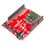
SparkFun Photon RedBoard
Aside from the form-factor, the Photon RedBoard is nearly identical to a
Particle Photon: same microprocessor, an RGB LED to indicate
connectivity or other states, and RESET and MODE buttons to help
configure the chip.
Covered In This Tutorial
The purpose of this tutorial is to familiarize you with all aspects of the
Photon RedBoard – both hardware and software – and to help get you
started down the path of Photon development. The tutorial is broken down
into a handful of sections, including:
• Board Overview – This section glosses over some of the Photon’s
hardware components and features.
• Getting Started – A step-by-step guide to connecting your Photon to
WiFi and Particle’s cloud.
• Arduino Shield (In)Compatibility – Despite the familiar size, the
Photon RedBoard isn’t quite Arduino-compatible. If you plan on using
it with shields, read through this section first.
Use the navigation bar on the right to find your way through.
Suggested Reading
�Page 2 of 13
This tutorial builds on a few electronics concepts you should be familiar
with. If any of the topics below sound foreign to you, consider checking out
those tutorials before continuing on.
• Logic Levels – The Photon RedBoard operates at 3.3V. This tutorial
will explain the difference between 3.3V and 5V devices.
• Analog to Digital Conversion – The Photon RedBoard features a
number of 12-bit ADC inputs. ADC’s help us convert the analog world
into the digital values a microcontroller can understand.
• Light-Emitting Didoes (LEDs) – LEDs are key on the Photon
RedBoard. They help to relay connectivity or diagnostic status.
Board Overview
The Photon RedBoard is a mash-up of the Particle Photon and the
SparkFun RedBoard. There are features from each of those boards in the
layout:
For a quick summary of the board’s components:
• External Supply: A barrel jack power supply can be used to power
the Photon with a voltage between 4.5-15V.
• LEDs
◦ Power: A red LED indicates that the board is receiving power.
◦ RGB: This LED displays the state of the Photon RedBoard’s
P1 module – whether it’s connected, connecting, or in DFU
mode.
◦ D7: This LED is attached to the Photon’s D7 pin. It’s a handy
debugging tool.
• Headers
◦ Power: The power header delivers GND, 3.3V, USB voltage
(~4.8V), and the external supply voltage (VIN).
◦ Analog: Six of the Photon’s analog-to-digital (ADC) pins are
broken out here.
◦ 8-pin Digital: The Photon’s hardware UART (RX & TX) and
digital pins D2-D7.
◦ 10-pin Digital: A mish-mash of unique pins – like the digital-toanalog output (DAC) – plus SPI and I2C interfaces.
◦ Spare: Bonus GPIO! These “spare” pins aren’t enabled in the
Particle firmware yet, but it’s coming.
• Buttons
◦ Reset: The reset button can be used to re-start the Photon
module.
◦ Mode: To switch between running, safe, listening, and DFU
modes.
• USB Connector: USB can be used to power the Photon RedBoard,
but it can also be used as a serial data interface.
�Page 3 of 13
• JTAG Header: The 20-pin JTAG header matches the pinout for an
ST-Link/v2 JTAG in-circuit debugger/programmer.
Photon I/O Pins
The Photon pinout doesn’t exactly match an Arduino – there just aren’t
enough pins. But the pins that are broken out have all sorts of extra
functionality. Here’s a summary of each of the pins and their capabilities:
Pin
Label
Name(s) – Function(s)
(Alternate names bolded)
Analog
Output
(PWM)?
5V
Tolerant
Digital
Input?
A0
A0
✔
A1
A1
✔
A2
A2
SS (SPI1)
A3
A3
SCK (SPI1)
✔
DAC2
A4
A4
MISO (SPI1)
✔
✔
A5
A5
MOSI (SPI1)
✔
✔
RX
RX (UART1)
✔
✔
TX
TX (UART1)
✔
✔
✔
✔
✔
✔
D2
D3
MOSI (SPI3)
CAN RX
MISO (SPI3)
I2S SD
JTAG TRST
D4
SCK (SPI3)
I2S SCK
JTAG TDO
✔
D5
SS (SPI3)
I2S WS
JTAG TDI
✔
D6
JTAG TCK
✔
D7
JTAG TMS
✔
A6
DAC
DAC1
A7
WKP
✔
✔
SS/A2
A2
SS (SPI1)
MOSI/A5
A5
MOSI (SPI1)
✔
✔
MISO/A4
A4
MISO (SPI1)
✔
✔
✔
✔
✔
✔
A3
SCK/A3
SCK (SPI1)
Analog
In
DAC2
SDA (I2C1)
SDA/D0
SCL/D1
✔
SCL (I2C1)
SPI1
SPI3
CAN TX
DAC
I2C
CAN
JTAG
I2S
�Page 4 of 13
Differences Between Photon RedBoard and Arduino Pinout
The Photon RedBoard maps most digital, analog, and serial interfaces to its
Arduino equal, but there are a few significant differences.
There are no explicitly digital Photon pins beyond D7, so you won’t find D8,
D9, D10, D11, D12, or D13. The Photon RedBoard breaks out DAC, WKP,
SS/A2, MOSI/A5, MISO/A4, and SCK/A3 in their place.
Double vision: A2, A3, A4, and A5 are broken out twice on the
Photon RedBoard! They can be found, obviously, on the analog input
header. But those pins also serve as the Photon's hardware SPI port,
so they're also broken out on the 10-pin digital header (and labeled
with their SPI purpose). More on that in the Arduino Shield (In)
Compatibility section.
The hardware UART pins – labeled RX and TX – are broken out where
you would expect to see D0 and D1. These pins can be used with the
Photon’s Serial1 class, or as digital inputs or outputs. For example…
pinMode(RX, OUTPUT); // Set RX pin as a digital output
digitalWrite(RX, HIGH); // Write RX pin HIGH
…will set the RX pin high.
The DAC and WKP pins serve as the Photon’s main digital-to-analog
output and wake-from-sleep input, respectively. But they can also be used
as analog inputs or digital inputs/outputs. To use the DAC pin as a analog
or digital I/O, reference it as A6; the WKP pin can be referenced using A7.
Pin Label
Alternate Analog Pin
WKP
A6
DAC
A7
The I2C pins at the top of the 10-pin header – SDA/D0 and SCL/D1 – are
where you’d expect to see them on any Arduino board (unless it’s a really
old Arduino). These pins can also be digitally referenced with D0 and D1 –
don’t confuse them with the RX and TX pins, though!
Also note that there is no AREF pin on the Photon RedBoard – that pin is
left as not-connected (and not labeled).
Power Supply Header
The 8-pin power header breaks out three possible voltage supplies, plus
ground and RESET – the Photon’s active-low reset signal.
Here’s a quick reference for the three voltage supplies on the header:
Pin
Label
Nominal Voltage
Voltage
source
Current Output
Limit
�Page 5 of 13
3.3V
3.3V
3.3V regulator
output
800mA
V-USB
4.8V (5V minus a
diode drop)
USB
500mA (fused)
VIN
4.5-15V
Barrel Jack
Depends on
external supply
3.3V! The Photon operates at 3.3V -- it is not capable of running at 5V!
Most digital pins are 5V tolerant, when configured as inputs, but the
analog pins are not!
RGB LED
The RGB LED on the Photon RedBoard identifies the connectivity status –
or other state information – of the P1 module. The color-to-mode mapping
of the Photon RedBoard is described in detail in Particle’s Device Mode
documentation. As a quick summary:
LED Color
Cyan
Cyan
Green
Blue
Pink
Pink
White
OrangeYellow
LED
activity
Device Mode
●
●
Breathing
Connected to WiFi and Particle Cloud
Blinking
Connected to WiFi, Connecting to
Particle Cloud
●
●
●
●
●
●
Blinking
Connecting to WiFi
Blinking
Listening mode (waiting for WiFi info)
Blinking
Receiving new application over-the-air
Breathing
Connected in safe mode
Breathing
Application running, WiFi off
Blinking
DFU mode
MODE and RESET Buttons
The RESET button – as with RESET buttons you may already be familiar
with – can be used to restart the Photon RedBoard’s application. After
pressing and releasing the button, the Photon will begin to boot up from
scratch, which means it’ll have to re-connect to WiFi.
The MODE button can be used to place the Photon in any number of
diagnostic modes, described in the Photon device mode documentation. It
can be used to boot into safe mode (connected to WiFi/Cloud, but no
application running), DFU mode, or to factory reset the device.
�Page 6 of 13
To place the Photon in any of those modes, begin by holding both RESET
and MODE down. Then release RESET, while still holding MODE. Release
the MODE button to leave the Photon RedBoard in the desired state.
The MODE button can also be used to place the Photon in listening mode
(to re-configure WiFi, check the firmware version, or module identity), while
an application is running. To accomplish that, hold the MODE button down
for about 4-5 seconds, until the RGB LED begins blinking blue.
Spare I/O Pins
Compared to the Photon’s P0 module, the P1 on the Photon RedBoard
delivers six extra GPIO pins. These are labeled as “spare” GPIO, and
broken out near the analog header. “S1” corresponds to “SPARE1”, “S2” is
“SPARE2”, and so on.
This header is not equipped with a connector – soldering to the pins is left
to the user.
At this time the spare GPIO are not implemented in Photon firmware,
but they should be usable in future releases.
Getting Started
The Photon can be powered over either USB (using a Micro-B Cable) or
with a 4.5-15V barrel jack power supply (like either our 5V and 9V wall
warts). To begin using your Photon RedBoard, plug it in!
�Page 7 of 13
The red “POWER” LED should illuminate to indicate the Photon RedBoard
is on. Once that’s verified, it’s time to set up WiFi.
Configuring WiFi, Connecting to Your Particle
Account
To use the Particle cloud – and their online IDE – you’ll need a Particle
account. Head over to build.particle.io to sign up, if you haven’t already.
C R EA T E A P A RT I C LE A CC O U N T !
When you power on a Photon RedBoard for the first time, it should boot up
into listening mode – indicated by a blinking, blue LED. It’ll remain in
listening mode until configured with your WiFi network and password.
There are a handful of ways to configure a Photon’s WiFi credentials,
including with the Particle smartphone app (iOS8+ or Android), or through
a serial terminal. Unless you’re very comfortable with serial terminals – or
just don’t have a smartphone nearby – we recommend using the app.
Both methods are described below, click one of the headings to expand
your section of interest:
Configuring WiFi with the Particle App
Configuring WiFi with a Serial Terminal
Tinkering
The Photon RedBoard ships with the Tinker application installed. If you
have a smartphone, this is a great tool for verifying your RedBoard’s
functionality, and to get a feel for the basics of electronics.
Load up the Particle app – now that your RedBoard is commissioned and
connected to your account, it should show up in your device list. And it
should have a green dot next to it, indicating it’s running the Tinker
application. Click the device to enter Tinker.
�Page 8 of 13
Select a Photon running the Tinker app to tinker with it.
The RedBoard has an LED attached to D7 – perfect for tinkering with.
Press “D7”, then select digitalWrite to set it as a digital output. It’ll
initially set itself LOW. To set D7 high, click the pin again. The blue D7 LED
should turn on almost instantly!
�Page 9 of 13
Set D7 as a digitalWrite() pin, then set it HIGH to turn the LED on.
Play around with the other pins. Try analog reading! See what voltage
those pins are floating at. Or attach some external LEDs and try analog
writing!
Arduino Shield (In)Compatibility
One of the Photon RedBoard’s most unique feature’s is its familiar Arduinoshaped form-factor, which makes it – at least mechanically – compatible
with most Arduino shields. Unfortunately, there’s a big difference between
mechanically compatible and electrically.
The SparkFun Weather Shield half works with the Photon RedBoard – the
digital sensors function over I2C, GPS communicates over the UART, but
trouble arises when you try to attach wind sensors to the analog pins.
Some Arduino shields will work with the Photon RedBoard, but many others
will not. Here’s what to watch out for when you consider loading the
RedBoard with a shield:
3.3V Logic
The most important distinction between an Arduino Uno and the Photon
RedBoard is the operating voltage. The Photon RedBoard’s P1 module
operates at 3.3V. That means the I/O pins will also operate between
0-3.3V. If a pin is configured for digital output, it will produce 3.3V for a logic
HIGH and 0V for a logic LOW.
Digital input range: In digital input mode, all pins except A3 and
DAC are 5V-tolerant – so they can handle logic HIGH's up to 5V.
(Internal pull-up resistors must be disabled if you plan on connecting
5V sources to input pins.)
Analog input range: The range of the analog input pins – if they're
used as analog inputs instead of digital – is limited to 0-3.3V. The
analog pins are not 5V-tolerant in ADC mode!
The power header does supply all of the voltage’s you’d expect. The
V-USB pin should supply about 5V (it’ll be closer to 4.8V). VIN will either
supply about 4.5V when powered by USB, or – if a barrel jack supply is
connected – the direct voltage supplied from the external jack.
D8-D13 and Duplicated A2-A5
�Page 10 of 13
A second key difference between an Arduino Uno and the Photon
RedBoard is the RedBoard’s lack of explicit GPIO from D8-D13. Where
you’d usually expect to see those labels, you’ll instead find a combination of
unique GPIO and duplicated analog pins – providing a hardware SPI port.
Watch out when using the 10-pin digital I/O header!
Duplicated A2-A5 pins: Note that the A2-A5 (SS, MOSI, MISO, and
SCK) are broken out to two places on the Photon RedBoard. You
can't use those pins for analog input and SPI communication
simultaneously.
Also note that, instead of D8 and D9, the DAC and WKP pins are broken
out. While they have unique functions themselves, these pins can be used
as digital inputs or outputs, or even analog inputs! You’ll just need to
remember to invoke them by their equivalent analog pin names: A6 (DAC)
and A7 (WKP).
Mismatched Analog Output Pins
In total, the Photon RedBoard offers more analog (PWM) outputs than an
Arduino Uno, but those analog outputs aren’t all in the same spot. The table
below provides a quick reference to matched, unmatched, and extra PWM:
Arduino
PWM Pins
Photon RedBoard
PWM Pins
–
RX (D0 position)
–
TX (D1 position)
–
D2
D3
D3
D5
–
D6
–
D9
WKP (D9 position)
D10
–
D11
MOSI/A5 (D11
position)
–
MISO/A4 (D12
position)
–
SDA/D0 (SDA
position)
–
SCL/D1 (SCL
position)
�Page 11 of 13
Photon
Only
Arduino
Only
PWM
Match
Pins 5, 6, and 10 – usually equipped with PWM on an Arduino – can not be
used for analogWrite() ‘ing. But there are a number of bonus PWM pins,
in the D0, D1, D2, D12, SDA, and SCL positions!
D0, D1, RX, and TX
Most of the digital pins from 0 to 7 are right where you’d expect them – all
of them except D0 and D1. In place of D0 and D1 are the Photon’s
hardware UART pins: RX and TX.
In code, these serial pins can be controlled with the Serial1 object (don’t
forget the ‘1’ – Serial without the ‘1’ is the USB port serial).
The RX and TX pins can also be used as digital inputs or outputs. Simply
use their labeled names to control or read their state. For example:
pinMode(RX, OUTPUT); // Set RX as an output
digitalWrite(RX, HIGH); // Write RX high
pinMode(TX, INPUT); // Set TX as an input
int txState = digitalRead(TX); // Read TX's logic level
Serial.print("TX's status is: " + String(txState)); // Print T
X's logic level over USB
D0 and D1 do still exist in Photon RedBoard world! They’re the alternative
names for the I2C pins, at the top of the 10-pin digital header. The can be
controlled using either D0 and D1 or SDA and SCL .
I2C Pins – Not on A4/A5
If you’re a veteran Arduino developer, you may remember a time – before
the Arduino Leonardo – when there weren’t explicitly broken out I2C pins
(SDA and SCL). Instead, those pins were broken out to the A4 and A5 pins.
That’s not the case on the Photon RedBoard! The I2C pins are only
broken out to the SDA and SCL pins!
Older shields that haven’t been updated to the “R3” layout may still have
the I2C pins connected to A4 and A5. If that’s the case, you may need to do
a bit of re-wiring before it can be functional with the Photon RedBoard.
No ICSP Header (for SPI)
The Arduino R3 footprint also introduced a greater need for the ICSP
header, which often carries SPI signals. Unfortunately, with a big-ol' module
hogging the edge of the board, there wasn’t a home for the ICSP header.
If you’re using a shield that requires SPI, but expects those SPI signals to
be delivered by the ICSP header (instead of pins 10-13), you may have to
do some re-routing on the shield.
Resouces & Going Further
The Photon RedBoard is open-source, so there are loads of resources
available should you need them:
• Photon RedBoard GitHub Repository – The EAGLE hardware design
files can all be found here.
• Photon RedBoard Schematic – A PDF of the Photon RedBoard’s
schematic.
• Windows Driver Installation guide – Windows users! To use the
Photon’s USB serial port, you’ll need to install a driver.
�Page 12 of 13
• P1 Datasheet – Particle’s web-hosted datasheet is a great resources
for questions dealing with the P1 module featured on the Photon
RedBoard.
• Particle Firmware Source – This is where you’ll find the latest
firmware available for all Particle development boards, including the
Photon RedBoard.
• Particle Documentation Home – Particle has loads of great
documentation, covering everything from getting started to a
firmware reference guide.
• USI WM-N-BM-14-S Datasheet – This is a datasheet for the WM-NBM-14-S module, which the P1 is based on.
As you continue developing firmware for the Photon RedBoard, we
encourage you to check out all of the development environment options
available. Check out our Photon Development Guide for more information!
Photon Development Guide
A UGUS T 20 , 201 5
A guide to the online and offline Particle IDE's to help aid you in your
Photon development.
And there are loads of other SparkFun tutorials that might help inspire your
next project, including:
Galileo Unread Email
Counter
How to create a simple unreademail checker with the Intel/Arduino
Galileo.
Pushing Data to
Are You Okay? Widget
Use an Electric Imp and
accelerometer to create an "Are You
OK" widget. A cozy piece of
technology your friend or loved one
can nudge to let you know they're
OK from half-a-world away.
Photon Weather Shield
�Page 13 of 13
Data.SparkFun.com
Hookup Guide
A grab bag of examples to show off
the variety of routes your data can
take on its way to a
Data.SparkFun.com stream.
Create Internet-connected weather
projects with the SparkFun Weather
Shield for the Photon.
https://learn.sparkfun.com/tutorials/photon-redboard-hookup-guide?_ga=1.34346849.1939... 9/29/2015
�


 工商网监
湘ICP备2023018690号
工商网监
湘ICP备2023018690号
