EVAL-315-KH2
EVAL-418-KH2
EVAL-433-KH2
WIRELESS MADE SIMPLE ®
KH2 SERIES BASIC EVALUATION KIT USER’S GUIDE
ORDERING INFORMATION
PART #
DESCRIPTION
EVAL-***-KH2
KH2 Series Basic Evaluation Kit
*** = 315, 418 (Standard), 433MHz
INTRODUCTION
Linx KH2 Series RF modules offer a simple, efficient, and cost-effective method of
adding wireless communication capabilities to any product. The basic Evaluation Kit
is intended to give a designer all the tools necessary to correctly and legally
incorporate the KH2 Series modules into an end product. The development boards
themselves serve several important functions:
• Rapid Module Evaluation - The boards allow the performance of the Linx KH2
Series modules to be evaluated quickly in a user’s environment.
• Range Testing - Using the on-board encoders and decoders to generate a
simplex transmission, a pair of development boards can be used to evaluate the
range performance of the modules.
• Design Benchmark - During the design process of your product, the boards
provide a known benchmark against which the performance of your own design
can be judged.
• Application Development - An on-board prototyping area is provided to allow a
designer to develop applications directly on the development board. All signal
lines are available on a breakout header for easy connection to the designer’s
circuits.
The purpose of this guide is to show the designer how to take full advantage of the
basic development boards included with the kit.
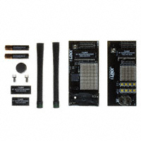
The kit includes 2 KH2 Series transmitters*, 2 KH2 Series receivers*, 2 extra PCBmount RP-SMA connectors, 2 development boards, 2 CW Series antennas, 1
CR2032 battery, 2 AAA batteries, and full documentation.
*One part is soldered to the board, one extra for use on your first prototype board.
Revised 11/17/11
�KH2 TRANSMITTER EVALUATION BOARD
THEORY OF OPERATION
TRANSMITTER EVALUATION BOARD
The transmitter board is powered by an on-board 3V CR2032 lithium battery. It
has eight SPST pushbutton switches, the state of which are encoded into a data
stream by the module. If a switch is closed, the module will capture the settings
of the 10-position DIP switch address bits and pushbutton states for encoding
and transmission. The transmitter will transmit continuously when any switch is
closed or when Transmit Enable (TE) is pulled high. This board has a prototyping
area with all of the transmitter lines brought out to a header for easy access by
external circuitry.
7
5
4
3
1
8
6
9
The receiver board is powered by two AAA batteries. The KH2 Series receiver
exhibits a sensitivity of greater than -112dBm, so under optimum line-of-sight
conditions, the transmitter / receiver link can operate over distances of up to
3,000 feet. The data recovered by the KH2 Series receiver is internally decoded.
If the settings of the 10-position DIP switch on the receiver board match the
address setting of the transmitter board, the data lines are updated to match the
state of the data lines (or pushbuttons) on the transmitter board. To demonstrate
this, one data line is used to drive a LED while another is used to activate a
buzzer. Switching transistors are used as drive buffers because the KH2 receiver
cannot directly source the current necessary to operate these devices. This
board has a prototyping area with all of the receiver lines brought out to a header
for easy access by external circuitry.
2
1.
2.
3.
4.
5.
6.
7.
8.
9.
Battery - 3VDC (use a CR2032-style battery only)
Power Switch
Momentary Pushbutton - S0 (D0)
Momentary Pushbutton - S1 (D1)
Continuous Transmit Switches
Prototyping Area
Reverse-Polarity SMA Antenna Connector
KH2 Series Transmitter Module
10-Position Address DIP Switch
USING THE KIT
KH2 RECEIVER EVALUATION BOARD
2
Using the kit is straightforward. Simply attach the antennas, turn on the power,
and press one or both of the buttons on the transmitter board. When S0 is
pressed, the buzzer will sound; when S1 is pressed, the LED will turn on.
3
7
4
1
6
5
RECEIVER EVALUATION BOARD
8
DEVELOPMENT USING THE PROTOTYPING AREA
In addition to their evaluation functions, the boards may also be used for actual
product development. They feature a prototyping area to facilitate the addition of
application-specific circuitry. This area has a connection to VCC at the top and
ground at the bottom that can be used to power the added circuitry.
NOTE: The CR2032-style battery on the transmitter board has very low current capacity,
with only about 3mA available for external circuitry. If added circuitry requires a higher
current, the battery must be removed and the board powered from an external source.
The holes are plated and set at 0.100” on center with a 0.040” diameter, making
it easy to add most industry-standard SIP and DIP packages to the board.
1.
2.
3.
4.
5.
6.
7.
8.
Page 2
Battery - 3VDC (use 2 AAA style batteries only)
Power Switch
Buzzer - D0
LED - D1
Prototyping Area
KH2 Series Receiver Module
Reverse-Polarity SMA Antenna Connector
10-Position Address DIP Switch
On the transmitter board, the data lines and the TE line from the encoder have
been wired out to a header on the right side of the prototyping area. On the
receiver board, the data lines from the decoder plus the PDN, and DATA lines
from the receiver have been wired out. This allows for easy access to connect
external circuitry to the modules, the encoder, and the decoder. Data line D0 is
connected to the buzzer and D1 is connected to the LED.
Page 3
�RANGE TESTING
Several complex mathematical models exist for determining path loss in many
environments. These models vary as the transmitter and receiver are moved
from indoor operation to outdoor operation. Although these models can provide
an estimation of range performance in the field, the most reliable method is to
simply perform range tests using the transmitter and receiver in the intended
operational environment.
Simple range testing can be performed with the transmitter and receiver
evaluation boards. To prepare the board for range testing, ensure that the
address line DIP switches on both boards are identically set. Turn on the boards
by switching the power switch to the ON position. Pressing S0 on the transmitter
will activate the buzzer on the receiver board, while S1 activates the LED. Sliding
switch SW0 or SW1 to the right will cause the transmitter to continiously transmit.
This will allow the designer to turn on the transmitter and walk with the receiver.
As you near the maximum range of the link in your area, it is not uncommon for
the signal to cut in and out as you move. This is normal and can result from other
interfering sources or fluctuating signal levels due to multipath effects. This
results in cancellation of the transmitted signal as direct and reflected signals
arrive at the receiver at differing times and phases. The areas in which this
occurs are commonly called “nulls” and simply walking a little farther will usually
restore the signal.
Since the evaluation boards are intended for use by design engineers, they are
not FCC certified. The transmitter has been set to approximate legal limits by
resistor R1 so that the range test results will approximate the results from a welldesigned, certified product. For applications where Part 15 limits are not
applicable or output levels can be legally raised due to protocol duty cycle, R1
can be changed according to the graph on Page 3 of the KH2 Series Transmitter
Data Guide.
To achieve maximum range, keep objects such as your hand away from the
antenna and ensure that the antenna on the transmitter has a clear and
unobstructed line-of-sight path to the receiver board. Range performance is
determined by many interdependent factors. If the range you are able to achieve
is significantly less than specified by Linx for the products you are testing, then
there is likely a problem with either the board or the ambient RF environment in
which the board is operating. First, check the battery, jumper routing, and
antenna connections. Next, measure the receiver’s RSSI voltage with the
transmitter turned off to determine if ambient interference is present. If this fails
to resolve the issue, please contact Linx technical support.
ABOUT ANTENNAS
The choice of antennas is one of the most critical and often overlooked design
considerations. The range, performance, and legality of an RF link are critically
dependent upon the type of antenna employed. Linx offers a variety of antenna
styles that you may wish to consider for your design. Included with your kit is a
Linx CW Series connectorized whip antenna that should be connected prior to
using the kit. Despite the fact that the antenna is not centered on the board’s
ground plane, it exhibits a VSWR of