Skywire™ Development Kit User Manual
NimbeLink Corp
Updated: March 2016
PN 30005 rev 10
© NimbeLink Corp. 2016. All rights reserved.
1
�
1. Introduction
1.1 Orderable Part Numbers
1.2 Product Overview
1.3 Block Diagram
2. Connect to Kit using a PC
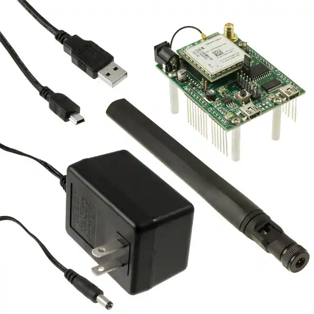
2.1 Unpack Kit Contents
2.2 Skywire™ Placement
2.3 Attach Antenna to Baseboard
2.4 Ensure header J6 is shorted with 2 pin Jumper
2.5 Plug in 12V Power Supply to connector J15
2.6 Plug USB cable into connector J14 and PC
2.7 Press and hold button S1 to power on the modem
2.8 Open Tera Term or similar terminal emulator
2.9 Test Serial Communication
2.10 Test Signal Strength
2.11 Activate Modem (onetime step)
2.12 SIM Card Detection (GSM Only)
2.13 Send Modem Activation String (1xRTT and EVDO only)
2.14 Setup PDP Context (GSM and LTE Only)
2.14.1 For GSM Modems
2.14.2 For the Verizon CAT3 LTE Skywire™
2.14.3 For the Verizon CAT1 LTE Skywire™
2.15 Test Network Communication
3. Common Next Steps
PN 30005 rev 10
© NimbeLink Corp. 2016. All rights reserved.
2
�
1. Introduction
1.1 Orderable Part Numbers
Description
Carrier
Network
Type
Skywire Development Kit
Any
Any
NLSW1xRTTA
2G 1xRTT
Aeris
CDMA
NLSW1xRTTS
2G 1xRTT
Sprint
CDMA
NLSW1xRTTV
2G 1xRTT
CDMA
NLSWGPRS
2G GPRS
Verizon
Any GSM (AT&T,
TMobile, etc.)
NLSWEVDOA
3G EVDO, GPS, GLONASS
Aeris
CDMA
NLSWEVDOV
3G EVDO, GPS, GLONASS
Verizon
Any GSM (AT&T,
TMobile, etc.)
Any GSM (AT&T,
TMobile, etc.)
CDMA
Any EU GSM
Any GSM (AT&T,
TMobile, etc.)
GSM
Verizon
Any GSM (AT&T,
TMobile, etc.)
CDMA
Any EU GSM
GSM
Verizon
CDMA
Orderable Device
NLSWDK
NLSWHSPA
3G HSPA+, GPS, GLONASS, GLOBAL BANDS
NLSWHSPAP
3G HSPA+
NLSWHSPAPE
3G HSPA+, European Version
NLSWHSPAPG
3G HSPA+, GPS, GLONASS
NLSWLTETSVG
LTE without Fallback, GPS, GLONASS
NLSWLTETNAG
NLSWLTETEUG
LTE with HSPA+ Fallback, GPS, GLONASS
LTE with HSPA+ Fallback, GPS, GLONASS,
EU
NLSWLTEGELS3
LTE CAT1, Verizon
GSM
GSM
GSM
GSM
GSM
1.2 Product Overview
The Skywire™ Development Kit includes one baseboard, antenna, power supply, SIM cards, and
debug cables. Skywire modems must be purchased separately. The kit enables you to develop your
application directly on the Skywire™ modem with three different ways to connect:
● Connect your PC to the xE910 modem UART port via onboard USBtoUART converter and
send AT commands directly to the modem through PC terminal applications. You can also
connect over USB for access to multiple COM ports.
● The kit is an Arduino shield, so you can plug the kit directly onto an Arduino microcontroller.
Please see Section 3: Common Next Steps for links to example documentation.
PN 30005 rev 10
© NimbeLink Corp. 2016. All rights reserved.
3
�
● To connect the kit to a different processor or development kit, a 14pin header breaks out the
necessary signals for easy connection to any device. The modem supports I/O levels from
1.655.5V, simplifying connection to other systems.
1.3 Block Diagram
*X2 and X3 U.FL connectors not present on all modems.
PN 30005 rev 10
© NimbeLink Corp. 2016. All rights reserved.
4
�
2. Connect to Kit using a PC
This section covers how to connect your development kit to a PC and provision the modem with your
cellular plan. It also covers how to communicate over the serial port to the Telit x910 modem which
only requires the use of USB port and connector marked J14 or USB2 in the diagram below. USB1
(connector J5) is used for Telit firmware updates to the modem and is not used in this section.
2.1 Unpack Kit Contents
PN 30005 rev 10
© NimbeLink Corp. 2016. All rights reserved.
5
�
2.2 Skywire™ Placement
To mount your Skywire™ Cellular modem follow these steps:
1. Gather the following:
a. Skywire™ Development Kit board
b. Skywire™ Cellular Modem
c. U.FL extractor tool (Always use a U.FL extractor tool when placing or removing U.FL
cables on the Skywire™ modem to avoid damaging the U.FL connectors).
2. Line up your Skywire’s™ cellular U.FL connector(s) on the side of the board closest to the
antenna connector. Depending on the type of Skywire™ Modem you have there may be one,
two, or three U.FL connections.
3. To avoid damage to the U.FL connector and maximize connector life, a U.FL removal tool
should be used when attaching/removing the U.FL connector. Always insert and remove the
U.FL connector with a force perpendicular to the board. If your Skywire™ is using GPS, attach
the GPS antenna to the bottom of the Skywire™ connector X3. If you are not using your
Skywire’s™ GPS or if your Skywire™ does not support GPS, continue to step 4.
4. Attach the U.FL cable to the top U.FL connector X1 on the Skywire™. If you are using a
Skywire™ with the cellular diversity antenna option attach a second antenna to connector X2.
5. Carefully seat your Skywire™ into the board’s Skywire™ socket (U1). Take care to ensure that
the pins are correctly aligned. Failure to properly align the pins may damage your Skywire™.
A properly mounted Skywire Modem with U.FL cable attached to top U.FL connector X1
TM
A common issue is accidentally inserting the modem with pins misaligned
by one row. Check pin alignment BEFORE applying power to prevent
modem damage.
PN 30005 rev 10
© NimbeLink Corp. 2016. All rights reserved.
6
�
2.3 Attach Antenna to Baseboard
Antenna screws onto SMA connector with a clockwise rotation
2.4 Ensure header J6 is shorted with 2 pin Jumper
This enables USB to UART communication between the PC and the modem.
PN 30005 rev 10
© NimbeLink Corp. 2016. All rights reserved.
7
�
2.5 Plug in 12V Power Supply to connector J15
2.6 Plug USB cable into connector J14 and PC
PN 30005 rev 10
© NimbeLink Corp. 2016. All rights reserved.
8
�
2.7 Press and hold button S1 to power on the modem
Please see the table below for the length of time needed to hold down button S1 for your particular
modem.
Device
NLSW1xRTTA
NLSW1xRTTS
NLSW1xRTTV
NLSWGPRS
NLSWEVDOA
NLSWEVDOV
NLSWHSPA
NLSWHSPAP
NLSWHSPAPE
NLSWHSPAPG
NLSWLTETSVG
NLSWLTETNAG
NLSWLTETEUG
NLSWLTEGELS3
Hold Time (th) for Button
S1 To Reset the Modem
1 second 5 seconds
tw > 10 seconds
1 second 10 seconds
th > 5 seconds
tw > 10 seconds
1 second
很抱歉,暂时无法提供与“NL-SWDK-LTE-TSVG”相匹配的价格&库存,您可以联系我们找货
免费人工找货