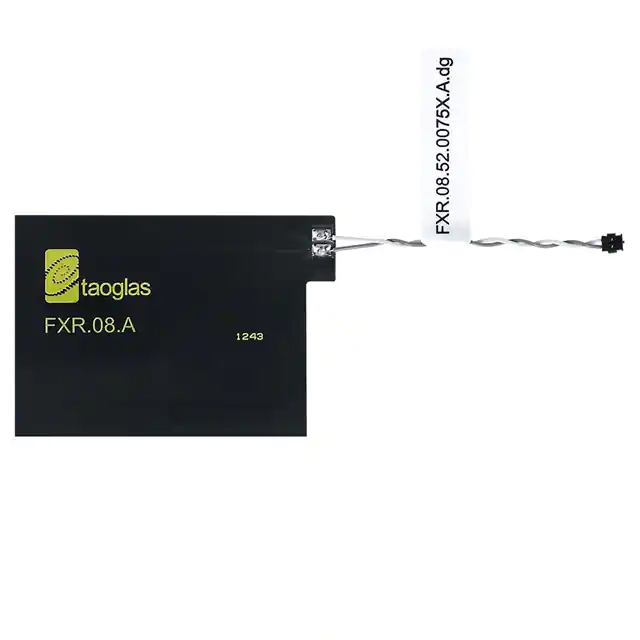
FXR.08.52.0075X.A.DG 数据手册
SPECIFICATION
Part No.
:
FXR.08.52.0075X.A.dg
Product Name
:
Rectangular Flexible Near-Field
Communications Ferrite Antenna with 75mm
Twisted Pair 28AWG Cable and ACH(F)
connector
Features
:
13.56 MHz RFID / NFC Antenna
Layered with Ferrite Flux Director
Low Profile Embedded Antenna
Dimensions: 53.34 mm x 37.3 mm
Thickness: 0.30 mm
Peel and stick Nitto UTD-30 adhesive on back
75mm Twisted Pair 28AWG Cable with Teflon and ACH(F)
Connector
Customized solutions available
RoHS Compliant
SPE-15-8-079/A/CM Page 1 of 10
�
1.
Introduction
The FXR.08.52.0075X.A.dg is an NFC Ferrite antenna with 75mm twisted pair
28AWG cable and JST connector. It works with specific NFC chips which need to
connect via JST ACH connector.
NFC antennas can be applied in areas not traditionally available to other types of
antennas. A common example is the ability to apply NFC antennas to batteries or
other conductive surfaces. To enable this usage, however, a ferrite flux director
layer is required. This ferrite layer acts to steer the magnetic flux away from the
metal or other conductor, where it would otherwise result in loss or complete failure
to communicate. Taoglas NFC antennas can therefore be customized with flux
director layers to enable this flexibility in usage. The coil inductance noted below
can help estimate a capacitance value for creating resonance at 13.56MHz.
Typical applications
-
Mobile devices
-
Electronic wallets
-
Health care ID scanners
-
Payment readers
-
Office ID
-
Access control
-
Internet Of Things
Customized antennas for specific applications, shape, and impedance match can also
be provided for an NRE and subject to MOQ. Contact your regional Taoglas sales
office for more information and support on our NFC antenna range.
SPE-15-8-079/A/CM Page 2 of 10
�
2.
Specification
Flexible PCB Near-Field Communications Antenna
Frequency
13.56
MHz
Inductance @ 13.56 MHz
4.5
µH
Flexible NFC Mechanical
Cable Length
Dimensions: 53.34 mm x 37.3 mm
Thickness: 0.15 mm
75 mm
Connector Type
ACH(F)
Adhesive
3M 467
Weight
3g
Antenna Dimensions
Ferrite Sheet Mechanical
PET
Ferrite Sheet
Adhesive Type
Dimension: 53.34*37.3 mm
Thickness: 0.02 mm
Dimension: 53.34*37.3 mm
Thickness: 0.10 mm
Nitto UTD-30 (W)
Thickness: 0.03 mm
Environmental
Operation Temperature
-40°C to 85°C
Storage Temperature
-40°C to 85°C
Humidity
Non-condensing 65°C 95% RH
SPE-15-8-079/A/CM Page 3 of 10
�
3.
Antenna Application
3.1. Test setup
A test fixture is used to measure the maximum interrogation distance. The
FXR.08.52.0075X.A.dg antenna is connected to a NFC evaluation board and then
placed on the fixed part of the fixture.
Evaluation
Board
Test
Fixture
Passively
Powered Tag
Sample on thin
plastic sheet
Measuring
Scale
Measurement
Arm
RFID Reader
Module
Antenna
The test sample is placed on a thin sheet of plastic connected to the movable part of
the fixture. Then the distance is carefully adjusted until the reader can no longer read
the sample, thus the maximum interrogation distance is displayed in the ruler.
SPE-15-8-079/A/CM Page 4 of 10
�
3.2. RFID tags used for test
A total of 8 RFID tags were used to measure the interrogation distances. The next
picture shows type 1 and type 2 tags, respectively.
Type 1
Type 2
Type 1 tag is based on ISO/IEC 14443A standard and has 512 bytes of memory.
Type 2 tag is based on ISO/IEC 14443A standard and has 192 bytes of memory.
The next picture shows the Tag-it HF-I RFID tags from Texas Instruments: RI-102112, RI-I11-112, RI-I03-112, RI-I16-112, button type, and RI-I17-112.
The Tag-it HF-I Plus Transponder Inlay family of Texas Instruments RFID is based on
the ISO/IEC 15693 standard for contactless integrated circuit cards (vicinity cards)
and ISO/IEC 18000-3 standard for item management.
SPE-15-8-079/A/CM Page 5 of 10
�
3.3. Matching
The interrogation distances presented here were taken with the antenna connected
directly to the evaluation boards with the default matching circuit. This is not
necessarily the optimal matching circuit that could be designed for a particular
antenna. We kept the default matching of each evaluation board to minimize the
number of variables in testing and keep integration as simple as possible.
As with any matching network the exact circuit and values for an optimal network
depend on the combination of antenna, NFC circuit, any intervening transmission line
and the environment presented to the antenna. These factors are specific to the
particular end product.
As a starting point, to achieve the read range results presented here, use the
matching network detailed in the schematic of the evaluation board for your particular
NFC chip and keep the antenna free of any obstruction. Once you can demonstrate
successful reads you can then optimize performance as desired.
If the matching network is required, you should implement the following topology:
The matching circuit should be designed to match the IC impedance 𝑍"# to 100Ω and
then connect the antenna through a 100Ω differential pair.
SPE-15-8-079/A/CM Page 6 of 10
�
3.4. Test Results
A total of 8 sample devices were used to measure the interrogation distances in two
scenarios, over plastic and over metal, using the Texas Instruments TRF7970AEVM
evaluation board. The results are:
•
Over plastic:
Dimensions
(mm.)
Interrogation
Distance (mm.)
Topaz512 (Type 1)
43 x 43
12
NTAG203 (Type 2)
F 42
14
Tag-it HFI Plus RI-I11-112
45 x 45
21
Tag-it HFI Plus RI-I02-112
76 x 48
23
Tag-it HFI Plus RI-I03-112
38 x 22.5
10
Tag-it HFI Plus RI-I16-112
F 24.2
12
F 22
10
F 32.5
15
Dimensions
(mm.)
Interrogation
Distance (mm.)
Topaz512 (Type 1)
43 x 43
7
NTAG203 (Type 2)
F 42
9
Tag-it HFI Plus RI-I11-112
45 x 45
14
Tag-it HFI Plus RI-I02-112
76 x 48
16
Tag-it HFI Plus RI-I03-112
38 x 22.5
7
Tag-it HFI Plus RI-I16-112
F 24.2
9
F 22
8
F 32.5
11
Device
Button type
Tag-it HFI Plus RI-I17-112
•
Over metal:
Device
Button type
Tag-it HFI Plus RI-I17-112
SPE-15-8-079/A/CM Page 7 of 10
�
4.
Mechanical Drawing (Unit:mm)
SPE-15-8-079/A/CM Page 8 of 10
�
5.
Packaging
SPE-15-8-079/A/CM Page 9 of 10
�
Taoglas makes no warranties based on the accuracy or completeness of the contents of this document and reserves the right to
make changes to specifications and product descriptions at any time without notice. Taoglas reserves all rights to this
document and the information contained herein.
Reproduction, use or disclosure to third parties without express permission is strictly prohibited.
Copyright © Taoglas Ltd.
SPE-15-8-079/A/CM Page 10 of 10
�
FXR.08.52.0075X.A.DG 价格&库存
很抱歉,暂时无法提供与“FXR.08.52.0075X.A.DG”相匹配的价格&库存,您可以联系我们找货
免费人工找货- 国内价格
- 15+72.36465
- 35+71.03464
- 65+69.70463
- 100+67.04461
- 国内价格
- 6+119.16912
- 30+107.25101
- 国内价格 香港价格
- 1+109.704601+14.19322
- 35+81.1583635+10.50000
- 65+79.6163565+10.30050
- 100+76.61349100+9.91200
- 国内价格 香港价格
- 6+128.305196+16.59970
- 30+115.4659330+14.93860