Wireless Technology to Control and
Monitor Anything from Anywhere™
SNAP Node
End Device (SN111)
Demonstration Board
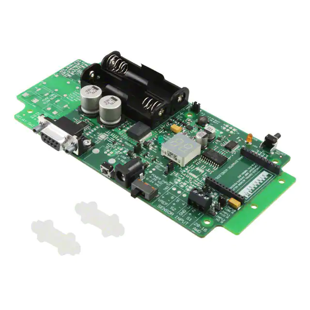
SN111 - End Device
The SNAP End Device has the onboard peripherals to demonstrate powerfulmonitoring and control
capabilities right out of the box. You can control external electrical devices withthe power-relay, display
link-quality or other parameters on the 7-segment LEDs, wake up with a button-press, and more.
Several of Portal’s sample scripts make specific use of these boards. Modify one of the sample scripts
to make your own application – demonstrate for yourself the power of SNAP!
SNAP Node End Device™ (SN111)
The SN111 End Device provides a latching relay for controlling external
devices, and a sensor input with jumper-selectable pullup resistors which
allows the connection of a number of off-the-shelf resistive sensor types
such as photocells and thermistors.
Compatible with all Synapse RF Engines
RS-232 port with full hardware flow control(UART1)
2-Digit 7-segment LED, softwarecontrollable
Status LED and select switch, also under users oftwarecontrol
Battery or external power option
USB port (UART0) which can also provide power
10A latching relay
Analog input terminals (ADC-CH0) 10-bit A/D with selectable pullup
�430-0112.01C
Wireless Technology to Control and
Monitor Anything from Anywhere™
SNAP Node End Device
(SN111)
Demonstration Board
Product Features
Feature
Part Selection
Part No.
Description
RS-232 Port..........................................Full RS-232 support with HW flow control (RTS/CTS)
Display ................................................2-digit seven-segment green LED Display
Input Power ..........................................4 - 9 VDC wall transformer, USB 5V (SN163 - Bridge only), 2x AA battery
Select Button........................................User function definable
Status LED............................................User function definable (yellow)
External Power LED ..............................On when external power from wall transformer or USB is supplied (green)
Power Switch ......................................On/Off switch for all power modes
Reset....................................................Reboot RF Engine
Relay ....................................................Contacts rated 10A at 250 VAC or 30 VDC. Replaceable fuse protection for relay circuit
Analog Input ........................................10-bit A/D input, 0-3.2V range. Jumper selectable pullup resistors: 10k, 100k, 1M
SN111F5-NR............End Device
RF Engine Socket Allocationon Demonstration Board
Pin No.
Name
Direction
Description
Demonstration Board Connection
1
2
3
4
5
6
7
8
9
10
11
12
13
14
15
16
17
18
19
20
21
22
23
24
GND
GPIO0_TPM1CH2
GPIO1_KBI10
GPIO2_KBI11
GPIO3_RX_UART0
GPIO4_TX_UART0
GPIO5_KBI4_CTS0
GPIO6_KBI5_RTS0
GPIO7_RX_UART1
GPIO8_TX_UART1
GPIO9_KBI6_CTS1
GPIO10_KBI7_RTS1
GPIO11_AD7
GPIO12_AD6
GPIO13_AD5
GPIO14_AD4
GPIO15_AD3
GPIO16_AD2
GPIO17_AD1
GPIO18_AD0
VCC
PTG0/BKDG
RESET_L
GND
Bidirectional
Bidirectional
Bidirectional
Input
Output
Bidirectional
Bidirectional
Input
Output
Bidirectional
Bidirectional
Bidirectional
Bidirectional
Bidirectional
Bidirectional
Bidirectional
Bidirectional
Bidirectional
Bidirectional
Bidirectional
Bidirectional
-
Power Supply/Return
GPI/O, or Timer1 Channel 2
GPI/O, Keyboard In
GPI/O, Keyboard In
UART0 Data In
UART0 Data Out
GPI/O, Keyboard In, or UART0 CTS
GPI/O, Keyboard In, or UART0 RTS
UART1 Data In
UART1 Data Out
GPI/O, Keyboard In, or UART1_CTS
GPI/O, Keyboard In, or UART1_RTS
GPI/O, or Analog In
GPI/O, or Analog In
GPI/O, or Analog In
GPI/O, or Analog In
GPI/O, or Analog In
GPI/O, or Analog In
GPI/O, or Analog In
GPI/O, or Analog In
Power Supply
Background Debug Communication
Module Reset, Active Low
Power Supply/Return
GND
Status LED
Select Switch
ADC - 24-bit CS
SYNAPSE Wireless, Inc.
®
All specifications are subject to change without notice. © 2012 SYNAPSE All Rights reserved. Patents pending.
MAX232
MAX232
MAX232
MAX232
ADC-24-bit DATA
ADC-24-bit CLK
LED - 7 seg CLK
LED - 7 seg DATA
Battery level (analog)
Relay RESET
Relay SET
Sensor Input
VCC
PTG0/BKDG
RESET
GND
500 Discovery Drive, Huntsville, Alabama 35806
877 982-7888 · synapse-wireless.com
�
很抱歉,暂时无法提供与“SN111F5-NR”相匹配的价格&库存,您可以联系我们找货
免费人工找货