| | WWW.CROUZET-CONTROL.COM
| | 56
| | PNEUMATICS PRODUCTS
| | WWW.CROUZET-CONTROL.COM
| | 57
| | PNEUMATICS PRODUCTS
Mounting accessories
Also available in ATEX version
for use in potentially explosive
atmospheres in accordance
with 94/9/EC Directive
81 533 501
Hole domino
Mounting equipment
Supply manifold 13 outputs
81 533 001
Clip domino
-
-
8
For mounting on
the end of a
zinc-coated mild
steel rod
Ø 8 mm on an
asymmetrical
DIN rail
-5 ➞ +50
4
For adjustable
mounting on a
zinc-coated mild
steel rod
Ø 8 mm on an
asymmetrical
DIN rail
-5 ➞ +50
79 450 609
Bar clips
Ø8
-
81 536 801
Characteristics
Weight (g)
Operating temperature
°C
80
Packet of 100
pieces
80
-5 ➞ +50
-5 ➞ +50
Dimensions
81 536 804
Mounted on steel rod Ø 8 mm
35
8Ø
Input port 8Ø
mm
push-in fitting
35
25
67
Ø8
Ø4
13 outputs
push-in fittings
4 mm Ø
67
80
80
Ø4
25
Push-in connection for semi-rigid
tubing Ø 4 mm (NFE 49100)
Other information
Use Weidmuller plastic labels for marking components part number FW 4734-6.
ATEX version products are available in the following catologues: Pneumatic products for explosive atmospheres or on our website
www.crouzet.com
ELECTRO-PNEUMATIC
CONTROL VALVES
�| | WWW.CROUZET-CONTROL.COM
| | 58
| | PNEUMATICS PRODUCTS
| | WWW.CROUZET-CONTROL.COM
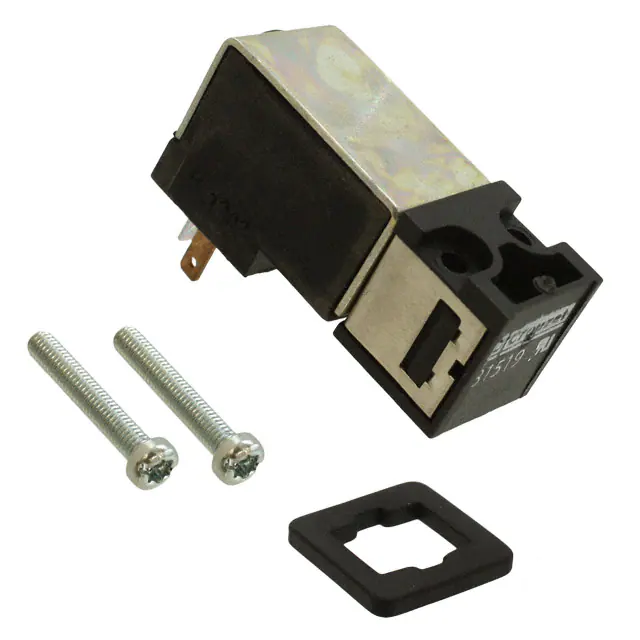
Miniature solenoid valves for alternating current
| | 59
| | PNEUMATICS PRODUCTS
Miniature solenoid valves for direct current
› Conform to the Low Voltage Directive
› For mounting on sub-base or footprint in accordance
with CNOMO recommendation E‑06-36-120N
Also available in ATEX version for use in potentially explosive atmospheres in accordance with
94/9/EC Directive
› Conform to the Low Voltage Directive
› For mounting on sub-base or footprint in accordance
with CNOMO recommendation E‑06-36-120N
Part numbers (and voltages)
Part numbers (and voltages)
81
81
81
81
519
519
519
519
380
381
378
379
81
81
81
81
519
519
519
519
680
681
678
679
3/2 NC
Without
manual
override
3/2 NC
With manual
override by
impulse
3/2 NC
With manual
override by latching (1/4 turn)
1➞ 8
0.5
12
0.12
5 ➞ 15
5 107
-10 ➞ +50
1➞8
0.5
12
0.12
5 ➞ 15
5 107
-10 ➞ +50
Characteristics
bar
Operating pressure
1➞ 8
mm
Orifice diameter
0.5
Nl/min
Flow at 6 bars
12
kV 0.12
ms
Switching time
5 ➞ 15
Mechanical life (operations)
5 107
°C
-10 ➞ +50
Operating temperature
Compressed air or inert gas - oil-free
●
air filtered to 50 µ
100 % ED
Duty factor
F
Insulation class
IEC 85
35
Weight
●
Rotatable connector 4 positions in 90° steps
IP 20
Degree of
with sub-base (page 62)
IEC 529
IP 65
protection
with connector 81 516 082 (page 65)
IEC 529
MH 15085
UL and cUL approval
15x15 mm footprint
Dimensions
81 519 0
according to CNOMO E 06-36-120N
6 min.
26
●
IP 20
IP 65
MH 15085
9,4±0,1
Adjacent side of footprint when valves mounted
in bank
2 or 3 Ø 1.6 min 2 max
81 519 632
3/2 NC
With maintained
manual override
81 519 340
3/2 NF
With maintained
manual override
1➞ 8
0.8
25
0.3
5 ➞ 15
5 107
-10 ➞ +50
1➞ 8
0.8
25
0.3
5 ➞ 15
5 107
-10 ➞ +50
1➞ 8
0,8
25
0,3
5 ➞ 15
5 107
-10 ➞ +50
●
100 % ED
F
35
●
100 % ED
F
35
●
100 % ED
F
35
●
●
●
–
–
–
IP 65
MH 15085
IP 65
MH 15085
IP 65
MH 15085
2 x M3 - 6 H depth 6
Solenoid valve projecting
on this side
1 - Supply
2 - Output
3 - Exhaust
9 min.
7,5 min.
3
2 1
1,4
3,8
7,5 min.
3,8
2 or 3 Ø 1.6 min 2 max
Adjacent side of footprint when valves mounted
in bank
7,5 min.
3,8
81 519 332
3/2 NC
With manual
override by
impulse
according to CNOMO E 06-36-120N
17 min.
2 1
81 519 032
3/2 NC
Without
manual
override
bar
Operating pressure
1➞ 8
mm
Orifice diameter
0.8
Nl/min
Flow at 6 bars
25
kV 0.3
ms
Switching time
5 ➞ 15
Mechanical life (operations)
5 107
°C
-10 ➞ +50
Operating temperature
Compressed air or inert gas - oil-free
●
air filtered to 50 µ
100
%
ED
Duty factor
F
Insulation class
IEC 85
35
Weight
●
Rotatable connector 4 positions in 90° steps
–
Degree of
with M12 5-pin connector
IEC 529
IP 65
protection
with connector 81 516 082
IEC 529
MH 15085
UL and cUL approval
15x15 mm footprint
6 min.
Manual
override
Voltage
24 V c
Characteristics
81 519 3
81 519 6
42 max.
9,7
17 min.
3
●
100 % ED
F
35
Function
Version
7,5 min.
1,4
3,8
●
IP 20
IP 65
MH 15085
9 min.
2 x M3 - 6 H depth 6
Solenoid valve projecting
on this side
●
100 % ED
F
35
Consumption
1W
16
15
Encombrement
81 519 0
1 - Supply
2 - Output
3 - Exhaust
Manual
override
26
9,4±0,1
42 max.
16
15
Manual
override
9,4±0,1
42 max.
26
81 519 3
81 519 3
81 519 6
42 max.
Function
Version
81 519 080
-
9,7
Voltage
24 V a 50-60 Hz
48 V a 50-60 Hz*
110 V a 50-60 Hz
220 V- 230 V a 50-60 Hz
Consumption
2.5 VA
2.5 VA
2.5 VA
2.5 VA
21
15
21
ATEX version products are available in the following catologues: Pneumatic products for explosive atmospheres or on our website
www.crouzet.com
�| | WWW.CROUZET-CONTROL.COM
| | 60
| | PNEUMATICS PRODUCTS
| | WWW.CROUZET-CONTROL.COM
| | 61
| | PNEUMATICS PRODUCTS
Electro-pneumatic miniature control valves
Mounting
Miniature solenoid valves
Indicators
- LED seals
- LED
003229P51
Valve modules
- Poppet
3/2 monostable (17.5 mm)
4/2 monostable (17.5 mm)
- Slide valve
4/2 bistable (35 mm)
4/2 monostable spring-return (35 mm)
Sub-bases
003241 P51
For
miniature
solenoid valves
For valve modules
Double
Single
003234P5
Complete product
003233P5
�| | WWW.CROUZET-CONTROL.COM
| | 62
| | PNEUMATICS PRODUCTS
| | WWW.CROUZET-CONTROL.COM
Valve modules
| | 63
| | PNEUMATICS PRODUCTS
Sub-bases and end bases for miniature control valves
› Monostable, bistable
› 3/2, 4/2
Also available in ATEX version for use in potentially explosive atmospheres in accordance with 94/9/EC Directive
Also available in ATEX version for use in potentially explosive atmospheres in accordance with
94/9/EC Directive
81 513 100
81 513 600
81 513 200
81 516 200
81 516 100
Part numbers
Function
3/2 NC monostable 3/2 NO monostable 4/2 monostable
4/2 bistable
4/2 monostable
Symbol
Mounting
Version
Push-in connection for semirigid tubing (NFE 49100)
Sub-bases
End bases (pair)
Intermediate supply
module
14
Characteristics
3
1
Torque capacity
UL and cUL approval
2
17.5
3➞8
3
200
300
2.2
2.5
-10 ➞ +50
15
1.5 x 10⁷
38
17.5
3➞8
3
200
300
2.2
2.5
-10 ➞ +50
15
1.5 x 10⁷
38
17.5
3➞8
3
200
300
2.2
4
-10 ➞ +50
15
1.5 x 10⁷
38
35
2➞8
4
300
400
4
5
-10 ➞ +50
50
107
106
35
3.5➞8
4
300
400
4
5
-10 ➞ +50
50
107
106
Weight
Connections Pneumatic
Cabinet
81 513 011
Cabinet
81 513 001
-
-
mm2
3
MM15085
DIN rail 35 mm
3
MM15085
DIN rail 35 mm
DIN rail 35 mm
DIN rail 35 mm
g
55
110
86
44
81 513 011 - 81 513 001
2 - Pneumatic output
4/2 (NO)
4 - Pneumatic output
3/2 or 4/2 (NC)
2
2
4
4
Output at rest (NO)
Output at rest *
Output at rest *
Output operating (NC)
Note :
Each sub-base can accept
- sub-base 81 513 060-065 : 1 relay 3/2 or
4/2, width 17.5 mm
- sub-base 81 517 101-201 : 1 bistable
relay 4/2 (width 35 mm) or 2 relays 3/2 or
4/2 (width 17.5 mm)
Dimensions
81 513
Cabinet
35 mm
81 517 101
81 517 201
-
-
Ø 6 mm
Mounting
Characteristics
Width
mm
Working pressure
bars
Orifice diameter
mm
Flow at 6 bars
with Ø 4 mm sub-base (page 63)
with Ø 6 mm sub-base (page 63) Nl/min
Flow Rate
with Ø 4 mm sub-base (page 63) kV
with Ø 6 mm sub-base (page 63)
Operating temperature
° C
Switching time for the valve only ms
Mechanical life
operations
Weight
g
Ø 4 mm
Ø 6 mm
Ø 6 mm
Cabinet
17.5 mm
81 513 060
81 513 065
-
81 516
Electrical
02
2 Supply ports
03
2 Exhaust ports
Integral push-in connections Ø 6 mm
Degree of protection :
IP20 when assembled.
A1 - Pilot signal
A2 - Common
t
Earth
A1 - Operating
control signal
(14)
A2 - Common
A1 - Rest control
signal (12)
A2 - Common
t
Earth
Dimensions with miniature control valves (page 62) + miniature solenoid valves (page 58) + indicators (page 65)
End bases
Intermediate
base
LED indicator
80
Module
3
1
2
1
17,5
3
www.crouzet.com
1
17,5
3
6
5
35 x (n module
17,5 + 1)
35
Ø4
ATEX version products are available in the following catologues: Pneumatic products for explosive atmospheres or on our website
3
4
17,5
12,5
1
77 max.
Ø6
ATEX version products are available in the following catologues: Pneumatic products for explosive atmospheres or on our website
www.crouzet.com
�| | WWW.CROUZET-CONTROL.COM
| | 64
| | PNEUMATICS PRODUCTS
| | WWW.CROUZET-CONTROL.COM
Valves and solenoids valves assembled
| | 65
| | PNEUMATICS PRODUCTS
Accessories
Contact us for
Also available in ATEX version for use in potentially
explosive atmospheres in accordance with 94/9/EC Directive
Other versions
Part numbers
Part numbers
Ø 4 ext.
Ø 4 ext.
Solenoid valve
with manual override
by impulse
81 513 103
Solenoid valve
with manual override
by impulse
81 513 203
Symbol
Characteristics
3➞8
3
200
Operating pressure bar
Orifice diameter mm
Flow at
sub-base 81 513 060 NL/min
6 bars
sub-base 81 517 101 NL/min
with sub-base 81 513 060
KV
with sub-base 81 517 101
Operating temperature °C
Switching time of the assembly ms
Mechanical life (operations)
at 4 bars
Valve position will be maintained in the event
of pressure loss and/or electrical current loss
Mounting
3➞8
3
200
DIN rail 35 mm
DIN rail 35 mm
g
Weight
UL and cUL approval
Principle
of operation
130
MH15085
130
MH15085
Dimensions
-
-10 ➞ +50
20
-
-
-
-
-
-
-
-
-
81 513 064
(by 10)
(by 5)
Exhaust
Plug-in Ø 6
silencer
Plug-in Ø 8
Connector for solenoid valve
Without manual override
Pneumatic
With manual override
pilots
by impulse
Push-in connection for semi-rigid tubing
Ø 4 mm (NFE 49100)
Blanking plate
-
-
-
-
-
-
-
-
-
-
●
-
-
-
-
-
-
-
Instantané Ø 4 ext.
-
81 513 052
81 513 055
81 537 001
81 537 201
-
81 516 082
-
81 516 081
-
81 516 091
81 516 085
End bases - one pair
Intermediate
module
Module
LED
indicator
Consumption W
Temperature °C
Connection mm
Mounted between the pilot solenoid valve
and the body of the module
Supplied in multiples of 5
Supplied in multiples of 10
Packet of 10 pieces
g
Weight
6
-
0.24
- 10 ➞ +50
-
●
●
-
-
-
●
-
-
●
●
-
-
-
●
2
-
30
10
1
2
Connection
t
80
Poppet valve
3
1
2
1
Pneumatic indicator
17,5
3
1
4
3
17,5
Ø4
3
6
17,5 + 1)
3535
x (n module
●
3
Pilot
signal
Earth (4)
Dimensions
5
17,5
Ø6
End bases not supplied (page 63)
Intermediate bases not supplied (page 63)
Indicators not supplied (page 65)
12,5
1
Marking tag
5
●
77 max.
81 537 001 - 81 537 201
81 513 052 - 81 513 055
Mounted by plugging into push-in connector for semirigid tubing (NFE 49100)
81 513 058 - 81 513 059
81 516 082
+ 0,1
26
15,5 - 0
35
Electrical signal
- Common A2
- Pilot signal A1
- Earth
81 513 058
81 513 059
Characteristics
Manual override
4/2 bistable module
81 513 059
LED seal
12 to 24 V - DC - AC
Packaging
-
Plug-in solenoid valve
4/2 monostable module
-
1.5 x 10⁷
Common exhaust
Pneumatic output
-
Symbol
LED indicator
Common air supply
-
+ 0,1
Anti-return valve to prevent
back pressures
-
-10 ➞ +50
20
-
3/2 monostable module (NC)
-
15,5 - 0
1.5 x 10⁷
-
2.2
81 513 052
81 513 055
81 513 058
M3
2.2
24 V - 50-60 Hz c
48 V - 50-60 Hz c
110 V - 50-60 Hz c
230 V - 50-60 Hz
(-10% +6 %)
Visual
indicators
with anti-
surge
15
24 VDC (+10% -15%)
4/2 monostable
29
Voltage
3/2 NC
Ø 15
Function
Sub-base with push-in connection for semi-rigid
tubing (NFE 49100)
Version
50
28
15
Pg 7
Ø 14
ATEX version products are available in the following catologues: Pneumatic products for explosive atmospheres or on our website
www.crouzet.com
�| | WWW.CROUZET-CONTROL.COM
| | 66
| | PNEUMATICS PRODUCTS
| | WWW.CROUZET-CONTROL.COM
Solenoid valves
| | PNEUMATICS PRODUCTS
Miniature control valves, 17.5 mm
➜ Electro-pneumatic interface block
› Reduced "dimensions"
› Mounted on sub-base
Complete block, ready to install, consisting of:
■ Preconfigured 8-position sub-base
■ 6 4/2 monostable valve modules with 24 Vc pilot
holes
■ 2 blanking plates (for extension if necessary)
■ 1 connection cable
Part numbers and voltages
Function
Mounting
Solenoid valves
with
manual
override
by impulse
| | 67
24 V (+10% -15%)
24 V - 50/60 Hz (+10% -15%)
48V - 50/60 Hz (+10% -15%)
110 V - 50/60 Hz (+10% -15%)
220 - 230 V - 50/60 Hz (+10% -15%)
3/2 NC
On sub-base (54)
81 519 732
81 519 774
81 519 775
81 519 776
81 519 777
Part numbers
Symbol
Part numbers
IP 65
Electrical characteristics
Supply voltage
Courant max. absorbé sur le 24 V de SUBD (mA)
Courant absorbé par chaque électrovanne
Response time (ms)
LED display
Protection against voltage surges
Electrical connections
Type of cable
Cable length
Pneumatic characteristics
Function
1.5 x 10⁷
1
2.5
-5 ➞ +50
70
MH15085
Operating pressure bars
Flow at 6 bars NL/mim
Mechanical life (operations)
Working medium
Characteristics
Operating pressure
bar
Orifice diameter
mm
Flow at 6 bars
Nl/min
Rotatable coil 4 positions in 90° steps
Degree of protection (with connector
81 516 082 not supplied) (see page 65)
IEC 529
Mechanical life
operations
c W
Consumption
~ VA
Operating temperature
°C
Weight
g
UL and cUL approval
Principle of operation
Connections
●
Pneumatic
{
Electrical
{ t Earth
1 - Supply
2 - Output
Dimensions
81 519
Pneumatic connections
Power supply connection
Output connections
Connection of common exhaust
General characteristics
Operating temperature range IEC 68214 (oC)
Storage temperature IEC 68-2-14 (°C)
Protection (IEC/EN 60529)
Mounting
On separate sub-base
1 - 2 - Pilot signal
Weight (g)
Comments
Other configurations on request
Electrical connection by connector
81 516 062 (see page 65)
Dimensions (mm)
16 outputs
81513241
81513238
24 Vc ± -10%
500
60
15
Yes (integrated in the sub-base)
Yes
24 Vc ± -10%
500
60
15
Yes (integrated in the sub-base)
Yes
Sub D9 AWG 24 wires
2m
Sub D9 AWG 24 wires
2m
6 4/2 monostable valve
modules (81513200) + 2 free
positions
3 ➞8 b
300
1.5 x 10⁷
Compressed air or inert gas, 50
µm filtered non-lubricated air
Whitout
3 ➞8 b
300
1.5 x 10⁷
Compressed aire or inet gaés,
50 µm filtered non-lubricated air
Push-in connection Ø 8 mm
Push-in connection Ø 6 mm
Push-in connection Ø 8 mm
Push-in connection Ø 8 mm
Push-in connection Ø 6 mm
Push-in connection Ø 8 mm
-5 ➞ +50
-15 ➞ +50
IP 20
On DIN rail or via two M5
screws (according to mounting
plan)
1350
-5 ➞ +50
-15 ➞ +50
IP20
On DIN rail or via two M5 screws
(according to mounting plan)
Connections
81513241
Connector wiring
1
2
3
4
2
3
4
5
5
88,5
1
88,5
1-2
2→8
2.7
170
16 outputs
A
2
A
4
2
2
2
2
2
4
4
2
2
2
2
4
2
2
2
2
4
2
4
4
213213
EV1
EV1
......
…
2
E
6
E
4
7
8
6
9
93
EV6
EV6
1
1
EV
EV
1 Commun 0 V
2 Clips femelle Cl
1
2
1
Gemeinsam 0 V
2
Clips für Schienen Cl
7
8
9
1
1
93
2
960
�| | WWW.CROUZET-CONTROL.COM
| | 68
| | PNEUMATICS PRODUCTS
| | WWW.CROUZET-CONTROL.COM
| | 69
| | PNEUMATICS PRODUCTS
Specific islands "for integrators" (supplied in packs of 20)
Versions with interfaces 300 NL / mm
Configuration
1 - Specify the number and type of interfaces (3 / 2 mono 4 / 2 mono - 4 / 2 bistable) see page 62.
2 - Specify the voltage, the type and method of the control
valve connections, see page: 58-59 (Example: 24 V DC
with manual switch maintained, exit leads).
3 - Please send us your application specifying your
requirements and quantities per year, and we will respond
as soon as possible.
Versions with interfaces 30 NL / mm
Configuration
1 - Specify the voltage, the type and method of the control
valve connections, see page: 58-59 (Example: 24 V DC
with manual switch maintained, exit leads).
2 - Please send us your application specifying your
requirements and quantities per year, and we will respond
as soon as possible.
Develop customised versions to specifications
Crouzet analyses your needs and offers a customised
solution.
MULTI-FLUID
SOLENOID VALVES
�