Preface
1.
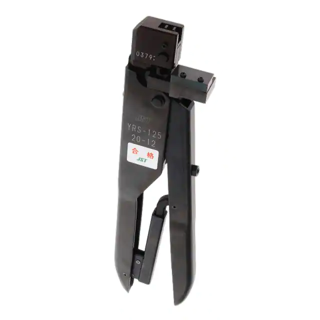
The YRS series hand tool crimps smaller sized chain (with open barrel)
terminals, and was designed to be used for small preproduction lots,
samples and repairs.
An upper die has two crimping positions. Set it depending on the
applicable wire size for each position.
This tool can crimp side-feeding terminals only.
2
As the crimp height of the tool is not adjustable, the applicable wires are
limited. So some tools come with two different upper dies.
IPrecautions
I
(1)
Make sure the correct combination of wire, terminal, and tool is used.
(2)
Because the tool has a ratchet, the handles will not open until the
terminal is completely crimped. Do not forcibly open the handles while
crimping. If you need to open the handles because, for example, a J'~
terminal is positioned incorrectly, or a foreign body is stuck in the crimp
tool, remove the adjustment pin and upper die, and squeeze handles
until the ratchet is released.
(3)
Check the following items before use; .
a. Make sure there are no scratches, rust, or dust on the crimping dies.
b. When crimping a terminal to a wire, does the ratchet operate normally
after the crimping dies are completely closed?
c. Are both the tensile strength and appearance adequate?
(4)
Do not use the crimp tool for purposes other than crimping.
(5)
Periodically add oil to the moving parts and the pins of the crimping tool.
If you don't plan on using the tool for a long time, apply oil to the entire
body of the tool, and put it in a rust preventive bag, or wrap it with a oiled
cloth before storing.
(6)
Consult with JST if the tool breaks or needs to be repaired.
�·.11. Names of each part
Upper die
......
\
__
-
__
/.Feeder
j
.
\,
.\
Handle
y •••••••
I
@
f
/ Ratchet
(.NI".lohl .......... ...,..··· ....... , .
I 2. Crimping Operation
(1)
Squeeze the handles until the dies are completely
closed. The ratchet will then releases .and the
handles will open.
(2)
Check the marking on the upper die. The
applicable wire size is shown there. Select the
correct position depending on the wire you will use.
Then correctly set the upper die, as shown in Fig.
1.
Applicable
wire size
Position the upper die so that the tail of the guide
screw is inserted in the guide groove of the upper
die (on the insulation barrel side). The die cannot be set when oppositely
mounted.
�Insert the strip carrier of the chain terminals in between the G)terminal guide
guide plate. Insulation barrels should be positioned in the groove of the
and
@ guide plate. Feed the chain terminals until the insulation barrel of the first
terminal comes to the center of the crimping position, while holding the strip
carrier by fingers, lighly pressing it forward notch by notch. Refer to Fig. 2 and
®
Guide plate
Terminal
groove
CD
(2)
Guide plate
(2)
Terminal
Cutter
""""--~~
Strip carrier
Fig.3
Fig.2
Insulation
barrel
crimping
Wire barrel
crimping die
die
Stripper
Grip the handles so the terminal is just
held in the dies. Do not put too much
pressure on the terminal at this point. If
you deform it, you may not be able to
insert the wire.
Position a stripped wire so that the
insulation edge is lighly pressed against
the stripper. See Fig. 4 in the left.
D-Ll
[1-yr--(---~_
FigA
Adequate amount of
bell-mouth
conductorgl"'"
as Shown.\~ot~ O.5mm
1
.
Remove the terminal and make a visual
inspection. See Fig. 5.
1t__
~':::arrel
completely
grips Ihe wire insulalion.
~hall
be
110
(1) Squeeze the handles to crimp the
terminal while holding the wire to keep it
in the correct position until the ratchet
releases.
(2)
HllH
很抱歉,暂时无法提供与“YRS-125”相匹配的价格&库存,您可以联系我们找货
免费人工找货- 国内价格 香港价格
- 1+10098.881591+1303.68100
- 2+9425.651992+1216.77270
- 国内价格 香港价格
- 1+14064.576571+1815.61900
- 5+13038.527655+1683.16468