M series
Connectors
ratchet coupling
®
®
�®
®
Precision modular connectors to suit your application
Since its creation in Switzerland in 1946 the LEMO Group has been recognized as a global leader of circular Push-Pull
connectors and interconnect solutions. Today LEMO and its affiliated companies, REDEL and COELVER, are active in
more than 80 countries with the help of over 40 subsidiaries and distributors.
Over 90000 connectors
The modular design of the LEMO range provides over 90000 connectors from miniature ø 3 mm to ø 50 mm, capable of
handling cable diameters up to 30 mm and for up to 114 contacts. This vast portfolio enables you to select the ideal connector
configuration to suit almost any specific requirement in most markets, including medical devices, test and measurement
instruments, machinery, audio video broadcast, telecommunications and military.
LEMO’s ratchet 3/4 turn connection system
This highly robust 3/4 turn screw locking system is recognized worldwide for the most demanding applications as a safe,
secure and quick screw mating system. Its special ratchet mechanisms provides ultra high reliability in the most severe
vibrations environments, shocks or pull on the cables.
Triple start thread
Triple start thread
l
3/4 turn locking
l
l
Very fast coupling nut engagement in the socket
Stable thread engagement making tilted nut engagement
impossible
3/4 turn locking
Spring loaded
ratchet system
Quick and fast connection requiring less than a full turn
for complete mating
l Full mating possible with a single hand movement
Spring loaded ratchet on locking nut
Secure mating in high vibration environments
No specific mating torque required to secure
l No tools required; hand torquing force is sufficient to secure
l
l
UL Recognition
LEMO connectors are components recognized by the Underwriters Laboratories (UL), facilitating the UL approval of the
complete system (including LEMO connector, cable and your equipment).
CE marking
CE marking
means that the appliance or equipment complies with the protection requirements of one or several European safety directives. CE marking
applies to complete products or equipment, but not to electromechanical components, such as connectors.
REACH and RoHS
LEMO connector specifications comply with the requirements of the RoHS directive (2011/65/EU) and REACH regulation
(1907/2006/EU) of the European Parliament and latest amendments. These REACH and ROHS regulations specify the
restrictions of the use of hazardous substances in LEMO products marketed in Europe.
Product safety notice & disclaimers
Please read and follow all instructions specified on the last page or on our website carefully and consult all relevent
national and international safety regulations for your application. Improper handling, cable assembly, or wrong use of
connectors can result in hazardous situations.
LEMO products and services are provided “as is.” LEMO makes no warranties or representations with regard to LEMO
product & services or use of them, express, implied or statutory, including for accuracy, completeness, or security.
In no event shall LEMO be liable for any direct, indirect, punitive, incidental, special consequential damages, to property
or life, whatsoever arising out of or connected with the use or misuse of LEMO’s products.
www.lemo.com
�®
®
Introduction
This catalogue provides a complete description of the LEMO M series portfolio. M series connectors are lightweight triplestart ratchet coupling type connectors designed for avionics, aerospace, military, security, motorsport and heavy duty
applications.
The M series is a COTS (Commercial Off-The-Shelf) product, that fulfills the harshest MIL-DTL-38999 requirements in a
more compact and lightweight package. It features a very wide range of configurable options to fulfill every applications.
The LEMO engagement for supplying innovative solutions which meets users highest expectations translates thought the M
series in a highly reliable interconnect solution that helps our customers reduce their maintenance and downtime in critical
applications.
The LEMO quality arises from years of expertise in design, manufacturing and quality system where all single M series
connectors get identified with a laser engraved part number and production batch number for full traceability from raw materials to fully assembled product.
Table of contents
Technical characteristics.................................................................................................................................................................................................... 2
M Series
Interconnections....................................................................................................................................................................................................... 4
Standard models part numbering system, Others part numbering system, Part section showing internal components.......................................... 5
Locking nuts options, Backshell options................................................................................................................................................................... 6
Standard models....................................................................................................................................................................................................... 7
Watertight model (unmated)................................................................................................................................................................................... 14
Vacuumtight model (unmated)................................................................................................................................................................................ 15
High Speed models................................................................................................................................................................................................ 16
USB 2.0 models...................................................................................................................................................................................................... 18
Fibre Optic models.................................................................................................................................................................................................. 19
High Power models................................................................................................................................................................................................. 21
Alignment key and Polarized keying system.................................................................................................................................................................. 23
Insert configuration
Multipole................................................................................................................................................................................................................. 24
Mixed multipole, Multipole high speed ethernet cat6.............................................................................................................................................. 26
USB 2.0, Multi fibre and Mixed fibre optic + low voltage, Mixed high speed coax.................................................................................................. 27
High Power............................................................................................................................................................................................................. 28
Contacts
Crimp, High speed ethernet cat6............................................................................................................................................................................ 30
Coaxial, High Voltage, High Power, F7 Fibre Optic................................................................................................................................................ 31
Accessories....................................................................................................................................................................................................................... 32
Tooling................................................................................................................................................................................................................................ 38
Panel cut-outs and PCB drilling pattern.......................................................................................................................................................................... 41
Assembly instructions...................................................................................................................................................................................................... 46
Product safety notice........................................................................................................................................................................................................ 49
MM
0M
1M
2M
3M
TM
4M
LM
5M
www.lemo.com 1
�®
®
Technical characteristics
Materials and treatments
Shell
material code 1)
Component
X C
l 2)
Outer shell, conical nut, coupling nut
l
L
I
l
Earthing crown
Material (Standard)
l 2)
l
Hexagonal nut
l
l
l
l
Surface treatment (µm)
chrome
nickel
gold
Aluminium alloy (AA 6262A or AA 6023)
–
5
–
Brass (UNS C 38500)
0.3
–
–
Aluminium alloy (AA 6262A or AA 6023)
anodized
Aluminium alloy (AA 6262A or AA 6023)
–
14
–
Bronze (UNS C 54400) or special brass
–
–
1.5
Brass (UNS C 38500)
–
3
–
Aluminium alloy (AA 6262A or AA 6023)
–
5
–
l
Brass (UNS C 34500)
–
–
1.0
Female crimp contact
l
Bronze (UNS C 54400)
–
–
1.5
Clips
l
Cu-Be or special steel
Insulator
l
PEEK
Ratchet
l
Special PEEK
Male crimp contact
O-ring
Sealing resin
l
l
EPDM (HYl)
l
Silicone
l
l
l
l
l
FPM/FKM (Viton®)
l
l
without treatment
Epoxy (Araldite®) (HEl)
l
Silicone (Elastosil®) (HYl)
Cable rear seal
l
Fluorosilicone
Spring
l
Stainless steel
Note: standards for surface treatment are as follows: chrome-plated SAE AMS 2460; nickel-plated SAE AMS QQ N 290 or MIL DTL 32119; gold-plated
ISO 27874.
1) X = Nickel-plated aluminium alloy (standard).
C = Chrome-plated brass.
L = Anodized aluminium.
I = NiCorAITM Nickel fluorocarbon polymer aluminium alloy.
2) anthracite colour.
l First choice alternative l Special order alternative
Electrical performance
Characteristics
Value
IEC international
MIL-spec tests
Insulation resist. (at ambient temp.) 1)
> 1012 Ω, > 1010 Ω (after humidity)
IEC 60512-2 test 3a
EIA-364-21
Dielectric withstanding volt. (sea level)
See table pages 24 to 28
IEC 60512-2 test 4a
EIA-364-20
Contact resistance 3)
See table below
IEC 60512-2 test 2a
EIA-364-06
Current rating
See insulator configuration pages 24 to 28
IEC 60512-3 test 5a
< 1.5m Ω
IEC 60512-2-6
Shell to shell conductivity 2)
Shielding effectiveness, low frequency
2)
Shielding effectiveness, high frequency
2)
EIA-364-83
≥ 80 dB up to 1GHz
EIA-364-66
≥ 70 dB (3GHz), ≥ 58 dB (6GHz), ≥ 40 dB (10GHz)
EIA-364-66
Contact resistance 3)
IEC 60512-2 test 2a
Value
0.5 0.7 0.9 1.3 4.0 5.0 6.0 8.0
ø A (mm)
≤ 8.3 ≤ 5.7 ≤ 4.2 ≤ 2.9 ≤ 0.3 ≤ 0.25 ≤ 0.2 ≤ 0.2
mΩ
Note: 1) after humidity test: 21 days at 95% RH according to IEC 60068-2. Insulation resistance measured between the
2) no shell to shell conductivity for anodized aluminium versions (shielding and conductivity values do not apply).
3) after 3000 mating cycles and the salt spray test according to IEC 60512-6 test 11 f.
contacts and contact/shell.
2 www.lemo.com
�®
®
Mechanical performance
Characteristics
Value
IEC international
3000 cycles
Endurance
Gunfire vibration
Vibration-Sine
1) 2)
Vibration-Random
2)
IEC 60512-5 test 9a
MIL-spec tests
EIA-364-09
25 to 2000 Hz, 3 axis (Apache helicopter)
MIL-STD-810F method 519.5
30 g, 3 axis, 12 hr
MIL-STD-202 method 204-G
50-2000 Hz, 37.8 g rms-3 axes; 4h amb
IEC 60512-6-4
EIA-364-28 test cond. V letter I
Shock 2)
300 g - 3 msec
IEC 60512-6-3
EIA-364-27 condition D
Acceleration
50 g acceleration
Torque
See table below
MIL-STD-1344 - 2011-1, A
Note:
1) amplitude: 30g. Frequency: 10 to 2000 Hz. Time per axis: 4 hours (X, Y, Z).
2) no signal discontinuity above 1 µs.
Plug mating / unmating torque
Series
Coupling torque
tightning (N.cm)
Coupling torque
untightning (N.cm)
Series
Coupling torque
tightning (N.cm)
Coupling torque
untightning (N.cm)
MM
8
4
TM
26
30
0M
4
5
4M
26
25
1M
10
11
LM
48
43
2M
20
14
5M
91
54
3M
34
29
Note: indicative values, tightening torque may vary depending on insert configuration.
Environmental performance
Characteristics
Value
IEC international
MIL-spec tests
Standard models operating
temperature (mated)
-55°C/+200°C (shell material code C + Silicone O-ring)
Ingress protection index (mated)
IP68 (at 2 m, 15Hr)
Fungus
Satisfied - by material analysis
MIL-STD 810F-508.5
Flammability
60 sec. front and back face
EIA-364-104A
Fluid contamination 1)
Fuels, gasoline, hydraulic oils, solvents, de-icing
MIL-STD-810F method 504
Sand and dust 2)
6 hr, 55°C, blowing < 150 µm dust
MIL-STD 810F-510.4
Lightning strike
10 K amps - 6 times
EIA-364-75
Altitude-low temp 3)
-65°C; 40’000 feet and 400 VAC
EIA-364-105A
48 hours (shell material code X/L)
IEC 60512-6 test 11f
EIA-364-26
500 hours (shell material code I)
IEC 60512-6 test 11f
EIA-364-26
> 1000 hours (shell material code C)
IEC 60512-6 test 11f
EIA-364-26
Thermal shock (standard models)
5 cycles: -65°C to +150°C
IEC 60512-11-4
EIA-364-32 test condition IV
Altitude immersion
No moisture on contacts
EIA-364-03
Humidity
21 days at 95%
IEC 60068-2
EIA-364-31 method IV
Safety
IP2X finger protection for high power connectors
IEC 60529
Salt fog
4)
-20°C/+200°C (shell material code I/X + FPM O-ring)
IEC 60529
Note:
1) connectors immersed at both 70°C and 25°C according to specification. Connectors are then inspected, no visual signs of damage seen.
Fuels: Kerosene, JP4, (Nato F40) at 70°C +/- 2°C. Gasoline: ASTM 4814. Hydraulic oils: Mineral oil based MIL-H-5606.
Solvents: Isopropanol. De-icing fluids: 25% ethylene glycol.
2) no signs of damage, connectors opened and closed without difficulty. Dust or sand was not inside connector.
3) wired mated connectors = no voltage breakdown, shell to all contacts (connected together) w/400 VAC after 1 hour at -65° C at 40’000 feet altitude.
4) corrosion resistance. Inspection: salt deposits shall be removed by gentle wash in running water with light brushing using soft brush.
www.lemo.com 3
�®
®
M series
The M Series connector offers a new innovative design for avionics, aerospace, military, security, motorsport and heavy
duty applications. When selected in one of the high-strength aluminium options, this connector is one of the lightest and
most compact of the LEMO product line. A one-grip ratchet locking system enables quick and secure coupling of the connectors. The arctic grip makes it easy to manipulate the connector while wearing gloves or when the connector is located
in a difficult to access area.
Features:
– Ratchet-coupling mechanism (less than 3/4 turn to seat)
– Compact design for space savings
– Oil and fuel resistant
– 360° screening for full EMC shielding
– Colour coding / keying
– Scoop proof
– Threaded for MIL-DTL-38999M (series III) backshell
– Lightweight
– High vibration and shock resistance
– Sealed to IP68 when mated
– Standard or reverse gender configuration available
– Pin configuration from 2 to 114 contacts
Standard models (page 7)
Straight plugs
FM•
Free and fixed sockets
Fixed sockets
EG•
PM•
EG•
Backshell
variant
Backshell
variant
Watertight
model
(page 14)
FG•
EC•
EC•
PH•
FX•
ED•
ED•
PB•
FW•
PE•
FA•
PF•
Fixed socket
PT•
Vacuumtight
model
(page 15)
HE•
High Speed models
(page 16)
7
1
8
6
5
PV•
Backshell
variant
Fixed socket
HY•
USB 2.0 models
(page 18)
Fibre Optic models
(page 19)
High Power models
(page 21)
2
4
3
4 www.lemo.com
�®
®
Standard models part numbering system
Plug
Free socket
Fixed socket
3 0 5 . X L C
F M N . 1 M .
3 0 5 . X L M T
P M N . 1 M .
3 0 5 . X L M
E G N . 1 M .
Model: (page 7)
Alignment key: (page 23)
Series: (page 7)
Backshell options: (page 6)
Blank = standard
B = Ruggedized for heatshrink
molded shapes
T = Mold stop
M = MIL-DTL-38999L shell thread
Insert configuration: (page 24)
Housing:
X = Nickel-plated aluminium
alloy (standard) 1)
C = Chrome-plated brass
L = Anodized aluminium 3)
I = NiCorAITM Nickel
fluorocarbon polymer
aluminium alloy 2)
Contact: (page 30)
Insulator:
L = PEEK (multipole page 24)
R = PEEK (mixed multipole p. 26)
FMN.1M.305.XLC = straight plug with key (N), knurled grip, 1M series, multipole type with 5 contacts, outer shell in anthracite nickelplated aluminium alloy, PEEK insulator, male crimp contacts.
PMN.1M.305.XLMT = free socket with key (N), knurled grip, 1M series, multipole type with 5 contacts, outer shell in anthracite
nickel-plated aluminium alloy, PEEK insulator, female crimp contacts and mold stop.
EGN.1M.305.XLM = fixed socket with key (N), 1M series, multipole type with 5 contacts, outer shell in anthracite nickel-plated aluminium
alloy, PEEK insulator, female crimp contact.
Note: 1) anthracite colour / 48 hours salt fog resistance.
2) anthracite colour / 500 hours salt fog resistance RoHS 2/REACH.
3) these connectors are designed for use with non-shielded cables as anodization is non conductive.
Others models part numbering system
Watertight (page 14)
Vacuumtight (page 15)
l High Speed (page 16)
USB 2.0 (page 18)
Fibre Optic (page 19)
l High Power (page 21)
l
l
l
l
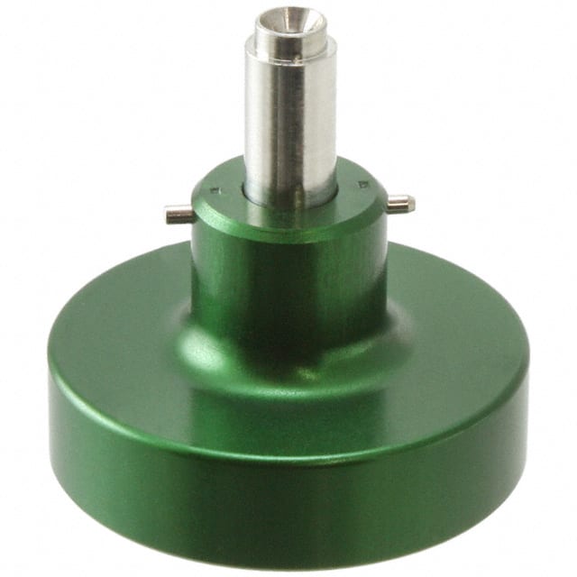
Part section showing internal components
Fixed socket
1
2
3
4
5
6
outer shell
o-ring
hexagonal nut
insulator
female contact
earthing crown
5
4
6
3
2
1
1
3
2
7
5
6
Straight plug
4
1
2
3
4
5
6
7
outer shell
insulator
male contact
rear seal
tightening screw
ratchet locking nut
spring
www.lemo.com 5
�®
®
Locking nuts options
M Series connectors offers 2 different options for coupling nut allowing to adapt ergonomics according to use cases.
The Knurled grip is the default choice for most applications as it offers a good level of grip whilst keeping a very compact
overall plug diameter.
l The Artic grip offers maximum ergonomics enabling easy manipulation even with gloves.
l
Knurled grip (standard)
Arctic grip (variant)
Backshell options
M Series connectors offers 4 different backshell options allowing for various cable assembly attachments.
The standard backshell offers a simple design allowing to either use a crimp ring or a spring for shielding attachment.
This is the default option if no specific termination is specified.
l The Mold stop offers a special geometry enabling over molding termination for a clean and rugged cable assembly finish.
l The Heat shrink molded shape offers the matching geometry to guarantee a perfect fit with heat shrink molded boots (see
page 35).
l The MIL-DTL-38999M (series III) offers the matching screw geometry allowing the use of standard D38999 compatible
backshells.
l
Mold stop
M
J
øF
T
øB
øB
J
Inner ø Y
øD
Inner ø Y
X
øF
øG
B
M
Inner ø Y
M
9
K
See page 35 for heatshrink boot
Series
P
1.5
MIL-DTL-38999M (series III)
N
øD
2
Inner ø Y
X
e
Heatshrink molded shapes
øD
Standard
N
Backshell variant dimensions (mm)
B D
e
F G J K M N P X Y Code 1)
MM
6.4 5.6
–
7.8 6.0 4.2 0.7 8.8 0.55 5.0 5.8 4.7
–
0M
8.8 8.0
–
10.7 8.4 5.1 0.7 9.7 0.60 5.8 6.7 6.6
–
1M
10.5 9.7 M12x1.0 12.4 10.1 5.1 0.7
8.3
A
2M
14.0 13.0 M15x1.0 15.5 13.4 5.1 0.7 10.1 0.80 5.8 7.1 11.6
B
3M
16.0 15.0 M18x1.0 17.5 15.4 5.1 0.7 10.1 0.80 5.8 7.1 13.6
C
TM
17.9 16.7 M18x1.0 19.8 17.1 5.2 0.8 10.6 1.00 5.8 7.6 14.6
C
4M
20.7 19.5 M22x1.0 22.6 19.9 5.2 0.8 10.6 1.00 5.8 7.6 17.6
D
LM
23.9 22.7 M25x1.0 25.8 23.1 5.2 0.8 10.6 1.00 5.8 7.6 20.6
E
5M
29.7 28.5 M31x1.0 31.4 28.9 5.2 0.8 10.6 1.00 5.8 7.6 26.6
G
9.7 0.60 5.8 6.7
Note: 1) MIL-DTL-38999M (series III) backshell connector size code (backshell not supplied) (not available in MM and 0M size).
6 www.lemo.com
�®
®
Standard models
Fll
Straight plug
FMl
P
øC
øA
øD
L
øB
Backshell
option
X
FGl
P
øC
ø A1
øD
L
øB
Backshell
option
X
Reference
Dimensions (mm)
Model Series A A1 B C D L P X
Fll MM
11.1 12.0 6.4 10.7 5.6 15.5 5.5 5.8
Fll 0M
13.1 14.4 8.8 12.7 8.0 17.4 3.9 6.7
Fll 1M
14.6 15.9 10.5 14.2 9.7 17.4 3.9 6.7
Fll 2M
17.6 18.9 14.0 17.2 13.0 17.4 3.9 7.1
Fll 3M
19.6 20.9 16.0 19.2 15.0 17.4 3.9 7.1
Fll TM
22.5 23.4 17.9 22.0 16.7 21.0 3.4 7.6
Fll 4M
25.0 25.9 20.7 24.5 19.5 21.0 3.4 7.6
Fll LM
28.5 29.4 23.9 28.0 22.7 21.0 3.4 7.6
Fll 5M
34.0 34.9 29.7 33.5 28.5 21.0 3.4 7.6
Note: B, D and X dimensions are for standard backshell. For different backshell option see page 6.
www.lemo.com 7
�®
®
Fll
Straight plug with square flange (these models are not IP68 due to the absence of panel sealing)
FXl
L
H
øD
P
øC
ø A1
øE
Backshell
option
øB
N
1.5
øA
X
øV
G
K
FWl
L
H
P
øC
ø A2
øE
Backshell
option
øD
øA
øB
N
1.5
X
øV
K
G
FAl Non-locking straight plug
L
H
øV
Note: for integration in a rackable application please contact us
for detailed informations linked to coupling constrains.
Reference
P
øC
øD
Backshell
option
øE
N
øB
øA
X
K
G
Dimensions (mm)
Model Series
A A1 A2 B C D E G H K L N P V X
Fll MM
21.5 11.1
12.0 6.4 10.7 5.6 9.5
17.0
12.0 1.5 20.3
17.0 5.5 2.7 5.8
Fll 0M
26.9
13.1
14.4 8.8 12.7 8.0
12.2
18.9
15.1 1.5 22.4
20.6 3.9 2.7 6.7
Fll 1M
31.4 14.6 15.9 10.5 14.2 9.7 13.7 18.9 18.3 1.5 22.4 23.8 3.9 3.3 6.7
Fll 2M
34.6 17.6 18.9 14.0 17.2 13.0 16.7 18.9 20.6 1.5 22.4 26.1 3.9 3.3 7.1
Fll 3M
34.6 19.6 20.9 16.0 19.2 15.0 18.7 18.9 20.6 1.5 22.4 26.1 3.9 3.3 7.1
Fll TM
38.0 22.5 23.4 17.9 22.0 16.7 21.5 22.5 23.0 2.0 27.2 28.5 3.4 3.3 7.6
Fll 4M
40.3 25.0 25.9 20.7 24.5 19.5 24.0 22.5 24.6 2.0 27.2 30.1 3.4 3.3 7.6
Fll LM
43.7 28.5 29.4 23.9 28.0 22.7 27.5 22.5 27.0 2.0 27.2 32.5 3.4 3.3 7.6
Fll 5M
47.0 34.0 34.9 29.7 33.5 28.5 33.0 22.5 29.4 2.0 27.2 37.0 3.4 3.3 7.6
Note: B, D and X dimensions are for standard backshell. For different backshell option see page 6.
8 www.lemo.com
�®
®
EGl Fixed socket, nut fixing
Ls/Lr
G
S1
P
e
øC
5.4
4.5
S2
D
E maxi
Ts/Tr
Crimp contacts
Reference
Print contacts
Dimensions (mm)
Model Series C D
e
E
G Ls Lr P S1 S2 Ts Tr
EGl MM
10.7 5.2
M7x0.5 4.5 13.8 15.0 15.0 3.7
6.3 9.0 10.7
–
EGl 0M
12.7 6.8
M9x0.6 5.0 16.8 18.3 18.3 5.3
8.2 11.0 12.4
–
9.5 13.0 12.4
EGl 1M
14.2 6.8
M11x1.0 4.5 16.8 18.3 18.3 5.3
EGl 2M
17.2 6.8
M14x1.0 4.5 16.8 18.3 18.3 5.3 12.5 17.0 12.4
–
EGl 3M
19.2 6.8
M16x1.0 4.0 16.8 18.3 18.3 5.3 14.5 19.0 12.4
–
EGl TM
22.0 9.4
M18x1.0 4.0 18.9 20.0 21.9 7.9 16.5 22.0 11.5 13.4
EGl 4M
24.5 9.4
M21x1.0 4.0 18.9 20.0 21.9 7.9 19.5 25.0 11.5 13.4
Panel cut-out (page 41).
EGl LM
28.0 9.4
M24x1.0 4.0 18.9 20.0 21.9 7.9 22.5 30.0 11.5 13.4
PCB drilling pattern (page 42).
EGl 5M
33.5 9.4
M30x1.0 4.0 18.9 20.0 21.9 7.9 28.5 36.0 11.5 13.4
Note: Ls = standard gender, Lr = reverse gender
(see page 23 for standard/reverse gender options).
–
ECl Fixed socket with two nuts (these models are not IP68 due to the absence of panel sealing)
Ls/Lr
S1
5.4
e
E maxi
S2
øA
P
øB
øC
S3
4.5
G
Crimp contacts
Reference
Print contacts
Dimensions (mm)
Model Series A
B
C E
e
G Ls Lr P S1 S2 S3
ECl MM
14.0 2.85 13.5 5.0 M10x0.50 13.8 15.0 15.0 3.7 9.0 11.0 12.0
ECl 0M
17.0 4.72 18.2 5.0 M13x0.75 16.8 18.3 18.3 5.3 11.5 14.0 16.0
ECl 1M
18.0 5.95 19.2 5.0 M14x1.00 16.8 18.3 18.3 5.3 12.5 16.0 17.0
ECl 2M
21.0 8.95 21.5 4.0 M17x1.00 16.8 18.3 18.3 5.3 15.5 18.0 19.0
ECl 3M
23.0 10.95 25.0 4.0 M19x1.00 16.8 18.3 18.3 5.3 17.5 20.0 22.0
ECl TM
27.0 12.30 28.0 2.5 M22x1.00 18.9 20.0 21.9 7.9 20.5 23.0 25.0
ECl 4M
29.0 13.95 34.0 2.5 M24x1.00 18.9 20.0 21.9 7.9 22.5 25.0 30.0
Panel cut-out (page 41).
ECl LM
33.0 17.95 36.0 2.5 M28x1.00 18.9 20.0 21.9 7.9 26.5 29.0 32.0
PCB drilling pattern (page 42).
ECl 5M
38.0 22.90 41.0 2.5 M33x1.00 18.9 20.0 21.9 7.9 31.5 34.0 37.0
Note: Ls = standard gender, Lr = reverse gender
(see page 23 for standard/reverse gender options).
www.lemo.com 9
�®
®
EDl Fixed socket with square flange
Ls/Lr
K
P
H
5.4
øC
øA
øB
N
4.5
øV
Ts/Tr
G
Crimp contacts
Print contacts
Dimensions (mm)
Reference
Model Series A
B
C G H K Ls Lr N P Ts Tr V
EDl MM
18.6 4.70 10.7 13.8 9.5 1.5 17.0 17.0 14.5 3.7 4.1
–
2.7
EDl 0M
20.6 4.72 12.7 14.3 11.0 1.5 18.3 18.3 16.0 5.3 4.9
–
2.7
EDl 1M
23.8 5.95 14.2 14.3 12.9 1.5 18.3 18.3 18.4 5.3 4.9
–
3.3
EDl 2M
26.9 8.95 17.2 14.3 15.1 1.5 18.3 18.3 20.6 5.3 4.9
–
3.3
EDl 3M
29.0 10.95 19.2 14.3 16.6 1.5 18.3 18.3 22.1 5.3 4.9
–
3.3
EDl TM
31.4 12.30 22.0 16.5 18.3 2.0 20.0 21.9 23.8 7.9 4.4
6.3 3.3
EDl 4M
34.6 13.95 24.5 16.5 20.6 2.0 20.0 21.9 26.1 7.9 4.4
6.3 3.3
Panel cut-out (page 41).
EDl LM
38.0 17.95 28.0 16.5 23.0 2.0 20.0 21.9 28.5 7.9 4.4
6.3 3.3
PCB drilling pattern (page 42).
EDl 5M
43.7 22.90 33.5 16.5 27.0 2.0 20.0 21.9 32.5 7.9 4.4
6.3 3.3
Note: Ls = standard gender, Lr = reverse gender
(see page 23 for standard/reverse gender options).
PEl Fixed socket, nut fixing (back panel mounting)
Ls/Lr
S1
e
øA
øB
P
øF
øC
øD
M
Backshell
option
X
1.5
S2
E maxi
R
Reference
Dimensions (mm)
Model Series A B C D E
F
e
Ls Lr Ls1) Lr1) M P R S1 S2 X
PEl MM
14.0 6.4 13.8 5.6 4.0 7.8 M10x0.50 12.6 12.6 –
– 8.8 3.7 10.5 9.0 11.0 5.8
PEl 0M
17.0 8.8 16.8 8.0 5.0 10.7 M13x0.75 15.9 15.9 –
– 9.7 5.3 13.8 11.5 14.0 6.7
PEl 1M
18.0 10.5 17.8 9.7 5.0 12.4 M14x1.00 15.9 15.9 17.4 17.4 9.7 5.3 13.8 12.5 16.0 6.7
PEl 2M
21.0 14.0 20.8 13.0 5.0 15.5 M17x1.00 15.9 15.9 17.4 17.4 10.1 5.3 13.8 15.5 18.0 7.1
PEl 3M
23.0 16.0 22.8 15.0 5.0 17.5 M19x1.00 15.9 15.9 17.4 17.4 10.1 5.3 13.8 17.5 20.0 7.1
PEl TM
27.0 17.9 25.8 16.7 4.0 19.8 M22x1.00 18.9 19.5 19.2 21.1 10.6 7.9 16.9 20.5 23.0 7.6
PEl 4M
29.0 20.7 27.8 19.5 4.0 22.6 M24x1.00 18.9 19.5 19.2 21.1 10.6 7.9 16.9 22.5 25.0 7.6
PEl LM
33.0 23.9 31.8 22.7 4.0 25.8 M28x1.00 18.9 19.5 19.2 21.1 10.6 7.9 16.9 26.5 29.0 7.6
PEl 5M
38.0 29.7 36.8 28.5 4.0 31.4 M33x1.00 18.9 19.5 19.2 21.1 10.6 7.9 16.9 31.5 34.0 7.6
Panel cut-out
(page 41).
Note: Ls = standard gender, Lr = reverse gender (see page 23 for standard/reverse gender options).
This model is not available with standard backshell option (backshell not supplied). For different backshell option see page 6.
1) Dimensions for MIL-DTL-38999M (series III) backshell connector size code (backshell not supplied) (not available in MM and 0M size).
10 www.lemo.com
�®
®
Fixed socket with square flange (these models are not IP68 due to the absence of panel sealing)
M
G
1.5
P
øC
Backshell
option
øD
øA
øF
øE
N
øB
PFl
H
øV
X
K
Ls/Lr
Reference
Dimensions (mm)
Model Series
A B C D E F G H K Ls Lr
Ls1) Lr1) M N P V X
PFl MM
18.6 6.4 10.7 5.6 7.8 7.8 12.3 9.5 1.5 15.6 15.6 –
–
8.8 14.5 3.7 2.7 5.8
PFl 0M
20.6 8.8 12.7 8.0 10.7 10.7 12.8 11.0 1.5 15.9 15.9
–
9.7 16.0 5.3 2.7 6.7
PFl 1M
23.8 10.5 14.2 9.7 12.4 12.4 12.8 12.9 1.5 15.9 15.9 17.5 17.5 9.7 18.4 5.3 3.3 6.7
PFl 2M
26.9 14.0 17.2 13.0 15.5 15.5 12.8 15.1 1.5 15.9 15.9 17.5 17.5 10.1 20.6 5.3 3.3 7.1
PFl 3M
29.0 16.0 19.2 15.0 17.5 17.5 12.8 16.6 1.5 15.9 15.9 17.5 17.5 10.1 22.1 5.3 3.3 7.1
PFl TM
31.4 17.9 22.0 16.7 19.8 19.8 14.5 18.3 2.0 18.9 19.5 19.2 21.1 10.6 23.8 7.9 3.3 7.6
PFl 4M
34.6 20.7 24.5 19.5 22.6 22.6 14.5 20.6 2.0 18.9 19.5 19.2 21.1 10.6 26.1 7.9 3.3 7.6
PFl LM
38.0 23.9 28.0 22.7 25.8 25.8 14.5 23.0 2.0 18.9 19.5 19.2 21.1 10.6 28.5 7.9 3.3 7.6
PFl 5M
47.0 29.7 33.5 28.5 33.0 31.4 14.5 29.4 2.0 18.9 19.5 19.2 21.1 10.6 37.0 7.9 3.3 7.6
–
Panel cut-out
(page 41).
Note: Ls = standard gender, Lr = reverse gender (see page 23 for standard/reverse gender options).
This model is not available with standard backshell variant (backshell not supplied). For different backshell option see page 6.
1) Dimensions for MIL-DTL-38999M (series III) backshell connector size code (backshell not supplied) (not available in MM and 0M size).
www.lemo.com 11
�®
®
Free socket
PMl
PHl
Ls/Lr
øD
øC
øA
øC
P
øB
Backshell
option
øD
X
Reference
Ls/Lr
P
øB
Backshell
option
ø A1
Pll
X
Dimensions (mm)
Model Series A A1 B C D Ls Lr Ls1) Lr1) Ls2) Lr2) P X
Pll MM
11.1 12.0 6.4 10.7 5.6 15.6 15.6 15.6 15.6 –
– 3.7 5.8
Pll 0M
13.1 14.4 8.8 12.7 8.0 18.9 18.9 18.9 18.9 –
– 5.3 6.7
Pll 1M
14.6 15.9 10.5 14.2 9.7 18.9 18.9 18.9 18.9 18.9 18.9 5.3 6.7
Pll 2M
17.6 18.9 14.0 17.2 13.0 18.9 18.9 18.9 18.9 18.9 18.9 5.3 7.1
Pll 3M
19.6 20.9 16.0 19.2 15.0 18.9 18.9 18.9 18.9 18.9 18.9 5.3 7.1
Pll TM
22.5 23.4 17.9 22.0 16.7 20.6 22.5 20.6 20.6 20.6 21.1 7.9 7.6
Pll 4M
25.0 25.9 20.7 24.5 19.5 20.6 22.5 20.6 20.6 20.6 21.1 7.9 7.6
Pll LM
28.5 29.4 23.9 28.0 22.7 20.6 22.5 20.6 20.6 20.6 21.1 7.9 7.6
Pll 5M
34.0 34.9 29.7 33.5 28.5 20.6 22.5 20.6 20.6 20.6 21.1 7.9 7.6
Note: Ls = standard gender, Lr = reverse gender (see page 23 for standard/reverse gender options).
B, D and X dimensions are for standard backshell. For different backshell option see page 6.
1) Dimensions for mold stop and heatshrink molded shapes backshell option.
2) Dimensions for MIL-DTL-38999M (series III) backshell connector size code (backshell not supplied) (not available in MM and 0M size).
12 www.lemo.com
�®
®
Pll
Fixed socket with antivibration flange (these models are not IP68 due to the absence of panel sealing)
PBl
Ls/Lr
P
K
øC
B1
øB
H
Backshell
option
øD
N
X
2.7 (MM)
3.3 (0M-5M)
G
PVl
Ls/Lr
øA
P
øC
Backshell
option
øD
K
øB
øC
N1
X
H1
ø 2.7 (MM-0M)
ø 3.3 (1M-5M)
G
PTl
Ls/Lr
øA
Backshell
option
P
øD
K1
øB
øC
øC
N1
X
H1
Reference
M2.5 (MM-0M)
M3.0 (1M-5M)
G1
Dimensions (mm)
Model Series
A B B1 C D G G1 H H1 K K1 N N1 P Ls Lr Ls1) Lr1) Ls2) Lr2) X
Pll MM
21.5 6.4 21.0 11.3 5.6 6.7 6.0 16.2 12.0 1.5 3.0 12.5 17.0 3.7 15.6 15.6 15.6 15.6 –
– 5.8
Pll 0M
26.9 8.8 27.0 14.5 8.0 8.3 7.3 21.4 15.1 2.0 4.0 16.0 20.6 5.3 18.9 18.9 18.9 18.9 –
– 6.7
Pll 1M
31.4 10.5 29.0 16.5 9.7 8.3 7.3 23.4 18.3 2.0 4.0 18.0 23.8 5.3 18.9 18.9 18.9 18.9 18.5 18.5 6.7
Pll 2M
34.6 14.0 32.0 19.5 13.0 8.3 7.3 26.4 20.6 2.0 4.0 21.0 26.1 5.3 18.9 18.9 18.9 18.9 18.5 18.5 7.1
Pll 3M
38.0 16.0 35.0 21.5 15.0 8.3 7.3 29.0 23.0 2.0 4.0 23.0 28.5 5.3 18.9 18.9 18.9 18.9 18.5 18.5 7.1
Pll TM
40.3 17.9 38.5 24.5 16.7 11.0 10.0 32.5 24.6 2.0 4.0 26.0 30.1 7.9 20.6 22.5 20.6 20.6 20.2 21.1 7.6
Pll 4M
43.7 20.7 41.0 27.5 19.5 11.0 10.0 35.0 27.0 2.0 4.0 29.0 32.5 7.9 20.6 22.5 20.6 20.6 20.2 21.1 7.6
Pll LM
47.1 23.9 44.0 30.5 22.7 11.0 10.0 38.0 29.4 2.0 4.0 32.0 34.9 7.9 20.6 22.5 20.6 20.6 20.2 21.1 7.6
Pll 5M
54.9 29.7 51.0 37.5 28.5 11.0 10.0 45.0 34.9 2.0 4.0 39.0 40.4 7.9 20.6 22.5 20.6 20.6 20.2 21.1 7.6
Note: Ls = standard gender, Lr = reverse gender (see page 23 for standard/reverse gender options).
B, D and X dimensions are for standard backshell. For different backshell option see page 6.
1) Dimensions for mold stop and heatshrink molded shapes backshell option.
2) Dimensions for MIL-DTL-38999M (series III) backshell connector size code (backshell not supplied) (not available in MM and 0M size).
Panel cut-out (page 41).
www.lemo.com 13
�®
®
Watertight model (unmated)
H E
Part numbering system
Fixed socket
3 0 5 . X L N P
H E N . 1 M .
Model: HE
Alignment key: (page 23)
Series: (see below)
Potting: P = Epoxy
Insert configuration: (page 24)
Contact: (page 30)
Housing:
C = Chrome-plated brass
X = Nickel-plated aluminium alloy 1)
Insulator:
L = PEEK (multipole page 24)
R = PEEK (mixed multipole p. 26)
HEN.1M.305.XLNP = fixed socket, nut fixing, with key (N), 1M series, multipole type with 5 contacts, outer shell in anthracite nickel-plated
aluminium alloy, PEEK insulator, female print contacts, watertight.
Note: 1) anthracite colour / 48 hours salt fog resistance.
Environmental performance
Characteristics
Operating temperature
Value
Standard
-20°C/+80°C –
Value
Characteristics
Unmated ingress protection
IP68 (at 2 m, 15 Hr)
Standard
IEC 60529
HEl Fixed socket, nut fixing, key (N) or keys (H, P, R, S, T, U, V, W and X), for printed circuit,
watertight (back panel mounting)
Ls/Lr
P
e
H
øA
S1
øC
0.8
E maxi
S2
R
N
Reference
Dimensions (mm)
Model Series
A C
e
E H Ls Lr N P R S1
S2
HEl MM
14.0 13.8 M10x0.50 4.0 5.08 20.4 20.4 15.3 3.7 10.5 9.0 11.0
HEl 0M
17.0 16.8 M13x0.75 5.0 5.08 20.8 21.0 16.8 5.3 13.8 11.5 14.0
HEl 1M
18.0 17.8 M14x1.00 5.0 7.62 20.8 21.0 16.8 5.3 13.8 12.5 16.0
HEl 2M
21.0 20.8 M17x1.00 5.0 8.89 20.8 21.0 16.8 5.3 13.8 15.5 18.0
HEl 3M
23.0 22.8 M19x1.00 5.0 10.16 20.8 21.0 16.8 5.3 13.8 17.5 20.0
HEl TM
27.0 25.8 M22x1.00 4.0 12.70 24.6 24.6 19.9 7.9 16.9 20.5 23.0
Panel cut-out (page 41).
HEl 4M
29.0 27.8 M24x1.00 4.0 13.97 24.6 24.6 19.9 7.9 16.9 22.5 25.0
PCB drilling pattern (page 42).
HEl LM
33.0 31.8 M28x1.00 4.0 16.51 24.6 24.6 19.9 7.9 16.9 26.5 29.0
HEl 5M
38.0 36.8 M33x1.00 4.0 20.32 24.6 24.6 19.9 7.9 16.9 31.5 34.0
Note: in MM series, the four external earth
contacts are shorter.
Ls = standard gender, Lr = reverse gender
(see page 23 for standard/reverse gender options).
14 www.lemo.com
�®
®
Vacuumtight model (unmated)
H Y
Part numbering system
Fixed socket
3 0 5 . X L H W G E
H Y N . 1 M .
O-ring material: E = EPDM
PCB fixation:
G = 4 ground pins
Z = 4 threaded holes
Model: HY
Series: (see below)
Potting:
R = Silicone
W = Silicone 100% vacuum tested
Insert configuration: (page 24)
Contact:
H = female/male print (page 30)
Housing:
C = Chrome-plated brass
X = Nickel-plated aluminium alloy 1)
Insulator:
L = PEEK (multipole page 24)
R = PEEK (mixed multipole p. 26)
Alignment key: (page 23)
HYN.1M.305.XLHWGE = fixed socket, nut fixing, with key (N), 1M series, multipole type with 5 contacts, outer shell in anthracite
nickel-plated aluminium alloy, PEEK insulator, female print contacts, vacuumtight, with 4 ground pins and a EPDM o-ring.
Note: 1) anthracite colour / 48 hours salt fog resistance.
Environmental performance
Characteristics
Operating temperature
Value
Value
Characteristics
Standard
-55°C/+150°C –
< 10-7 mbar.l.s-1
Leakage rate
Standard
IEC 60512-7 test 14 b
HYl Fixed socket, nut fixing, key (N) or keys (H, P, R, S, T, U, V, W and X), for printed circuit,
vacuumtight (back panel mounting)
L
H
Detail A
J
e
E maxi
øF
S1
øA
1
øC
3
øV
S2
R
N
Reference
PCB fixation (Detail A)
Dimensions (mm)
Model Series A C
e
E
F
H
J
L N R S1 S2
V
14.0 13.8 M10x0.50 4.0
5.7 6.35 3.0 19.1 16.1 10.5 9.0 11.0 M2x0.4
HYl 0M
17.0 16.8 M13x0.75 5.3
7.8 8.89 5.0 22.4 19.4 13.8 11.5 14.0 M2x0.4
HYl 1M
18.0 17.8 M14x1.00 5.3
8.8 10.16 5.5 22.4 19.4 13.8 12.5 16.0 M2x0.4
HYl 2M
21.0 20.8 M17x1.00 5.3 11.8 11.43 7.0 22.4 19.4 13.8 15.5 18.0 M2x0.4
HYl 3M
23.0 22.8 M19x1.00 5.3 13.8 12.70 8.0 22.4 19.4 13.8 17.5 20.0 M2x0.4
HYl TM
27.0 25.8 M22x1.00 4.5 15.2 13.97 8.7 26.0 23.0 17.4 20.5 23.0 M3x0.5
HYl 4M
29.0 27.8 M24x1.00 4.5 16.8 15.24 9.5 26.0 23.0 17.4 22.5 25.0 M3x0.5
HYl LM
33.0 31.8 M28x1.00 4.5 20.8 17.78 11.5 26.0 23.0 17.4 26.5 29.0 M3x0.5
HYl 5M
38.0 36.8 M33x1.00 4.5 25.9 21.59 14.0 26.0 23.0 17.4 31.5 34.0 M3x0.5
Z
3.5
3.8
0.9
V
HYl MM
G
Panel cut-out (page 41).
PCB drilling pattern (page 44).
Note: special anti-vibration thread
to be used with standard metric screws
(not supplied).
www.lemo.com 15
�®
®
2 M 5 1 4
High Speed models
Those configurations meet the Ethernet 10Gb/s data transfer requirements (CAT6, up to 250 MHz).
Part numbering system
Plug
5 1 4 . X L C T 6
F M N . 2 M .
Free socket
5 1 4 . X L M T 6
P M N . 2 M .
Fixed socket
5 1 4 . X L N P
H E N . 2 M .
Model: (page 16)
Alignment key: (page 23)
Series: 2M
Maximum cable outer ø:
6, 7 and 8 (mm)
Insert configuration: 514 (page 26)
T = Mold stop
P = Potted (HEl model only)
Housing:
X = Nickel-plated aluminium alloy 1)
I = NiCorAITM Nickel
fluorocarbon polymer
aluminium alloy 2)
Contact: crimp or print (page 30)
Insulator: L = PEEK
FMN.2M.514.XLCT6 = straight plug with key (N), knurled grip, 2M series, multipole type with 8 contacts, outer shell in anthracite
nickel-plated aluminium alloy, PEEK insulator, male crimp contacts.
PMN.2M.514.XLMT6 = free socket with key (N), knurled grip, 2M series, multipole type with 8 contacts, outer shell in anthracite
nickel-plated aluminium alloy, PEEK insulator, female crimp contacts and mold stop.
HEN.2M.514.XLNP = fixed socket, nut fixing, with key (N), 2M series, multipole type with 8 contacts, outer shell in anthracite nickel-plated
aluminium alloy, PEEK insulator, female print contacts, watertight.
Note: 1) anthracite colour / 48 hours salt fog resistance. 2) anthracite colour / 500 hours salt fog resistance RoHS 2/REACH.
FMl.2M.514 Straight plug, key (N) or keys (P and U) with knurled grip and mold stop
30
ø 17.2
ø 17.6
ø 13
0.5
ø 18.9
3.9
ø 17.2
12.6
ø 14
ø 15.5
Inner ø 11.6
1.5
9.6
FGl.2M.514 Straight plug, key (N) or keys (P and U) with arctic grip and mold stop
30
12.6
3.9
0.5
ø 13
ø 14
ø 15.5
Inner ø 11.6
1.5
9.6
16 www.lemo.com
� 2 M 5 1 4
®
®
PEl.2M.514 Fixed socket, key (N) or keys (P and U) with mold stop (back panel mounting)
31.5
5.3
12.6
S 18
5 maxi
ø 13
0.5
Inner ø 11.6
ø 21
M17x1
15.6
ø 14
ø 15.5
ø 20.8
S 15.5
13.8
1.5
PFl.2M.514 Fixed socket with square flange, key (N) or keys (P and U) with mold stop
Note: (this model is not IP68 due to the absence of panel sealing)
12.8
1.5
5.3
Inner ø 11.6
0.5
15.1
ø 13
ø 14
ø 17.2
15.6
ø 15.5
ø 3.3
17.2
ø 26.9
20.6
1.5
12.6
PMl.2M.514 Free socket, key (N) or keys (P and U) with knurled grip and mold stop
31.5
ø 13
0.5
ø 17.6
ø 14
ø 15.5
5.3
ø 17.2
12.6
Inner ø 11.6
1.5
9.6
PHl.2M.514 Free socket, key (N) or keys (P and U) with arctic grip and mold stop
ø 13
0.5
ø 18.9
ø 17.2
5.3
ø 14
ø 15.5
31.5
12.6
Inner ø 11.6
1.5
9.6
HEl.2M.514 Fixed socket, nut fixing, key (N) or keys (P and U), printed circuit, watertight, (back panel mounting)
21
5.3
8.89
ø 20.8
ø 21
S 15.5
M17x1
0.8
5 maxi
S 18
13.8
16.8
Note: see page 41 for panel cut-out and page 42 for PCB drilling pattern. For HEl environmental performance see page 14.
www.lemo.com 17
�®
®
L M U 2 A
USB 2.0 models
Those configurations meet the USB 2.0 (480 Mb/s) data transfer requirements using USB Type A inserts.
FMl.LM.U2A.XPAT Straight plug, key (W) or keys (R and H) with knurled grip and mold stop
31.6
ø 28
ø 28.5
ø 28
ø 29.4
ø 22.7
ø 25.8
3.4
ø 23.9
10.6
1.5
7.6
FGl.LM.U2A.XPAT Straight plug, key (W) or keys (R and H) with arctic grip and mold stop
31.6
ø 22.7
ø 25.8
3.4
ø 23.9
10.6
1.5
7.6
EGl.LM.U2A.XPP
Fixed socket, female to female, nut fixing, key (W) or keys (R and H)
40.5
7.9
ø 28
M 24 x 1
S 22.5
S 30
4 maxi
9.4
31
EGl.LM.U2A.XPL
Fixed socket, nut fixing, key (W) or keys (R and H)
18.9
7.9
S 30
ø 28
M 24 x 1
S 22.5
4 maxi
9.4
Note: see page 41 for panel cut-out.
18 www.lemo.com
�®
®
Fibre Optic models
Fll
Straight plug (contact to be ordered separately, see page 31)
FMl
L
øA
øC
P
S2
FGl
S1
L
S2
Part number
S1
Dimensions (mm)
A A1 C
L
P S1 S2
FlS.2M.03A.XLZTllZ
17.6 18.9 17.2 100.6 3.9 14.0 14.0
FlN.3M.95B.XLCTllZ
19.6 20.9 19.2 103.3 3.9 16.0 16.0
FlW.5M.03W.XLZTllZ
34.0 34.9 33.5 148.4 3.4 29.0 29.0
Pll
øC
ø A1
P
Note: ll cable adaptor diameter defined upon request.
The bend relief must be ordered separately (see page 37).
Free socket (contact to be ordered separately, see page 31)
PMl
L
øA
øC
P
S2
PHl
S1
L
øA
øC
P
S2
Part number
S1
Dimensions (mm)
A A1 C
L
P S1 S2
PlS.2M.03A.XLZTllZ
17.6 18.9 17.2 105.8 5.3 16.0 14.0
PlN.3M.95B.XLMTllZ
19.6 20.9 19.2 113.3 5.3 18.0 16.0
PlW.5M.03W.XLZTllZ
34.0 34.9 33.5 155.2 7.9 32.0 29.0
Note: ll cable adaptor diameter defined upon request.
The bend relief must be ordered separately (see page 37).
www.lemo.com 19
�®
®
EGl Fixed socket, nut fixing (contact to be ordered separately, see page 31)
Part number
L
S1
e
øC
P
S2
D
E maxi
Dimensions (mm)
C D
e
E L P S1 S2
EGS.2M.03A.XLZ
17.2 6.8 M14x1.0 4.5 28.9 5.3 12.5 17.0
EGN.3M.95B.XLM
19.2 6.8 M16x1.0 4.0 32.2 5.3 14.5 19.0
EGW.5M.03W.XLZ
33.5 9.4 M30x1.0 4.0 30.8 7.9 28.5 36.0
Panel cut-out (page 41).
EDl Fixed socket with square flange (contact to be ordered separately, see page 31)
Part number
L
P
øC
K
øA
øB
N
Dimensions (mm)
A B C G H K L N P
EDS.2M.03A.XLZ
26.9 8.95 17.2 12.8 15.1 1.5 28.9 20.6 5.3
EDN.3M.95B.XLM
29.0 10.95 19.2 12.8 16.6 1.5 32.2 22.1 5.3
EDW.5M.03W.XLZ
43.7 22.90 33.5 14.5 27.0 2.0 30.8 32.5 7.9
Panel cut-out (page 41).
H
ø 3.3
G
20 www.lemo.com
�®
®
High Power models
Part numbering system
Plug
Free socket
Fixed socket
F G S . 3 M . H 1 4 . X L M
P H S . 3 M . H 1 4 . X L C M
P E S . 3 M . H 1 4 . X L C T H
Model: (page 21)
Variant:
H = Watertight (PEl model only)
Alignment key: (page 23)
S, T, X or V (reverse gender only)
Backshell options: (page 6)
Blank = standard
B = Ruggedized for heatshrink
molded shapes
T = Mold stop
M = MIL-DTL-38999L shell thread
Series: (page 21)
Insert configuration: (page 28)
Housing:
C = Chrome-plated brass
X = Nickel-plated aluminium alloy 1)
I = NiCorAITM Nickel
fluorocarbon polymer
aluminium alloy 2)
Contact: (reverse gender only)
C = Male to crimp
M = Female to crimp
Insulator: L = PEEK
FGS.3M.H14.XLM = straight plug with key (S), knurled grip, 3M series, high power contacts, outer shell in anthracite nickel-plated aluminium alloy, PEEK insulator, female crimp contacts.
PHS.3M.H14.XLCM = free socket with key (S), knurled grip, 3M series, high power contacts, outer shell in anthracite nickel-plated aluminium alloy, PEEK insulator, male crimp contacts, MIL-DTL-38999L shell thread.
PES.3M.H14.XLCTH = fixed socket with key (S), 3M series, high power contacts, outer shell in anthracite nickel-plated aluminium alloy,
PEEK insulator, male crimp contacts, mold stop, watertight.
Note: 1) anthracite colour / 48 hours salt fog resistance. 2) anthracite colour / 500 hours salt fog resistance RoHS 2/REACH.
FMl / FGl Straight plug
FXl / FWl / FAl Straight plug with square flange
U
øB
øB
U
Reference
øB
(mm)
Dimensions U (mm)
Backshell options
Standard
Code B / T
Code M
Reference
øB
(mm)
Dimensions U (mm)
Backshell options
Standard
Code B / T
Code M
3M.H14
11.0
5.5
2.5
3.6
3M.H14
11.0
0.5
–
–
TM.H15
12.3
5.5
2.5
4.1
TM.H15
12.3
–
–
–
4M.H16
14.0
5.5
2.5
4.1
4M.H16
14.0
–
–
–
LM.H18
18.0
10.0
7.0
8.6
LM.H18
18.0
3.8
0.8
2.4
5M.H18
22.9
10.0
7.0
8.6
5M.H18
22.9
3.8
0.8
2.4
–
–
–
–
–
–
5M.H34 / G33 22.9
Note: all others dimensions can be found on standard models (page 7).
5M.H34 / G33 22.9
Note: all others dimensions can be found on standard models (page 8).
www.lemo.com 21
�®
EGl / ECl Fixed socket
EDl Fixed socket
Reference
øB
U
Dim. (mm)
ø B
Reference
U
3M.H14
11.0 11.7
TM.H15
12.3 13.1
4M.H16
14.0 13.1
LM.H18
5M.H18
U
Dim. (mm)
ø B
U
3M.H14
11.0 14.2
TM.H15
12.3 15.5
4M.H16
14.0 15.5
18.0 17.6
LM.H18
18.0 20.0
22.9 17.6
5M.H18
22.9 20.0
øB
®
5M.H34 / G33 22.9 10.6
5M.H34 / G33 22.9 13.0
Note: all others dimensions can be found on standard models (page 9).
Note: all others dimensions can be found on standard models (page 10).
PEl / PFl Fixed socket
PMl / PHl Free socket
U
Reference
øB
(mm)
øB
øB
U
Dimensions U (mm)
Backshell options
Code B / T
Code M
Reference
øB
(mm)
Dimensions U (mm)
Backshell options
Standard
Code B / T
Code M
3M.H14
11.0
2.5
2.1
3M.H14
11.0
2.5
–
0.6
TM.H15
12.3
1.9
1.9
TM.H15
12.3
1.9
0.8
1.9
4M.H16
14.0
1.9
1.9
4M.H16
14.0
1.9
0.8
1.9
LM.H18
18.0
6.4
6.4
LM.H18
18.0
6.4
5.3
6.4
5M.H18
22.9
6.4
6.4
5M.H18
22.9
6.4
5.3
6.4
–
–
–
–
–
5M.H34 / G33 22.9
5M.H34 / G33 22.9
Note: all others dimensions can be found on standard models (p. 10, 11).
Note: all others dimensions can be found on standard models (p. 12).
PBl / PVl / PTl Fixed socket with antivibration flange
øB
U
Reference
øB
(mm)
Dimensions U (mm)
Backshell options
Standard
Code B / T
Code M
3M.H14
11.0
2.5
–
1.0
TM.H15
12.3
1.9
0.8
1.9
4M.H16
14.0
1.9
0.8
1.9
LM.H18
18.0
6.4
5.3
6.4
5M.H18
22.9
6.4
5.3
6.4
–
–
–
5M.H34 / G33 22.9
Note: all others dimensions can be found on standard models (p. 13).
22 www.lemo.com
�®
®
Alignment key
Alignment key and Polarized keying system
MM to 3M
Front view of a socket
Model
M series connector model part numbers are composed of three letters. The LAST LETTER indicates the keys corresponding
to a particular contact type.
For example, straight plugs with H, N, P, R, U or W keys, are fitted with male contacts; whereas with S, T, V or X keys,
plugs are fitted with female contacts. Sockets with H, N, P, R, U or W keys, are fitted with female contacts; whereas with
S, T, V or X keys, sockets are fitted with male contacts.
ll
β
N
blue
P
yellow
U
green
ll
S
red
T
orange
Model
ll
Colour
code
ll
γ
ll
α
β
W
blue
ll
R
yellow
ll
H
green
ll
δ
γ
TM to 5M
Front view of a socket
Colour
code
ll
X
red
ll
V
orange
Contact type
Gender
Plug
Socket
standard male
female
reverse female
male
Contact type
Gender
Plug
standard male
Socket
female
Angles
Nb
of
keys
3
3
β
γ
165°
30°
150°
60°
130°
100°
155°
50°
135°
90°
Nb
of
keys
5
Angles
α
β
γ
δ
95°
115°
35°
25°
105°
115°
30°
20°
120° 95° 25° 45°
reverse female
male
5
100°
125°
40°
20°
110°
120°
35°
25°
Colour coding
M Series connector attributes a colour code for each alignment key thus allowing for easy identification of matching plugs
and sockets within the system.
l
l
Standard plated versions only have a light colour ring on the plug nut and socket for identification.
Anodized aluminum version are proposed with the complete body matching the corresponding colour code / key.
Colour code
Standard nickel-plated aluminium version
Anodized aluminium version
www.lemo.com 23
�®
®
Insert configuration
Contact
type
1M
2M
3M
2
303
3
0.5 l
l 28-30-32 1.15 0.95 3.0
304
4
0.5 l
l 28-30-32 0.95 0.90 2.0
302
303
3
0.9 l
l 20-22-24 1.70 1.40 8.0
304
4
0.7 l
l 22-24-26 1.35 0.90 7.0
305
5
0.7 l
l 22-24-26 1.25 1.00 6.5
302
2 1.3 l
l 16-18-20 1.55 1.10 19.0
303
3
1.3 l
l 16-18-20 1.05 0.95 15.5
305
5
0.9 l
l 20-22-24 1.30 1.30 9.0
307
7
0.7 l
l 22-24-26 1.45 1.20 7.0
308
8
0.7 l
l 22-24-26 1.30 1.10 5.0
304
4
1.3 l
l 16-18-20 1.55 1.35 15.5
308
8
0.9 l
l 20-22-24 1.95 1.10 10.0
310
10
0.9
l
l 20-22-24 1.80 1.20 8.0
312
12
0.7
l
l 22-24-26 1.65 1.15 7.0
316
16
0.7
l
l 22-24-26 1.20 1.00 4.5
319
19
0.7
l
l 22-24-26 1.20 1.00 4.0
312
12
0.9
l
l 20-22-24 1.40 1.25 6.0
322
22
0.7
l
l 22-24-26 1.25 1.15 4.0
330
30
0.7
l
l 22-24-26 1.10 1.00 3.5
2 0.9 l
Rated current (A)2)
3
AWG
3
Print (straight)3)
2
Crimp
1
ø A (mm)
4
Number of contacts
0M
4
Reference
MM
1
Test voltage (kV rms)1)
Contact-shell
Female insert
øA
Male insert
Test voltage (kV rms)1)
Contact-contact
Multipole
l 20-22-24 1.45 1.00 10.0
24 www.lemo.com
�®
®
Contact
type
25
0.9
l
l 20-22-24 1.10 1.25 5.0
332
32
0.7
l
l 22-24-26 1.25 1.20 3.5
340
40
0.7
l
l 22-24-26 1.05 1.20 3.0
340
40 0.7 l
l 22-24-26 1.20 1.35 3.5
348
48
l
l 22-24-26 1.10 1.35 3.0
355
55 0.9 l
l 20-22-24 1.65 1.95 3.5
368
68
l
l 22-24-26 1.40 1.65 2.5
366
66 0.9 l
l 20-22-24 1.60 1.70 3.0
114
114
l 22-24-26 1.37 1.34 2.0
0.7
0.7
0.7
l
Rated current (A)2)
325
AWG
Print (straight)3)
2
Crimp
5M
1
3
ø A (mm)
LM
4
3
Number of contacts
4M
4
2
Reference
TM
1
Test voltage (kV rms)1)
Contact-shell
Female insert
øA
Male insert
Test voltage (kV rms)1)
Contact-contact
Multipole
Note:
1) test voltage according to IEC 60512-2 test 4a. Altitude correction factor is given in IEC 60664-1 table A.2.
2) the specified rated current can be applied simultaneously to all the contacts. It corresponds to an average temperature rise of 40°C of the connector
(measured according to IEC 60512-3 test 5a).
3) for EG•, EC•, ED•, HE•, HY• socket.
www.lemo.com 25
�®
®
Rated current (A)2)
AWG
2
Crimp
1
3
ø A (mm)
4
3
Number of contacts
4
2
Reference
1
Print (straight)3)
Contact
type
Test voltage (kV rms)1)
Contact-shell
Female insert
øA
Male insert
Test voltage (kV rms)1)
Contact-contact
Mixed multipole
1M
304
2 0.7
22-24-26 1.20 1.30 11.0
l
l
2 1.3
16-18-20 1.45 2.00 18.5
2M
306
3 0.7
22-24-26 1.55 1.40 10.5
l
l
3 1.3
16-18-20 2.05 1.35 18.0
308
6 0.7
22-24-26 1.95 1.40 7.0
l
l
2 1.3
16-18-20 1.75 1.60 23.0
310
8 0.7
22-24-26 1.35 1.35 6.0
l
l
2 1.3
16-18-20 1.90 1.15 23.0
316
10
0.7
22-24-26 0.90 0.95 2.0
l
l
6 1.3
16-18-20 1.35 1.15 11.0
366
44
0.7
l
l 22-24-26
22 1.3 4)
3M
5M
1.65 2.70 3.0
1.95 1.80 6.0
Note:
1) test voltage according to IEC 60512-2 test 4a. Altitude correction factor is given in IEC 60664-1 table A.2.
2) the specified rated current can be applied simultaneously to all the contacts. It corresponds to an average temperature rise of 40°C of the connector
(measured according to IEC 60512-3 test 5a).
3) for EG•, EC•, ED•, HE•, HY• socket.
4) reduced crimp barrel.
Multipole high speed ethernet cat6
2M
2
3
4
1
8
5
7
6
7
1
8
6
5
2
4
3
514
8 0.7 l
Rated current (A)2)
rms)1)
Test voltage (kV
Contact-shell
2
Crimp contact
1
3
ø A (mm)
4
3
Number of contacts
4
2
Reference
1
Test voltage (kV rms)1)
Contact-contact
Female insert
øA
Male insert
1.5 1.5 8
Note:
1) test voltage according to IEC 60512-2 test
2) the specified rated current can be applied
4a. Altitude correction factor is given in IEC 60664-1 table A.2.
simultaneously to all the contacts. It corresponds to an average temperature rise of 40°C of the connector
(measured according to IEC 60512-3 test 5a).
26 www.lemo.com
�®
®
4
l
1.20 0.95 n.a.
Rated current (A)2)
Test voltage (kV rms)1)
Contact-contact
Test voltage (kV rms)1)
Contact-shell
Solder contact
Female insert
front view
Reference
Male insert
front view
Number of contacts
USB 2.0
LM
U2A
Note: 1) and 2) see page 26. See models on page 18.
Multi fibre and Mixed fibre optic + low voltage
Low voltage contact
2
–
–
3M
95B
4
4
0.9
03W
ø A (mm)
Crimp
–
–
–
Rated current (A)2)
03A
Crimp
contact
Test voltage (kV rms)1)
Contact-contact
2M
Number of contacts
Number of F7 FO contacts
Contact
type
Test voltage (kV rms)1)
Contact-shell
Female insert
Reference
Male insert
–
l 1.00 0.80 8.0
5M
21 – – – – – –
Note: 1) and 2) see page 26. Contacts must be ordered separately (see page 31).
Mixed high speed coax
2M
X04
2 0.9
1
l
2 1.3
Rated current
(A)2)
Test voltage (kV rms)1)
Contact-shell
Test voltage (kV rms)1)
Contact-contact
Crimp contact
Contact type C
Reference
øA
Coax
ø A (mm)
Coax
AWG
Low voltage contact
Female insert
Number of contacts
Male insert
22-24-26
0.75 1.05 10
16-18-20
7
Note: 1) and 2) see page 26. Contacts must be ordered separately (see pages 30 and 31).
www.lemo.com 27
�®
®
3M
TM
Rated current (A)3)
Test voltage (kV rms)1)
Contact-shell
Test voltage (kV rms)1)
Contact-contact
Crimp (max.) (AWG)
Wire section (mm2)
Crimp contact
Contact ø (mm)
Number of contacts
Female insert
Reference
Male insert
Max. rated current (A) at 25°C
ambient temperature 2)
High Power
H14
1 4.0 l 10 8
– 4.7 160 78
H15
1 5.0 l 16 6
– 4.5 205 106
H16
1 6.0 l 25 4
– 4.4 270 138
H18
1 8.0 l 35 2
– 4.7 340 183
H18
1 8.0 l 50 1
– 4.0 430 228
H34
3 4.0 l 10 8
4) 52
9.0 4.7 140
3 (HP)
4)
9.0 4.7 140
4M
LM
5M
1
1
3
3
2
2
1
1
B
C
C
B
3
3
A
2
2
A
G33
4.0
5)
3 (LV) 0.9
l 10 8
l
6) 20-24
1.5 1.5
–
52
3
Warning: According to application safety standard, the maximum operating voltage must be determined considering both connector and cable
electrical characteristics.
Note:
1) test voltage according to IEC 60512-2 test 4a; test voltage for connector only. Altitude correction factor is given in IEC 60664-1 table A.2.
2) see derating curves for more information.
3) the specified rated current can be applied simultaneously to all the contacts. It corresponds to an average temperature rise of 40°C of the connector
(measured according to IEC 60512-3 test 5a).
4) rated current per contact (on all contact) simultaneously.
5) sequential connection: first mate/last break High Power contacts.
6) see LV contacts dimensions on page 30.
Both plugs and sockets provide IP2X finger protection to comply with the IEC61032 standard.
28 www.lemo.com
�®
®
Derating curves
The derating curve is a current-carrying capacity curve showing
which currents may flow continuously via the connector subject
to various ambient temperatures. It includes a safety factor (0.8)
to protect from spikes and factor uncertainties in temperature
measurement.
LEMO Derating curves
(10 mm2 cable)
140
120
Current (A)
For example, ambient temperature for connectors on e-Formula
1 batteries is around 50°C. At that temperature, the current that
can go through a 10 mm2 cable is 120A; it is 130A at 25°C and
goes down to 95A at 100°C (see chart on the side).
100
80
60
40
20
It’s therefore important to always clarify the ambient operating
temperature & required current to select the right high-power
connector. Note that the limiting factor is often the cable and not
the connector, so special attention is required in selecting the
cable too.
0
25
50
75
100
125
150
180
Ambient temperature (°C)
The chart below was built based on the maximum derated current until a temperature rise of 180°C was reached. It is
intended as a guide only, when used with the stated cable sizes on the plug and socket. It’s the designer’s responsibility
to consider all physical and environmental factors which may affect de-rating. Please feel free to contact your LEMO representative to assist in selecting appropriate connector solutions.
LEMO M Power Derating curves
400
350
Derated current (A) 1)
300
250
200
150
100
50
0
25
50
75
100
125
150
180 2)
Ambient temperature (°C)
3M.H14 (10 mm2)
Note:
1)
2)
TM.H15 (16 mm2)
4M.H16 (25 mm2)
LM.H18 (35 mm2)
5M.H18 (50 mm2)
5M.H34 & 5M.G33 (10 mm2)
derated current = max rated current x 0.8 (safety factor).
maximum cable temperature specification.
Recommended cables
Brand
Wire section
Reference
mm2
AWG
Max
temp.
Outer ø
Colour
(mm)
Shielded
Operating voltage
COROPLAST
9-2611/10
10
8
180°C RAL 2003
8.8
Yes
600 VAC / 1000 VDC
COROPLAST
9-2611/16
16
6
180°C RAL 2003
10.2
Yes
600 VAC / 1000 VDC
COROPLAST
9-2611/25
25
4
180°C RAL 2003
12.2
Yes
600 VAC / 1000 VDC
COROPLAST
9-2611/35
35
2
180°C RAL 2003
14.4
Yes
600 VAC / 1000 VDC
COROPLAST
9-2611/50
50
1
180°C RAL 2003
15.8
Yes
600 VAC / 1000 VDC
www.lemo.com 29
�®
®
Contacts
Spare parts contacts can be ordered separately using references listed in this chapter.
All connectors are delivered with their contacts except for coaxial, high voltage, fibre optic contacts.
Reference
Contact type
Reference
Contact type
C
Male crimp with standard crimp barrel (fig. 1)
M
Female crimp with standard crimp barrel (fig. 1)
B
Male crimp with reduced crimp barrel (fig. 2)
P
Female crimp with reduced crimp barrel (fig. 2)
D
Male straight print
N
Female straight print
H
Male / Female straight print (for HY model only)
Crimp contacts for plugs, free or fixed sockets
Fig. 1
øA
øC
øA
øC
Fig. 2
øA
øC
øA
øC
Note: in order to satisfy crimp pull-test requirements to the IEC 60352-2 standard, the use of single strand cables should be avoided.
Dimension of crimp barrels
Contact
0M to 3M
MM
ø A
ø C
Form
(mm) (mm) per fig.
TM to 5M
Conductor
AWG
Section (mm2)
Female min. max. min. max.
Ref. contact type
Male
Part number
For male contacts
For female contacts
0.5 0.42 1
C
M
32
28 0.035 0.090
FGG.00.554.ZZC EGG.00.654.ZZM
1.3 1.60
1
C
M
20
16 0.616 1.433
FGN.0M.565.ZZC EGN.0M.665.ZZM
0.9 1.10
1
C
M
24
20 0.204 0.616
FGN.0M.560.ZZC
EGN.0M.660.ZZM
0.9 0.87
2
B
P
26
22 0.128 0.382
FGN.0M.561.ZZC
EGN.0M.661.ZZM
0.7 0.87
1
C
M
26
22 0.128 0.382
FGN.0M.555.ZZC
EGN.0M.655.ZZM
0.7 0.44
2
B
P
32
28 0.032 0.092
FGN.0M.556.ZZC
EGN.0M.656.ZZM
1.3 1.60
1
C
M
20
16 0.616 1.433
FGN.0M.565.ZZC
EGN.0M.665.ZZM
0.9 1.10
1
C
M
24
20 0.204 0.616
FGN.0M.560.ZZC1) EGW.TM.660.ZZM
0.9 0.87
2
B
P
26
22 0.128 0.382
FGN.0M.561.ZZC
EGW.TM.661.ZZM
0.7 0.87
1
C
M
26
22 0.128 0.382
FGN.0M.555.ZZC
EGW.TM.655.ZZM
0.7 0.44
2
B
P
32
28 0.032 0.092
FGN.0M.556.ZZC
EGW.TM.656.ZZM
Note: 1) the low voltage male contact part number for the High Power configuration 5M.G33 is FGN.0M.560.ZZCY. For female contact the part number
is EGW.TM.660.ZZM.
Dimension of crimp barrels High Speed ethernet cat6
Contact
2M
ø A
ø C
Form
(mm) (mm) per fig.
0.7 0.87 1
Conductor
AWG
Section (mm2)
Female min. max. min. max.
Ref. contact type
Male
C
M
26 22 0.128 0.382
Part number
For male contacts
For female contacts
FGN.2M.558.ZZC EGN.2M.658.ZZM
30 www.lemo.com
�®
®
Coaxial and High Voltage contacts (must be ordered separately)
Part number
Contact
Coaxial (75 Ohms, 3 GHz) 1)
Coaxial (50
Ohms) 2)
High Voltage
For male contacts
For female contacts
FFS.2B.275.ZTCE31 PSS.2B.275.ZTME31
FFS.2B.250.ZTCE30
PSS.2B.250.ZTME30
FFS.2B.401.ZLCE_
PSS.2B.401.ZLME_
Note:
1) recommended cable Belden 179DT to reach 6GHz.
For more information, please consult: https://www.lemo.com/catalog/ROW/UK_English/3GHz_75_ohms_connector_for_4k_8k_HDTV.pdf
2) cable group 1, or other… see more details in coax-triax-mixed catalogue.
Dimension of crimp barrels High Power
Wire section
Ref. contact type
Part number
Series
Contact ø
(mm)
3M/5M 1)
4.0
C
M
TM
5.0
C
M
16
6
FGG.TM.P05.ZZC
EGG.TM.P05.ZZM
4M
6.0
C
M
25
4
FGG.4M.P06.ZZC
EGG.4M.P06.ZZM
LM
8.0
C
M
35
2
FGG.LM.P08.ZZC
EGG.LM.P08.ZZM
5M
8.0
C
M
50
1
FGG.5M.P08.ZZC
EGG.5M.P08.ZZM
Male
Female mm2
AWG
10 8
For male contacts
For female contacts
FGG.3M.P04.ZZC EGG.3M.P04.ZZM
Note: 1) for 5M.H34 and 5M.G33 configurations.
F7 Fibre Optic contacts
F 7
The choice of the ferrule hole diameter is dependent upon the fibre cladding size. LEMO offers a range of ferrule hole
diameters to suit the users’ specific requirements.
Series
Contact part number
For straight plug
For free or fixed socket
Reference
2M
PSS.F7.lll.LCE23 FFS.F7.lll.LCE23
125
3M
FFS.F7.lll.LCE23 PSS.F7.lll.LCL23
126
5M
FFS.F7.lll.LCE23 PSS.F7.lll.LCE23
128
ø Core/Cladding
(µm)
Ferrule hole
diameter (µm)
Note
9/125 (singlemode)
125
l
50/125
62.5/125 (multimode)
126
l
128
l
Note: the «lll»indicates the reference of the ferrule hole diameter.
l First choice alternative l Special order alternative
FFS.F7 Male F7 Fibre Optic contact
PSS.F7 Female F7 Fibre Optic contact
www.lemo.com 31
�®
®
Accessories
Bll
Blanking caps IP68 ratchet secured (watertight)
Model
B M
Variant
For plugs
1
0
0
L
X
F
P
N
øA
øC
Variant
B G
1
0
L
0
X
Sliding loop to be tighten
around the plug or free socket body
P
øC
ø A1
Variant
0
0
For free or fixed sockets
X
N
2
N
B M
E
L1
Eyelet for fixing on the panel
P1
ø 3.5
Variant
øA
øC
Sliding loop to be tighten
around the plug or free socket body
K
(for ECl/PEl/HEl/HYl fixed sockets)
B G
2
0
0
L1
X
P1
øC
ø A1
N
Variant
Large eyelet for fixing
on the fixed sockets
øB
Bll.MM.200.lAZ
Bll.0M.100.lAV
13.1 14.4 12.7 18.6 17.4 5.3 3.9 6.0 13.1 85
Bll.0M.200.lAZ
Bll.1M.100.lAV
14.6 15.9 14.2 18.6 17.4 5.3 3.9 6.0 14.1 85
Bll.1M.200.lAZ
Bll.2M.100.lAV
17.6 18.9 17.2 18.6 17.4 5.3 3.9 6.0 17.2 85
Bll.2M.200.lAZ
Bll.3M.100.lAV
19.6 20.9 19.2 18.6 17.4 5.3 3.9 6.0 19.2 120
Bll.3M.200.lAZ
Bll.TM.100.lAV
22.5 23.4 22.0 21.1 21.0 7.9 3.4 10.0 22.2 120
Bll.TM.200.lAZ
Bll.4M.100.lAV
25.0 25.9 24.5 21.1 21.0 7.9 3.4 10.0 24.2 120
Bll.4M.200.lAZ
Bll.LM.100.lAV
28.5 29.4 28.0 21.1 21.0 7.9 3.4 10.0 28.2 150
Bll.LM.200.lAZ
Bll.5M.100.lAV
34.0 34.9 33.5 21.1 21.0 7.9 3.4 10.0 33.2 150
Bll.5M.200.lAZ
B M F M M 1 0 0 X A V
Housing material
(see page 5)
11.1 12.0 10.7 13.8 15.5 3.7 5.5 4.0 10.1 60
For plugs: 100
For sockets: 200
Bll.MM.100.lAV
Size
B N1)
A A1 C L L1 P P1 X
Part Numbering Example
Variant
Dim. (mm)
Model
Dimensions (mm)
Part number
for free or fixed
sockets
Part number
for plugs
Note:
Lanyard material: Stainless steel
Eyelet material: Nickel-plated brass
Note: 1) the tolerance on this dimension is ± 5 mm.
32 www.lemo.com
�®
Bll
®
Blanking caps IP66 (water-resistant)
Model
1
0
0
2.2
L
F
P
øA
øC
B K
Variant
For plugs
Variant
Sliding loop to be
tighten around the plug
or free socket body
N
B A
1
0
0
L
P
øC
ø A1
2.2
E
Variant
2
0
0
For free or fixed sockets
N
Eyelet for fixing
on the panel
øA
øC
2.2
ø 3.5
L1
N
B K
Sliding loop to be tighten
around the plug or free socket body
Variant
K
(for ECl/PEl/HEl/HYl fixed sockets)
B A
2
0
0
L1
øB
øC
ø A1
2.2
Variant
Bll.MM.200.lNV
Bll.0M.100.lNV
13.1 14.4 12.7 17.3 12.0 5.3 13.1 90
Bll.0M.200.lNV
Bll.1M.100.lNV
14.6 15.9 14.2 17.3 12.0 5.3 14.1 90
Bll.1M.200.lNV
Bll.2M.100.lNV
17.6 18.9 17.2 17.3 12.0 5.3 17.2 90
Bll.2M.200.lNV
Bll.3M.100.lNV
19.6 20.9 19.2 17.3 12.0 5.3 19.2 110
Bll.3M.200.lNV
Bll.TM.100.lNV
22.5 23.4 22.0 21.1 15.5 7.9 22.2 110
Bll.TM.200.lNV
Bll.4M.100.lNV
25.0 25.9 24.5 21.1 15.5 7.9 24.2 110
Bll.4M.200.lNV
Bll.LM.100.lNV
28.5 29.4 28.0 21.1 15.5 7.9 28.2 130
Bll.LM.200.lNV
Bll.5M.100.lNV
34.0 34.9 33.5 21.1 15.5 7.9 33.2 130
Bll.5M.200.lNV
B K F M M 1 0 0 X N V
Housing material
(see page 5)
11.1 12.0 10.7 14.8 9.9 3.7 10.1 70
For plugs: 100
For sockets: 200
Bll.MM.100.lNV
Size
B N1)
A A1 C L L1 P
Large eyelet for fixing
on the fixed sockets
Part Numbering Example
Model
Dim. (mm)
Part number
for free or fixed
sockets
Part number
for plugs
Variant
Dimensions (mm)
N
Note:
Lanyard material: Polyamide 6, black
Eyelet material: Nickel-plated brass
Note: 1) the tolerance on this dimension is ± 5 mm.
www.lemo.com 33
�®
®
GEA Hexagonal nuts for EC l model
Part number
A
L
øB
e
Note: see page 41 for torque values.
Series
Dimensions (mm)
A
B
e
L
GEA.MM.241.RL
MM
12.0 13.5 M10x0.50
2.5
GEA.0M.241.RL
0M
16.0 18.2 M13x0.75
2.5
GEA.0E.240.RL
1M
17.0 19.2 M14x1.00
2.5
GEA.2M.241.RL
2M
19.0 21.5 M17x1.00
3.0
GEA.3M.241.RL
3M
25.0 22.0 M19x1.00
3.0
GEA.TM.241.RL
TM
25.0 28.0 M22x1.00
3.0
GEA.4M.241.RL
4M
30.0 34.0 M24x1.00
3.0
GEA.LM.241.RL
LM
32.0 36.0 M28x1.00
3.0
GEA.5M.241.RL
5M
37.0 41.0 M33x1.00
3.0
l Material: Nickel-plated aluminium alloy
GEA Hexagonal nuts for EG l model
Part number
A
L
øB
e
Note: see page 41 for torque values.
Series
Dimensions (mm)
A
B
e
L
GEA.00.240.RL
MM
9.0 10.2 M7x0.50 2.0
GEA.0S.240.RL
0M
11.0 12.4
M9x0.60
2.0
GEA.1M.240.RL
1M
13.0 14.5 M11x1.00
2.5
GEA.0E.240.RL
2M
17.0 19.2 M14x1.00
2.5
GEA.1E.240.RL
3M
19.0 21.5 M16x1.00
3.0
GEA.3S.240.RL
TM
22.0 25.0 M18x1.00
3.0
GEA.4M.240.RL
4M
25.0 28.0 M21x1.00
4.0
GEA.3E.240.RL
LM
30.0 34.0 M24x1.00
5.0
GEA.5M.240.RL
5M
36.0 40.5 M30x1.00
5.0
l Material: Nickel-plated aluminium alloy
GEC Conical nut for models HE l, HYl, EC l, PE l
Part number
A
L
øB
e
Series
Dimensions (mm)
A
B
e
L
GEC.MM.240.RN
MM
11.0 14.0 M10x0.50
2.5
GEC.0M.240.RN
0M
14.0 17.0 M13x0.75
3.2
GEC.0E.240.RN
1M
16.0 18.0 M14x1.00
3.0
GEC.2M.240.RN
2M
18.0 21.0 M17x1.00
3.2
GEC.3M.240.RN
3M
20.0 23.0 M19x1.00
3.2
GEC.TM.240.RN
TM
23.0 27.0 M22x1.00
5.0
GEC.4M.240.RN
4M
25.0 29.0 M24x1.00
5.0
GEC.LM.240.RN
LM
29.0 33.0 M28x1.00
5.0
GEC.5M.240.RN
5M
34.0 38.0 M33x1.00
5.0
l Material: Nickel-plated aluminium alloy (anthracite colour)
Note: see page 39 for insert conical nut tightening tools and page 41 for torque values.
34 www.lemo.com
�®
®
Standard heatshrink boot
Straight boot
Elbow boot
Straight
Part number Raychem®
Elbow 90°
Part number LEMO
Part number Raychem®
Cable
ø min.
(mm)
Note
Series
AFTER HEATING
BEFORE HEATING
AFTER HEATING
BEFORE HEATING
Part number LEMO
–
GMA.10.290.DN – GHA.10.210.DN
2) 2.2
0M-2M
202 A 111-25/86
GMA.16.254.DN
222 A 111-25/86
GHA.18.170.DN
1) 3.8
2M-4M
202 A 121-25/86
GMA.24.380.DN
222 A 121-25/86
GHA.25.200.DN
1) 5.3
4M-5M
202 A 142-25/86
GMA.31.670.DN
222 A 142-25/86
GHA.32.360.DN
1) 7.4
MM
Note:
1) modified elastomer resistant to fluids with hot melt sealant.
2) elastomer resistant to fluids. We recommend a thermosetting sealant with this type of boot.
Lipped heatshrink boot (for use with molded shapes, see page 6)
Lipped straight boot
Lipped elbow boot
AFTER HEATING
BEFORE HEATING
Straight
Part number Raychem
®
MM
204 W 201-25/225
GMP.10.020.DN
0M
204 W 221-25/225
1M-2M
3M-4M
LM
5M
Series
AFTER HEATING
BEFORE HEATING
Elbow 90°
Part number LEMO
Cable
ø min.
(mm)
224 W 201-25/225
GHP.11.013.DN
1.5
GMP.11.019.DN
224 W 221-25/225
GHP.11.012.DN
2.1
202 F 211-50-22
GMP.24.076.DN
222 F 211-50
GHP.24.105.DN
6.6
202 F 221-50-22
GMP.27.083.DN
222 F 221-50
GHP.27.124.DN
7.6
202 F 232-50-22
GMP.31.089.DN
222 F 232-50
GHP.31.146.DN
8.9
202 F 242-50-22
GMP.36.102.DN
222 F 242-50
GHP.35.172.DN
10.2
Part number LEMO
®
Part number Raychem
www.lemo.com 35
�®
®
FGN M series constant force spring clips
A range of constant force spring clips are available for use
with M Series connectors, which permits repair of cable
terminations without having to discard any of the existing
braid shield system. When used in conjunction with LEMO
heatshrink boots, a fully sealed termination is achieved.
An additional benefit of the constant force spring is that it
provides excellent resistance to shock or vibration due to
its self-tensioning properties.
Number
of wraps
Series
Part number
Width
(mm)
FGN.0M.185.AZ
0M / 1M / 2M
4.3 / 3.5 / 2.6
4.0
FGN.3M.185.AZ
4.0
FGN.5M.185.AZ
4M / LM / 5M
3M / TM
2.5 / 2.3
1.8 / 1.5 / 1.2
4.0
Tie-wrap
Part number
TIE-DEX® AXON®
Tie wrap
A31089
AXCL 02
Note: tie wrap are used to ensure the best possible ground contact and
fixture between the cable screen and the connector backshell. The tie
wrap are delivered by set of 100 pieces.
36 www.lemo.com
�®
®
Accessories for Fibre Optique
GMA Bend relief (for M series fibre optic model only)
A bend relief can be fitted over LEMO plugs and sockets
supplied with a specific collet nut.
These bend relieves are available in different colours and
two different materials. TPU (Thermoplastic Polyurethane)
is the standard choice for most apllications. Silicone elastomer VMQ option can be selected where the applications
required a wide temperature range (silicone material keeps
a good flexibility over the full temperature range).
Main characteristics
l Material: TPU (Thermoplastic Polyurethane)
l Temperature range in dry atmosphere: -40°C
Part number
(Polyurethane)
Series
Part number
(Silicone)
GMA.2B.0••.DG
2M
GMA.2B.0••.RG
GMA.3B.0••.DG
3M
GMA.3B.0••.RG
GMA.4B.0••.DG
5M
GMA.4B.0••.RG
l Material: Silicone elastomer VMQ
l Temperature range in dry atmosphere: -60°C
l Temperature range in water steam: +140°C
Ref.
Note: please see unipole/multipole catalogue for bend relief dimensions.
The last letter «G» of the part number indicates the grey colour of the
bend relief. For ordering a bend relief with another colour, see table on
the right and replace the letter «G» by the letter of the required colour.
PSS.F7.290.NZZ
Colour
Ref.
Colour
Ref.
+80°C
+200°C
Colour
A
blue
J
yellow
R
red
B
white
M
brown
S
orange
G
grey
N
black
V
green
Alignment device for F7 Fibre Optic contact
Alignment device are supplied as default with all female
fibre optic contacts, this item is a spare accessory for maintenance purposes.
ø 3.2
8.2
Note: alignment device should be ordered as replacement item.
www.lemo.com 37
�®
®
Tooling
DPC Manual crimping tool
Part number
DPC.91.701.V
According to specification MIL-C-22520/7-01.
For LEMO contacts ø 0.5-0.7-0.9-1.3 mm
DCE Positioners for crimp contacts
Male
Contact
Female
For male contacts
For female contacts
Contact ø
Size
1.3
0M-5M
DCE.91.130.5MVC DCE.91.130.5MVM
0M-3M
DCE.91.090.5MVC DCE.91.090.3MVM
TM-5M
DCE.91.090.5MVC1) DCE.91.09T.5MVM
0.9
0.7
0.5
These positioners are suitable for use with both manual and pneumatic
crimping tools according to the MIL-C-22520/7-01 standard.
Positioners part number
0M-3M
DCE.91.070.5MVC DCE.91.070.3MVM
2M.514
DCE.91.072.MVCM DCE.91.072.MVCM
TM-5M
DCE.91.070.5MVC DCE.91.07T.5MVM
MM
DCE.91.050.0VC DCE.91.050.0VM
Note: 1) the positioner part number for male contact for the serie 5M.G33
is DCE.91.90.5MVCY.
DCC Manual extractors for crimp contacts
Contact
ø
Part number
1.3
DCC.13.15B.LAG
0.9
DCC.09.05B.LAG
0.7
DCC.07.04B.LAG
0.5
DCC.05.02B.LAG
Note: this model is used for male and female contacts.
DCV Female contact insertion tool
Contact
ø
Part number
1.3
DCV.13.05M.LA
0.9
DCV.09.05M.LA
0.7
DCV.07.05M.LA
0.5
DCV.05.05M.LA
38 www.lemo.com
�®
®
Banding tool
Part number
TIE-DEX® AXON®
Banding tool
A30199 ACDBS100
DCM Insert conical nut tightening tools
Series
Torque
(Nm)
DCM.65.110.AZ
MM
1.0
ECl , HEl , PEl
DCM.65.140.AZ
0M
1.0
ECl , HEl , PEl
DCM.65.160.AZ
1M
1.5
ECl , HEl , PEl
DCM.65.180.AZ
2M
2.0
ECl , HEl , PEl
DCM.65.200.AZ
3M
2.5
ECl , HEl , PEl
DCM.65.230.AZ
TM
4.0
ECl , HEl , PEl
DCM.65.250.AZ
4M
5.0
ECl , HEl , PEl
DCM.65.290.AZ
LM
6.5
ECl , HEl , PEl
DCM.65.340.AZ
5M
8.0
ECl , HEl , PEl
Part number
1/4 inch
For models
Note: for standard 1/4 inch tools adaptor. See conical nut on page 34.
Tooling for Fibre Optique
DCP Set of flat spanners for collet nuts
Part number
Series
DCP.2M.110.TN
2M
DCP.3M.110.TN
3M
DCP.5M.110.TN
5M
Note: for width across flats, see page 19.
DCS.F7.035.PN
F7 contact alignment device tool
Simple tool with two threaded end for installation/extraction
of the F7 contact alignment device.
WST.KI.125.34
Cleaning kit
Fibre optic cleaning kit of 2 cotton buds, 1 dry and
1 being soaked in Isopropyl Alcohol used for cleaning
the fibre optic contacts.
See also F7 tooling in the F7 Fibre Optic catalog.
www.lemo.com 39
�®
®
Tooling for High Power
Standard crimping tool for High Power contacts
Series
Wire section
Contact ø
(mm)
mm2
AWG
3M
4.0
10 8
TM
5.0
16
4M
6.0
LM
5M
Crimping tool Klauke 1)
K05
K06 K35/4
l
l
l
6
l
l
l
25
4
l
l
l
8.0
35
2
l
l
8.0
50
1
l
l
Note: 1) for cable lugs and connector standard type.
Chamber hexagonal crimp dimensions for High Power contacts
C
Series
Wire section
Contact ø
(mm)
mm2
AWG
Chamber crimp
Dimension C (mm)
3M
4.0
10 8
5.6
TM
5.0
16
6
6.6
4M
6.0
25
4
7.8
LM
8.0
35
2
10.0
5M
8.0
50
1
11.0
DCC Extraction tools for High Power contacts
Extractors part
number for male
and female contacts
Series
Contact ø
(mm)
DCC.91.43H.PLC
3M.H14, 5M.H34, 5M.G33
4.0
DCC.91.5TH.PLC
TM.H15
5.0
DCC.91.64H.PLC
4M.H16
6.0
DCC.91.8LH.PLC
LM.H18
8.0
DCC.91.85H.PLC
5M.H18
8.0
(*) Push firmly to remove contact
*
*
( )
Orientate contact flats
with insulator flats
Large diameter
for female contact
) (
Small diameter
for male contact
Orientate contact flats
with insulator flats
40 www.lemo.com
�®
®
Panel cut-outs
Cut-outs
Mounting nut torque (on panel)
EGl -ECl -HEl -HYl -PEl
Series
ø A+ 0.1
0
L mini
0.1
B +0
EDl -FAl -FWl -FXl -PVl -PTl -PFl
+ 0.1
0
H
øA
+ 0.1
0
+ 0.1
0
H
B
PBl
+ 0.1
0
øA
+ 0.1
0
H
L
ECl /HEl /HYl /PEl
ø A
B
L
Series
Torque (Nm)
MM
7.1 6.4 12.5 10.1 9.1 16.0
MM
1.0
0M
9.1 8.3 14.5 13.1 11.6 20.0
0M
1.0
1M
11.1 9.6 17.2 14.1 12.6 21.0
1M
1.5
2M
14.1 12.6 20.5 17.1 15.6 24.0
2M
2.0
3M
16.1 14.6 23.0 19.1 17.6 27.0
3M
2.5
TM
18.1 16.6 27.0 22.1 20.6 31.5
TM
4.0
4M
21.1 19.6 30.0 24.1 22.6 35.5
4M
5.0
LM
24.1 22.6 32.0 28.1 26.6 36.5
LM
6.5
5M
30.1 28.6 41.0 33.1 31.6 41.0
5M
8.0
Series
EDl
ø A
B
H
FAl /FWl /FXl
ø A
B
H
ø A
PVl /PTl
B
H
ø A
PFl
B
H
MM
5.0 M2.5 9.5 9.6 M2.5 12.0 11.8 M2.5 12.0 7.9 M2.5 9.5
0M
5.1 M2.5 11.0 12.3 M2.5 15.1 15.0 M2.5 15.1 10.8 M2.5 11.0
1M
6.1 M3.0 12.9 13.8 M3.0 18.3 17.0 M3.0 18.3 12.5 M3.0 12.9
2M
9.1 M3.0 15.1 16.8 M3.0 20.6 20.0 M3.0 20.6 15.6 M3.0 15.1
3M
11.1 M3.0 16.6 18.8 M3.0 20.6 22.0 M3.0 23.0 18.1 M3.0 16.6
TM
12.5 M3.0 18.3 21.6 M3.0 23.0 25.0 M3.0 24.6 19.9 M3.0 18.3
4M
14.1 M3.0 20.6 24.1 M3.0 24.6 28.0 M3.0 27.0 22.7 M3.0 20.6
LM
18.1 M3.0 23.0 27.6 M3.0 27.0 31.0 M3.0 29.4 25.9 M3.0 23.0
5M
23.2 M3.0 27.0 33.1 M3.0 29.4 38.0 M3.0 34.9 33.1 M3.0 29.4
Series
B
EGl
ø A
B
PBl
ø A
B
H
MM
11.8 M2.5 16.2
0M
15.0 M3.0 21.4
1M
17.0 M3.0 23.4
2M
20.0 M3.0 26.4
3M
22.0 M3.0 29.0
TM
25.0 M3.0 32.5
4M
28.0 M3.0 35.0
LM
31.0 M3.0 38.0
5M
38.0 M3.0 45.0
www.lemo.com 41
�®
®
HEl , EGl , ECl and EDl models PCB drilling pattern
Fixed socket with straight print contact
For HEl models
For EGl , ECl and EDl models
4xø1
MM.304
+0.1
0
4xø1
ø 2.8
4 x ø 1.1
+0.1
0
8 x ø 0.8
16 x ø 0.8
19 x ø 0.8
+0.1
0
5.08
8.89
2 x ø 1.1
+0.1
0
4xø1
+0.1
0
40° (4x)
+0.1
0
8 x ø 0.8
+0.1
0
8.89
15°
x)
°
60
°
30
+0.1
0
+0.1
0
+0.1
0
(4
4xø1
ø 6.7
°
32
16°22’
4xø1
2M.514
8.89
’
44
ø 6.6
°
72
ø 2.5
ø 6.2
+0.1
0
2M.319
ø 3.1
8.89
90°
12 x ø 0.8
+0.1
0
ø 6.5
4
22°30' 4 x ø 1
ø 2.8
45°
5°
10 x ø 0.8
5.1
8.89
2M.316
+0.1
0
ø 6.2
ø 6.2
+0.1
0
3 x ø 0.8
ø 6.8
2 x ø 1.1
+0.1
0
ø 3.5
2M.312
+0.1
0
+0.1
0
50°
45
°
8.89
ø 6.2
6 x ø 0.8
+0.1
0
2.4
22°30' 4 x ø 1
8.89
4xø1
2.4
°
60
+0.1
0
8 x ø 0.8
5.1
4xø1
2M.310.lR 1)
+0.1
0
ø 2.15
+0.1
0
3 x ø 1.1
°
60
ø 6.4
4
4xø1
+0.1
0
2M.310
8.89
5°
°
50°
2M.308.lR 1)
2M.308
60
0°
8.89
+0.1
0
8 x ø 0.8
5.08
+0.1
0
8.89
°
ø 5.1
4xø1
45
12
+0.1
0
7.62
ø 3.8
+0.1
0
7.62
ø 3.7
7 x ø 0.8
+0.1
0
2M.306.lR 1)
7
4xø1
6'
5 x ø 0.8
+0.1
0
7.62
+0.1
0
ø 3.4
2 x ø 0.8
60
°
°2
51
4xø1
7.62
+0.1
0
ø 3.8
2 x ø 1.1
2M.304
+0.1
0
4xø1
1M.305
+0.1
0
0°
+0.1
0
+0.1
0
°
72
12
3 x ø 1.1
1M.308
30°
4xø1
+0.1
0
4 x ø 0.8
1.
1M.307
+0.1
0
ø 3.1
2 x ø 1.1
+0.1
0
1M.304.lR 1)
4xø1
7.62
+0.1
0
5.08
ø 2.8
7
5 x ø 0.8
3 x ø 0.8
1M.303
+0.1
0
ø 2.8
4xø1
2°
4xø1
+0.1
0
90°
1M.302
+0.1
0
7.62
0M.305
+0.1
0
ø 4.8
4 x ø 0.6
ø 2.3
90°
+0.1
0
5.08
ø 1.35
3 x ø 0.6
4xø1
45°
0°
2 x ø 0.8
0M.304
+0.1
0
12
4xø1
5.08
ø 1.6
12
0M.303
+0.1
0
+0.1
0
ø 2.2
4xø1
45°
0°
4xø1
0M.302
+0.1
0
5.08
MM.303
+0.1
0
4xø1
+0.1
0
Note: 1) special mixed multipole configurations, refer to page 26 for details.
42 www.lemo.com
�®
®
3M.316.lR 1)
3M.322
+0.1
0
TM.332
4xø1
24°
25 x ø 0.8
2.6
68 x ø 0.8
+0.1
0
5M.114
10°
16°21’49’’
0’’
4’5
°2
12
’’
’49
21
9°
°
66 x ø 0.8
15°
4xø1
+0.1
0
12.7
+0.1
0
5°
6°12’25’’
8°10’55’’
4xø1
+0.1
0
°
45
45°
22°30'
22 x ø 1.1
+0.1
0
ø 20.7
20.32
ø 13.5
114 x ø 0.8
24°
ø 17.1
ø 6.3
ø 9.9
ø 2.7
20.32
ø 20
ø 14
ø 6.6
+0.1
0
ø 10.4
ø3
44 x ø 0.8
12
0°
30
°
16
°
18
+0.1
0
18°57'
+0.1
0
5M.366.lR 1)
13.97
ø 8.5
120
°
13.97
45
ø8
+0.1
0
20.32
24
4xø1
ø 4.25
16.51
ø15.3
ø11.1
ø 6.9
36°
16
°
51°25’30’’
27°41'30''
55 x ø 0.8
ø 11.9
+0.1
0
4xø1
6°55'30''
ø 10.08
4xø1
ø 2.8
21
°1
0
18°
13°51’
27°
41
’30
’’
5’’
’3
'
°26
51
'
1
°5
13
9°
8°
+0.1
0
5M.366
6°40’
’
°20
13
1
48 x ø 0.8
ø 5.6
7°30’
10°35’18’’
°
+0.1
0
ø19.84
LM.368
°
15
ø 11.64
+0.1
0
4xø1
22°30'
16.51
LM.355
12°
ø14.96
40 x ø 0.8
ø15.5
+0.1
0
ø 7.94
27°4
1'3
2
18°
12.7
ø 10.2
9°
8°10'55''
''
'49
21
+0.1
0
ø11.75
40 x ø 0.8
4xø1
5
''
ø 6.8
27°
41
'3
18°
9°
6'
1°2
+0.1
0
ø 3.4
6
2''
4M.348
ø 4.24
4xø1
0°
+0.1
0
ø 5.2
4M.340
32 x ø 0.8
°
TM.340
71°51'52''
+0.1
0
ø 10.2
12.7
ø 9.8
ø 5.8
10.16
ø9
ø 5.7
2.2
4.45
3.23
+0.1
0
30 x ø 0.8
+0.1
0
'
22°
30
'
4xø1
11°15'
ø 6.6
40°
ø3
+0.1
0
+0.1
0
ø 1.9
4xø1
11°15'
+0.1
0
22
°3
0
32°43'38
''
36°
+0.1
0
10.16
ø5
22 x ø 0.8
TM.325
3M.330
4xø1
12°52'
ø 8.8
3
0.9
0.9
3
+ 0.1
0
22°30'
+0.1
0
45
°
3.9
1.8
0
1.8
3.9
10.16
ø 8.2
ø 3.4
90°
12 x ø 0.8
6 x ø 1.1
4xø1
43
'
°
45
+0.1
0
25°
10 x ø 0.8
10.16
4xø1
22°30'
+0.1
0
3
0.9
0.9
3
45°
4.45
2.1
0
2.1
4.45
3M.312
+ 0.1
0
40°
www.lemo.com 43
�®
®
HYl model PCB drilling pattern
Fixed socket with straight print contact
For HYl models (with ground pin)
For HYl models (with threaded holes)
+0.1
0
4xøV
MM.304
2 x ø 0.8
+0.1
0
ø V (mm)
MM to 3M
2.1
TM to 5M
3.1
0M.304
4xø1
+0.1
0
+0.1
0
60
°
4 x ø 1.1
+0.1
0
16 x ø 0.6
+0.1
0
4xø1
8.89
ø 2.5
ø 6.2
+0.1
0
+0.1
0
11.43
2 x ø 1.1
+0.1
0
40° (4x)
x)
11.43
15°
ø 6.7
19 x ø 0.6
+0.1
0
2M.514
°
60
°
30
+0.1
0
ø 6.2
8 x ø 0.6
ø 3.5
°
32
4xø1
+0.1
0
2.4
50°
+0.1
0
11.43
’
44
16°22’
ø 6.6
°
72
4xø1
8 x ø 0.6
+0.1
0
11.43
10 x ø 0.8
5.1
2M.319
ø 3.1
11.43
90°
12 x ø 0.6
+0.1
0
ø 6.5
4
22°30' 4 x ø 1
ø 2.8
45°
+0.1
0
50°
ø 6.2
+0.1
0
2M.316
5°
+0.1
0
11.43
45
°
2 x ø 1.1
3 x ø 0.6
ø 6.8
+0.1
0
+0.1
0
11.43
0°
22°30' 4 x ø 1
11.43
ø 6.2
6 x ø 0.6
2M.312
4xø1
2.4
60
°
+0.1
0
8 x ø 0.8
5.1
+0.1
0
2M.310.lR 1)
2M.310
+0.1
0
ø 2.15
+0.1
0
3 x ø 1.1
°
60
ø 6.4
4
4xø1
11.43
5°
+0.1
0
(4
2M.308.lR 1)
2M.308
4xø1
ø 5.1
°
11.43
+0.1
0
8 x ø 0.6
8.89
+0.1
0
4xø1
45
10.16
ø 3.8
+0.1
0
10.16
ø 3.7
7 x ø 0.6
+0.1
0
12
+0.1
0
7
4xø1
6'
5 x ø 0.8
ø 2.8
2M.306.lR 1)
60
°
°2
51
+0.1
0
10.16
2 x ø 0.6
ø 3.4
+0.1
0
ø 3.8
2 x ø 1.1
2M.304
+0.1
0
4xø1
4xø1
°
72
10.16
+0.1
0
ø 3.1
3 x ø 1.1
+0.1
0
1M.308
30°
+0.1
0
1M.305
+0.1
0
1.
1M.307
4xø1
+0.1
0
10.16
2 x ø 1.1
4xø1
4 x ø 0.6
0°
ø 2.8
8.89
ø 2.8
+0.1
0
+0.1
0
1M.304.lR 1)
1M.303
+0.1
0
7
5 x ø 0.6
3 x ø 0.8
12
4xø1
2°
4xø1
+0.1
0
90°
1M.302
+0.1
0
10.16
0M.305
+0.1
0
ø 4.8
4 x ø 0.6
ø 2.3
90°
+0.1
0
6.35
ø 1.35
3 x ø 0.6
4xø1
45°
0°
4xø1
Series
12
ø 1.6
12
0M.303
+0.1
0
+0.1
0
ø 2.2
4xø1
45°
0°
4xø1
0M.302
+0.1
0
6.35
MM.303
+0.1
0
8.89
4xø1
4xø1
+0.1
0
Note: 1) special mixed multipole configurations, refer to page 26 for details.
44 www.lemo.com
�®
®
3M.316.lR 1)
+0.1
0
12.7
ø5
22 x ø 0.6
TM.325
4xø1
24°
25 x ø 0.8
2.6
24
ø 8.5
120
°
15.24
45
4xø1
+0.1
0
ø 4.25
ø8
17.78
ø15.3
ø11.1
ø 6.9
36°
16
°
51°25’30’’
+0.1
0
68 x ø 0.6
5M.114
10°
16°21’49’’
0’’
4’5
°2
12
’’
’49
21
9°
°
15°
4xø1
+0.1
0
5°
6°12’25’’
8°10’55’’
4xø1
+0.1
0
°
45
45°
22°30'
22 x ø 1.1
+0.1
0
21.59
ø 20.7
ø 13.5
114 x ø 0.6
24°
ø 17.1
ø 9.9
ø 6.3
ø 2.7
12
0°
21.59
ø 20
ø 14
ø 10.4
+0.1
0
ø 6.6
44 x ø 0.6
ø3
30
°
16
°
18
+0.1
0
18°57'
+0.1
0
5M.366.lR 1)
+0.1
0
66 x ø 0.8
27°41'30''
55 x ø 0.8
15.24
+0.1
0
4xø1
6°55'30''
ø 10.08
4xø1
ø 2.8
21
°1
0
18°
13°51’
27°
41
’30
’’
5’’
’3
'
°26
51
'
1
°5
13
9°
8°
+0.1
0
5M.366
6°40’
’
°20
13
1
48 x ø 0.6
ø 5.6
7°30’
10°35’18’’
°
+0.1
0
21.59
LM.368
°
15
ø 11.64
+0.1
0
4xø1
22°30'
17.78
LM.355
12°
ø 11.9
40 x ø 0.6
ø15.5
+0.1
0
ø 7.94
27°4
1'3
2
18°
13.97
ø 10.2
9°
8°10'55''
''
'49
21
+0.1
0
ø11.75
40 x ø 0.6
4xø1
5
''
ø 6.8
27°
41
'3
18°
9°
6'
1°2
+0.1
0
ø 3.4
6
2''
4M.348
ø 4.24
4xø1
0°
+0.1
0
ø19.84
4M.340
32 x ø 0.6
°
TM.340
71°51'52''
+0.1
0
13.97
13.97
ø 9.8
ø 5.8
12.7
ø9
ø 5.7
2.2
4.45
3.23
+0.1
0
30 x ø 0.6
+0.1
0
'
22°
30
'
4xø1
11°15'
ø 10.2
40°
ø 6.6
+0.1
0
ø3
4xø1
11°15'
TM.332
+0.1
0
ø 1.9
36°
+0.1
0
22
°3
0
32°43'38
''
3M.330
+0.1
0
43
'
45
°
+ 0.1
0
4.45
2.1
0
2.1
4.45
ø 3.4
6 x ø 1.1
3
0.9
0.9
3
4xø1
12°52'
25°
3.9
1.8
0
1.8
3.9
12.7
ø 8.2
90°
12 x ø 0.8
22°30'
+0.1
0
12.7
°
45
4xø1
ø 8.8
+0.1
0
ø14.96
4xø1
22°30'
3M.322
10 x ø 0.6
+0.1
0
ø 5.2
45°
3
0.9
0.9
3
3M.312
+ 0.1
0
40°
www.lemo.com 45
�®
®
Assembly instructions for cable mounted models
1
➀ heatshrink boot option to be ordered separately
Cable preparation
• Remove cable jacket and resses the shield onto the cable (shield can
be temporary fixed using adhesive tape).
• Strip the cable elements using the dimensions specified in the table
below. Dimensions must be selected according to the backshell variant
in use.
Multipole
Series
L ± 0.5
T ± 0.2
1
S ± 0.5
Cable stripping length 1) 2) (mm)
Pll / FGl / FMl FAl / FXl / FWl
3) L S T
3)
L S T
MM
16
23 3.0 21
23 3.0
0M
16
23 3.5 21
23 3.5
1M
16
23 3.5 21
23 3.5
2M
18
27 3.5 23
27 3.5
3M
18
27 3.5 23
27 3.5
TM
20
30 3.5 26
30 3.5
4M
20
30 3.5 26
30 3.5
LM
20
30 3.5 26
30 3.5
5M
20
30 3.5 26
30 3.5
Note:
1) indicative values, may need to be adapted according to your cable
construction and specific pin allocation.
2) for mixed, high speed, USB 2.0, fibre optic models please contact technical support for specific stripping length.
3) for 1.3 mm contact «T» = 4 mm (1M.302/1M.303/2M.304).
High Power
Reference
L ± 0.5
T ± 0.2
1
S ± 0.5
➀ heatshrink boot to be placed on cable if desired
Cable stripping length 1) (mm)
Pll / FGl / FMl FAl / FXl / FWl
L S T L S T
3M.H14
24.0
33
10
24.0
27
10
TM.H15
24.0
33
10
24.0
27
10
4M.H16
24.0
33
12
24.0
27
12
LM.H18
27.0
39
13
27.0
33
13
5M.H18
27.0
39
13
27.0
33
13
5M.H34
24.0
30
10
24.0
25
10
5M.G33
24.0 30 10 24.0 25 10
27.5 2) 30 3.5 27.5 2) 25 3.5 2)
Note:
1) indicative values, may need to be adapted according to your cable
construction and specific pin allocation.
2) low power contact.
46 www.lemo.com
�®
®
Contact crimping
Multipole versions
2
• Fix the appropriate positioner onto the crimping tool (see page 38).
• Set the tool selector on the corresponding AWG. Crimping tool setting
can be found on the positioner label.
• Insert the conductor into the contact barrel ➁; make sure that the conductor is visible through the contact’s inspection hole.
• Slide the conductor-contact assembly into the crimping tool and push
the contact fully into the positioner.
• Proceed with crimping and check that conductor is securely crimped in
the contact. Also check that the conductor is still visible in the contact
inspection hole.
Crimp
2
Crimp
• High Power versions
• Select the appropriate crimping tool (see page 40).
• Insert the conductor into the contact barrel ➁.
• Slide the conductor-contact assembly into the crimping tool.
• Proceed with crimping and check that conductor is securely crimped
in the contact. Also check that all conductor strands are securely fixed
into the contact barrel.
• Place the supplied heatshrink tube to cover the crimped zone and cable
inner jacket.
• Retract the heatshrink tube in the desired position using a heat gun.
Retract
Contact insertion
Multipole versions
• Arrange the conductor-contact assemblies according to the desired pin
layout.
• Push the contact firmly into the insulator until mechanical click can be
felt. The use of tweezers can facilitate contact insertion.
• Check that all contacts are correctly located in the insulator by verifying:
1) the alignment of the contacts at the front of the insulator.
2) by gently pulling on each conductor to verify that they are properly
secured into the insulator.
• In case a crimp contact must be disassembled from insulator extraction
tool can be found on page 38.
High Power versions
Anti-rotation flats
• Arrange the conductor-contact assemblies according to the desired pin
layout (multipole only).
• Insert the contact into the insulator, aligning the anti-rotation flats of the
contact with the corresponding anti-rotation lugs inside the insulator.
• Push the contact firmly into the insulator until mechanical click can be
felt.
• Check that the contact is correctly secured by gently pulling on the
conductor.
Braid connection
• Bring the braid around the backshell of the connector.
• Position the braid fixing accessory (tie-wrap or constant force spring
clips, to be ordered separately).
• Proceed to braid fixing accessory installation using the dedicated tool.
• Recess the excess braid over the braid fixing accessory and trim the
excess length.
Steel tie-wrap band (~3 mm wide)
Heat
Heat
Bend relief installation
Heatshrink boot versions
• Position the heatshrink boot (to be ordered separately) over the backshell by taking special care of keeping the braid in position under the
boot.
• Gently retract the heatshrink boot using a heat gun.
Overmolding
Overmolding versions
• For overmolding versions previous steps like contact insertion might
need special preparation according to overmolding process in use.
Contact us for details on specific overmolding preparation.
Note: the elbow version in not recommended for High Power versions.
www.lemo.com 47
�®
®
Note:
48 www.lemo.com
�®
®
Product safety notice
PLEASE READ AND FOLLOW ALL INSTRUCTIONS CAREFULLY AND CONSULT ALL RELEVENT NATIONAL AND
INTERNATIONAL SAFETY REGULATIONS FOR YOUR APPLICATION.
IMPROPER HANDLING, CABLE ASSEMBLY, OR WRONG USE OF CONNECTORS CAN RESULT IN HAZARDOUS
SITUATIONS.
1. SHOCK AND FIRE HAZARD
Incorrect wiring, the use of damaged components, presence of foreign objects (such as metal debris), and / or residue
(such as cleaning fluids), can result in short circuits, overheating, and / or risk of electric shock.
Mated components should never be disconnected while live as this may result in an exposed electric arc and local
overheating, resulting in possible damage to components.
2. HANDLING
Connectors and their components should be visually inspected for damage prior to installation and assembly. Suspect
components should be rejected or returned to the factory for verification.
Connector assembly and installation should only be carried out by properly trained personnel. Proper tools must be used
during installation and / or assembly in order to obtain safe and reliable performance.
3. USE
Connectors with exposed contacts should never be live (or on the current supply side of a circuit). Under general
conditions voltages above 30 VAC and 42 VDC are considered hazardous and proper measures should be taken to
eliminate all risk of transmission of such voltages to any exposed metal part of the connector.
4. TEST AND OPERATING VOLTAGES
The maximum admissible operating voltage depends upon the national or international standards in force for the
application in question. Air and creepage distances impact the operating voltage; reference values are indicated in the
catalog however these may be influenced by PC board design and / or wiring harnesses.
The test voltage indicated in the catalog is 75% of the mean breakdown voltage; the test is applied at 500 V/s and the
test duration is 1 minute.
5. CE MARKING
CE marking
means that the appliance or equipment bearing it complies with the protection requirements of one or
several European safety directives.
CE marking
applies to complete products or equipment, but not to electromechanical components, such as
connectors.
6. PRODUCT IMPROVEMENTS
The LEMO Group reserves the right to modify and improve to our products or specifications without providing prior
notification.
7.
WARNING (Prop 65 State of California)
Proposition 65 requires businesses to provide warnings to Californians about significant exposures to chemicals that
cause cancer, birth defects or other reproductive harm. LEMO products are exempt from proposition 65 warnings because
they are manufactured, marketed, and sold solely for commercial and industrial use. For further information, please visit
https://www.lemo.com/quality/LEMO-Prop-65-compliance-declaration.pdf.
Disclaimers
LEMO works constantly to improve the quality of its products; the information and illustrations figuring in this document may
therefore vary and are not binding. In any case, LEMO makes no specific warranty of merchantability, fitness for a particular purpose, third party components as such or included in assembly, non-infringement, title, accuracy, completeness, or
security. The user is fully responsible for his products and applications using LEMO component.
In no event shall LEMO, its affiliates, officers, agents or employees be liable for any incidental, indirect, special or consequential damages in connection with the products or services provided by LEMO, including (without limitation) loss of profits
or revenues, interruption of business, loss of use of the products or any associated equipment, materials, components or
products, damages to associated equipment or in combination with other components, materials.
Reproduction of significant portions of LEMO information in LEMO data books or data sheets is permissible only if reproduction is without alteration and is accompanied by all associated warranties, conditions, limitations, and notices. LEMO is
not responsible or liable for such altered documentation. Information of third parties may be subject to additional restrictions.
www.lemo.com 49
�HEADQUARTERS
SWITZERLAND
LEMO SA
Tel: +41 21 695 16 00
info@lemo.com
GERMANY
LEMO ELEKTRONIK GMBH
Tel: +49 89 42 77 03
info@lemo.de
SINGAPORE
LEMO ASIA PTE LTD
Tel: +65 6476 0672
sg.sales@lemo.com
UNITED KINGDOM
LEMO UK LTD
Tel: +44 1903 23 45 43
lemouk@lemo.com
BRAZIL
LEMO LATIN AMERICA LTDA
Tel: +55 11 94242 4293
info-la@lemo.com
HUNGARY
REDEL ELEKTRONIKA KFT
Tel: +36 1 421 47 10
info-hu@lemo.com
SPAIN / PORTUGAL
IBERLEMO SAU
Tel: +34 93 860 44 20
info-es@lemo.com
USA
LEMO USA INC
Tel: +1 707 578 88 11
info-us@lemo.com
CANADA
LEMO CANADA INC
Tel: +1 905 889 56 78
info-canada@lemo.com
ITALY
LEMO ITALIA SRL
Tel: +39 02 66 71 10 46
sales.it@lemo.com
SWEDEN/FINLAND
LEMO NORDIC AB
Tel: +46 8 635 60 60
info-se@lemo.com
USA
NORTHWIRE INC
Tel: +1 715 294 21 21
cableinfo_northwire@lemo.com
CHINA / HONG KONG
LEMO ELECTRONICS
(SHANGHAI) CO., LTD
Tel: +86 21 5899 7721
cn.sales@lemo.com
JAPAN
LEMO JAPAN LTD
Tel: +81 3 54 46 55 10
info-jp@lemo.com
SWITZERLAND
LEMO VERKAUF AG
Tel: +41 41 790 49 40
ch.sales@lemo.com
DENMARK
LEMO DENMARK A/S
Tel: +45 45 20 44 00
info-dk@lemo.com
NETHERLANDS / BELGIUM
LEMO CONNECTORS
NEDERLAND B.V.
Tel: +31 232 06 07 01
info-nl@lemo.com
TAIWAN
TAOYUAN TAIWAN
Tel: +886 967 132 824
speng@lemo.com
FRANCE
LEMO FRANCE SÀRL
Tel: +33 1 60 94 60 94
info-fr@lemo.com
NORWAY / ICELAND
LEMO NORWAY A/S
Tel: +47 22 91 70 40
info-no@lemo.com
UNITED ARAB EMIRATES
LEMO MIDDLE EAST
CONNECTORS LLC
Tel: +971 4 568 1904
info-me@lemo.com
COLOMBIA / PERU
CZECH REPUBLIC
GREECE
INDIA
ISRAEL
NEW ZEALAND
POLAND
SOUTH AFRICA
DISTRIBUTORS
ARGENTINA
AUSTRALIA
BRAZIL
CHILE
SOUTH KOREA
TURKEY
UKRAINE
C ATA L O G O N L I N E
®
®
WWW.LEMO.COM
CAT.MM.LEN.P0811, © LEMO / Data subject to change, printed in Switzerland, updated September 2022
SUBSIDIARIES
AUSTRIA
LEMO ELEKTRONIK GESMBH
Tel: +43 1 914 23 20 0
salesAT@lemo.com
�