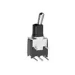
PANEL
PCB SWITCHES
-
SW
03
18
TL
TL series
Subminiature washable toggle switches
DISTINCTIVE FEATURES
Process sealed
Single piece case
Front and rear sealing
Wide variety of contact materials
Same PCB layout as TP, TR and TG subminiature switches
ENVIRONMENTAL SPECIFICATIONS
• Operating temperature : -30 °C to +85 °C (-22 °F to +185 °F)
• Moisture : 21 days 95 % (NFC 20-603 - IEC 68-2-3)
ELECTRICAL SPECIFICATIONS
• �Max. current/voltage rating with resistive load :
- gold plated contacts : 0.4 VA 20 V max. AC or DC
- silver plated contacts : 0.5 A 48 V max. AC or DC
• Minimum load : 10 mA 50 mV - 10 µA 5 VDC
• Contact resistance : 20 mΩ max.
• Insulation resistance : 1,000 MΩ min. at 500 VDC
• �Dielectric strength :
1,000 Vrms 50 Hz min. between terminals and frame
500 Vrms 50 Hz min. between terminals
• Electrical life at full load :
Contacts
Number of cycles
2 positions
3 positions
Gold plated
60,000
30,000
Silver plated
20,000
10,000
GENERAL SPECIFICATIONS
• Strength of terminals : pull-out force - 10 N max.
• Cleaning : solvents or water + detergent
• Wave soldering : 260 °C (500 °F) - 5 sec.
The company reserves the right to change specifications without notice.
1
�Subminiature washable toggle switches
MATERIALS
• Case : PBT
• Actuator : brass, nickel plated
• �Contacts and terminals :
0 : brass, gold plated
1 : brass, silver plated
3 : brass, gold plated (1,27 micron gold)
8 : contact brass, gold plated + tin plated terminals
9 : contact brass, gold plated (1,27 micron gold) + tin plated
terminals
• Terminal seal : epoxy
APEM products may be recycled at end-of-life for the re-claiming of valuable metal
components.
TERMINALS
3.30
(.129)
15.20
(.598)
0.70
(.027)
0.70
(.027)
ELECTRICAL FUNCTIONS
1 2 3
2
8.65
(.340)
4.60
(.181)
9.60
(.377)
5.00
(.196)
5.55
(.218)
3.05
(.120)
14.30
(.562)
PCB MOUNTING
14.20
(.559)
PCB SWITCHES
TL series
�Subminiature washable toggle switches
BUILD YOUR PART NUMBER
BASIC PART NUMBER
TL
ELECTRICAL FUNCTIONS
NUMBER OF POLES
SERIES
TERMINALS
3
Single pole
6
ON
-
ON
P0
Straight PC
4
Double pole
9
ON
OFF
ON
Y0
Bracket mounting
7
MOM
OFF
MOM
W0
8
ON
OFF
MOM
Right angle,
horizontal mounting
2
ON
-
MOM
WW
Right angle, vertical
mounting
OPTIONS
CONTACT AND TERMINAL MATERIALS
With blue case
With black case
00
Short lever,
nickel plated
50
Short lever,
nickel plated
Brass, gold plated
(1.27 micron gold)
01
Short lever,
black
51
Short lever,
black
Contact brass,
gold plated + tin
plated terminals
02
Long lever,
nickel plated
52
Long lever,
nickel plated
03
Long lever,
black
53
Long lever,
black
04
Medium lever,
nickel plated
54
Medium lever,
nickel plated
05
Medium lever,
black
55
Medium lever,
black
40
Short insulated
lever
56
Cylindrical lever,
nickel plated
30
Long insulated
lever
94
Short insulated
lever
90
Long insulated
lever
0
Brass, gold plated
1
Brass, silver plated
3
8
9
Contact brass,
gold plated (1.27
micron gold) + tin
plated terminals
(SP only)
SPECIAL OPTIONS
LEVER STYLES / CASE COLORS
00
No special requirement
07
Trimmed terminals - length 3.2 (.125)
08
Extended terminals
18
Switch without ground plate
20
Ground plate with 2 pins
25
Trimmed terminals - length 5 (.196)
50
Crimped ground plate pins
ABOUT THIS SERIES
On the following pages, you will find successively basic part numbers of switches and options in the same order as in above chart.
Notice : please note that not all combinations of above numbers are available. Refer to the following pages for further information.
3
PANEL
PCB SWITCHES
TL series
�Subminiature washable toggle switches
Shown with standard lever
STRAIGHT PC TERMINALS : TL..P0
III
I
Ø4.60
(.181 DIA)
Single pole Double pole
-
ON
TL39P0
TL49P0
ON
OFF
ON
TL37P0
TL47P0
MOM
OFF
MOM
TL38P0
TL48P0
ON
OFF
MOM
TL32P0
TL42P0
ON
-
MOM
1
1 2 3
2.54 4 5 6
(.100)
0.70
(.027)
III
5.08
(.200)
9.10
(.358)
II
2.54
(.100)
I
Ø1.10
(.043 DIA)
3.80
(.149)
24˚
5.30
(.208)
Ø2.50
(.098 DIA)
Ø1.10
(.043 DIA)
4
8.10
(.318)
5.00
(.196)
STRAIGHT PC TERMINALS
BRACKET MOUNTING : TL..Y0
0.50
(.019)
2.54
(.100)
4.20
(.165)
Ø5.00
(.196 DIA)
6.10
(.240)
ON
8.10
(.318)
TL46P0
3.30
(.129)
TL36P0
Ø1.10
(.043 DIA)
3.80
(.149)
5.08
(.200)
II
I
1.00
(.039)
III
II
24˚
5.30
(.208)
Ø2.50
(.098 DIA)
10.16
(.400)
Ø4.60
(.181 DIA)
TL38Y0
TL48Y0
ON
OFF
MOM
TL32Y0
TL42Y0
ON
-
MOM
ON
Single pole Double pole
TL36W0
TL46W0
ON
-
TL39W0
TL49W0
ON
OFF
ON
TL37W0
TL47W0
MOM
OFF
MOM
TL38W0
TL48W0
ON
OFF
MOM
TL32W0
TL42W0
ON
-
MOM
4.20
(.165)
ON
Single pole Double pole
TL36WW
TL46WW
ON
-
TL39WW
TL49WW
ON
OFF
ON
TL37WW
TL47WW
MOM
OFF
MOM
TL38WW* TL48WW* ON
OFF
MOM
TL32WW* TL42WW* ON
-
MOM
I
II
4.20
(.165)
5.08
(.200)
2.54
(.100)
ø1.10
(.043 DIA)
III
6
8.65
(.340)
5.08
(.200)
Ø1.10
(.043 DIA)
3.80
(.149)
Ø5.00
(.196 DIA)
0.70
(.027)
2.54
(.100)
3.30
(.129)
24˚
Ø4.60
(.181 DIA)
5.00
(.196)
4
9.60
(.377)
8.10
(.318)
0.50
(.019)
I
3
6
2.54
(.100)
0.50
(.019)
Ø2.5
(.098 DIA)
II
ø5.00
(.196 DIA)
5.55
(.218)
ø1.10
(.043 DIA)
3.80
(.149)
ø4.60
(.181 DIA)
3 2 1
6 5 4
3.30
(.129)
RIGHT ANGLE TERMINALS
VERTICAL MOUNTING : TL..WW
III
II III
24°
5.30
(.208)
I
2.54
(.100)
9.10
(.358)
0.70
(.027)
II
*Functions 2 and 8 : reversed connection available. On request.
I
ø2.50
(.0.98 DIA)
III
5.08
(.200)
10.16
(.400)
5.00
(.196)
RIGHT ANGLE TERMINALS
HORIZONTAL MOUNTING : TL..W0
0.70
(.027)
2.54
(.100)
5.08
(.200)
MOM
2.54
(.100)
OFF
10.16
(.400)
3
6
2
5
1
4
3.30
(.129)
5.08
(.200)
2.54
(.100)
MOM
0.50
(.019)
3
5.08
(.200)
TL47Y0
1 2 3
4 5 6
5.08
(.200)
TL37Y0
0.40
(.015)
2.54
(.100)
ON
5.08
(.200)
OFF
5.08
(.200)
ON
9.20
(.362)
TL49Y0
Ø1.10
(.043 DIA)
4
5.08
(.200)
TL39Y0
1
3.50
(.137)
ON
1.00
(.039)
-
5.30
(.208)
ON
9.20
(.362)
TL46Y0
2.54
(.100)
4.20
(.165)
5.08
(.200)
TL36Y0
Ø5.00
(.196 DIA)
3.50
(.137)
I
5.70
(.224)
II
8.60
(.338)
III
Single pole Double pole
3.30
(.129)
PCB SWITCHES
TL series
5.08
(.200)
9.10
(.358)
5.08
(.200)
Ø1.10
(.043 DIA)
�Subminiature washable toggle switches
CONTACT AND TERMINAL
MATERIALS
BASIC P/N
0
1
3
8
9
Brass, gold plated
Brass, silver plated
Brass, gold plated (1.27 micron gold)
Contact brass, gold plated + tin plated terminals
Contact brass, gold plated (1.27 micron gold) + tin plated terminals (single pole only)
LEVER AND CASE STYLES
BASIC P/N
SHORT - STANDARD
LONG
Ø2.50
(.098 DIA)
6.10
(.240)
4.20
(.165)
CASE
Ø4.60
(.181 DIA)
3.80
(.149)
Ø5.00
(.196 DIA)
4.20
(.165)
Blue
Black
Nickel plated
00
50
Black
01
51
LEVER
MEDIUM
CASE
9.40
(.370)
3.80
(0149)
24˚
24˚
Ø4.60
(.181 DIA)
6.10
(.240)
5.30
(.208)
Ø2.50
(.098 DIA)
Ø5.00
(.196 DIA)
Blue
Black
Nickel plated
02
52
Black
03
53
LEVER
CYLINDRICAL
7.40
6.10
(.240) (.291)
3.80
(.149)
4.20
(.165)
CASE
24˚
Ø4.60
(.181 DIA)
3.80
(.149)
Ø4.60
(.181 DIA)
Ø5.00
(.196 DIA)
4.20
(.165)
Ø5.00
(.196 DIA)
Blue
Black
Nickel plated
04
54
Black
05
55
LEVER
6.50
(.255)
Ø1.60
(.062 DIA)
24˚
6.10
(.240)
Ø2.50
(.098 DIA)
CASE
LEVER
Nickel plated
Blue
Black
-
56
INSULATED LEVERS
Protected against electrostatic discharges (ESD) up to 10 KV.
Ø2.50
(.098 DIA)
5.50
(.216)
Ø4.60
(.181 DIA)
3.80
(.149)
4.20
(.165)
Ø5.00
(.196 DIA)
4.20
(.165)
6.10
(.240)
3.80
(.149)
CASE
LEVER
Black
24˚
24˚
Blue
Black
40
94
CASE
LEVER
Black
Ø4.60
(.181 DIA)
7.60
6.10
(.240) (.299)
Ø2.50
(.098 DIA)
Ø5.00
(.196 DIA)
Blue
Black
30
90
5
PANEL
PCB SWITCHES
TL series
�Subminiature washable toggle switches
SPECIAL OPTIONS
BASIC P/N
00
No special requirement
07
Trimmed terminals - length 3,2 mm (.125) for TL..WW models only
08
Extended terminals for TL..W0 models only
18
Switch without ground plate for TL..WW models only
20
Ground plate with 2 pins for TL..WW models only
25
Trimmed terminals - length 5 mm (.196) for all models, except TL..WW
50 �Crimped ground plate pins.
Retains switch on PCB during handling and wave soldering.
For models TL..W0, TL..WW and TL..Y0 single and double pole.
10.16
(.400)
5.08
(.200)
2.70
(.106)
12.50
(.492)
2.54
(.100)
3.20
(.125)
10.16
(.400)
PCB SWITCHES
TL series
Ø1.10
(.043 DIA)
07
08
5.00
(.196)
25
6
50
18
20
�Mouser Electronics
Authorized Distributor
Click to View Pricing, Inventory, Delivery & Lifecycle Information:
Apem:
TL36P000200 TL37W000050 TL32W005000 TL32WW05000 TL36P019400 TL36W000000 TL36W005000
TL36W005200 TL36WW00000 TL36WW05000 TL37W000000 TL38W009000 TL39P000200 TL39P005000
TL39W005000 TL39WW00000 TL39WW05000 TL42P005000 TL42W005000 TL42WW05000 TL46P005000
TL46W005000 TL46W005200 TL49P000200 TL49P080400 TL49W000000 TL49W000250 TL49W005000
TL49WW05000 TL32W000000 TL32Y000000 TL37WW00000 TL37Y000000 TL38W000000 TL38Y000000
TL39Y000000 TL42W000000 TL42WW00000 TL46W000000 TL46WW00000 TL46Y000000 TL47WW00000
TL48WW00000 TL48Y000000 TL49Y000000 TL32P000000 TL32P005000 TL32W000050 TL32WW00050
TL32Y000050 TL36P000000 TL36P005000 TL36W000050 TL36W004050 TL36W019400 TL36WW00050
TL36Y000050 TL37MW05000 TL37P000000 TL37P005000 TL37WW00050 TL37Y000050 TL38P000000
TL38W000050 TL38W005050 TL38WW00050 TL39P000000 TL39W000000 TL39W000050 TL39W005050
TL39WW00050 TL39WW05050 TL39Y000050 TL39Y081650 TL42P000000 TL46MW00000 TL46P000000
TL46W000050 TL46WW00050 TL46Y000050 TL49P000000 TL49W000050 TL49Y000050 TL39W005018
TL36W005050 TL37WW05100 TL36WW05200 TL46P010000 TL46W015050 TL36W004000 TL47W000400
TL46WW05000 TL36Y000200 TL49P005000 TL46W000400 TL39W004000 TL36W000200 TL36Y004000
TL37W004050 TL46WW04000
�