承
认
书
APPROVAL SHEET
客 户 名 称:
Customer
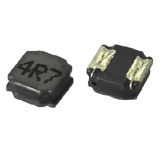
功率电感器
Power Inductor
产 品 名 称:
Part Name
客 户 料 号:
Customer P/N
物 料 描 述:
Material description
产 品 规 格:
PRS4018-S00 Series
Specification
版 本 号:
22.01
Version No.
日
期:
2022-1-28
DATE
制造
客户
Manufacturer
Customer
拟制
审核
确认
检验
审核
批准
Draft by
Checked by
Approve by
Check by
Checked by
Approval by
唐程华
冯东梅
冯东梅
�履历表
Resume
版本
Ver. No.
修 改 明 细
Modify Details
修改
Reviser
日期
Date
22.01
首次发行 Initial issue
唐程华
2022-1-28
Page 1 of 11
�目
录
TABLE OF CONTENTS
1
适用范围 Scope
2
型号表示办法 How To Order
3
尺寸与结构 External Dimensions and Structural Diagram
4
测试条件 Testing conditions.
5
工作温度范围 Operating Temperature Range
6
电气性能 Performance Specification
7
可靠性 Reliability Data
8
包装 Package
9
环保情况说明 Environmental Protection Statement
10
推荐使用的焊接曲线 Recommended soldering profile
11
清洗 Cleaning
12
贮存方法 Storage Methods
13
使用注意事项 Precautions For Use
Page 2 of 11
�1. 适用范围 Scope.
本规格书适用于 PRS4018-S00 系列贴片功率电感器。
This specification applies to the PRS4018-S00 series of SMD power inductors.
2. 型号表示办法 How To Order.
PRS
4018
①
②
6R8
□
T
S □□
③
④
⑤
⑥
-
①产品代号,Product symbol.
②尺寸代码,Dimension code, 长度与厚度, Length and thickness.
③电感量标称值,Inductance,1R0→1.0µH,100→10µH,101→100µH.
④电感量公差代码,Inductance Tolerance code, N ±30%,M ±20%.
⑤包装代码,T-编带卷盘;Packing code: T-Tape & reel.
⑥内部代码,Internal code.
3. 尺寸与结构 External Dimensions and Structural Diagram.
单位 Unit:mm
3.1. 尺寸 External Dimensions
I
J
A
F
G
Marking
F
I
E
H
B
C
RECOMMENDED
LAND PATTERNS
顶部印字 Marking:1.0µH→1R0,10µH→100,100µH→101,1000µH→102
A
B
4.0±0.2
4.0±0.2
C
E
1.80MAX 2.60±0.3
F
typical
G
typical
1.2
1.6
Page 3 of 11
H
I
J
typical typical typical
3.6
1.4
1.6
�3.2. 结构图 Structural drawing:
③
②
①
No.
部位 Component
材料 Material
①
磁芯 Core
镍锌铁氧体磁芯
Ni-Zn ferrite core
②
线圈 Winding
漆包线
Enamelled Wire
③
保护层 Shield
导磁胶
magnetic glue
④
电极 Electrode
底层—银 Substrate—Ag
镀层—镍层 Base plating—Ni
镀层—锡层 Base plating—Sn
表层—锡/铜 Surface solder—Sn/Cu
④
4. 测试条件 Testing conditions.
4.1. 除非另有规定,否则在以下条件下测试. Unless otherwise specified
温度:常温
Temperature : Ordinary Temperature
20±15 ℃
湿度:常湿
Humidity: Ordinary Humidity
65±20 % RH
4.2. 当对测量结果有疑问时 In case of doubt
温度
Temperature
20±2 ℃
湿度
Humidity
65±5 % RH
大气压
Atmospheric Pressure
86 to 106 kPa
4.3. 测试示意图 Test schematic diagram.
LCR METER
LCUR
LPOT
HPOT
HCUR
LCUR
LPOT
HPOT
HCUR
Thermometer
DC Bias Current Source
LCUR
LCR METER
LCUR
LPOT
LPOT
HPOT
HCUR
+
Inductor
HPOT
HCUR
Thermocouple
Inductor
Ls & RDC test schematic diagram
Isat & Irms test schematic diagram
5. 工作温度范围 Operating Temperature Range
-40℃~+125℃,包括自身发热。Including self-heating
Page 4 of 11
-
�6. 电气性能 Performance Specification
6.1. 电气特性 Electrical characteristics
客户料号
风华型号
电感量
直流电阻
饱和电流
温升电流
印字
Customers
Fenghua
Inductance
Direct Current
Saturation
Temperature
Marking
Part No.
Part No.
Resistance
Current
Rise Current
Ls
RDC
Isat
Irms
(µH)
(Ω)
(A)
(A)
PRS4018-R24NTS00
0.24 ±30%
0.014 ±30%
9.00
5.00
R24
PRS4018-R47NTS00
0.47 ±30%
0.021 ±30%
6.50
4.00
R47
PRS4018-R68NTS00
0.68 ±30%
0.020 ±30%
4.90
3.30
R68
PRS4018-1R0NTS00
1.00 ±30%
0.030 ±30%
4.30
2.00
1R0
PRS4018-1R5NTS00
1.50 ±30%
0.040 ±30%
3.35
1.80
1R5
PRS4018-2R2MTS00
2.20 ±20%
0.045 ±30%
2.70
1.65
2R2
PRS4018-2R7MTS00
2.70 ±20%
0.058 ±30%
2.30
1.45
2R7
PRS4018-3R3MTS00
3.30 ±20%
0.070 ±30%
2.45
1.23
3R3
PRS4018-4R7MTS00
4.70 ±20%
0.090 ±30%
1.70
1.20
4R7
PRS4018-5R6MTS00
5.60 ±20%
0.107 ±30%
1.60
1.50
5R6
PRS4018-6R8MTS00
6.80 ±20%
0.110 ±30%
1.45
1.06
6R8
PRS4018-8R2MTS00
8.20 ±20%
0.160 ±30%
1.35
0.90
8R2
PRS4018-100MTS00
10.00 ±20%
0.180 ±30%
1.30
0.84
100
PRS4018-120MTS00
12.00 ±20%
0.190 ±30%
1.10
1.00
120
PRS4018-150MTS00
15.00 ±20%
0.250 ±30%
0.94
0.65
150
PRS4018-220MTS00
22.00 ±20%
0.360 ±30%
0.80
0.59
220
PRS4018-330MTS00
33.00 ±20%
0.530 ±30%
0.65
0.49
330
PRS4018-390MTS00
39.00 ±20%
0.670 ±30%
0.60
0.45
390
PRS4018-470MTS00
47.00 ±20%
0.650 ±30%
0.57
0.42
470
PRS4018-560MTS00
56.00 ±20%
0.900 ±30%
0.51
0.38
560
PRS4018-680MTS00
68.00 ±20%
1.000 ±30%
0.47
0.32
680
PRS4018-820MTS00
82.00 ±20%
1.300 ±30%
0.43
0.28
820
PRS4018-101MTS00
100.00 ±20%
1.500 ±30%
0.40
0.25
101
Isat:指使电感量比初始值下降约 30%的电流值,加载电流的时间 1 秒以内。
The DC current at which the inductance drops approximate 30% from its value without current, Load current time within1 s.
Irms: 指使电感器表面温度上升 40℃的电流值。
The DC current is inductor surface temperature to rise by 40℃.
6.2. 测试条件与仪器 Test condition & equipment:
项目 Item
测试条件 Test condition
测试仪器 Test equipment
电感量 Ls
100KHz/500mV
HP4263B\IM3532-50 or equivalent
直流电阻 RDC
直流电
HP4263B\RM3545 or equivalent
饱和电流 Isat
100KHz/500mV
Microtest 6379 & 6220 or equivalent
温升电流 Irms
ambient temperature 20℃
Microtest 6379 & 6220 or equivalent
direct-current
Page 5 of 11
�6.3. 特性曲线图 Characteristic Curve
Page 6 of 11
�7. 可靠性 Reliability Data
序号
No.
7.1
7.2
项目
Items
绝缘电阻
Insulation Resistance
可焊性
Solderability
耐焊接热
7.3
7.4
7.5
7.6
Resistance to Soldering
Heat
端子强度
Adhesion of terminal
electrode
要求
Requirements
试验方法及备注
Test Methods and Remarks
≥100MΩ
在电感器线圈和磁芯之间施加
100 V 直流电压保持 60s。
100 V DC between inductor coil and core
for 60 seconds.
电极面 95%以上覆盖新的焊料。
95% or more of electrode area shall
be coated by new solder.
在 245 ℃±5 ℃ 熔 融 的 焊 锡
(96.5Sn/3.0Ag/0.5Cu)中浸 5 s±1 s。
Dip pads in flux and dip in solder pot
(96.5Sn/3.0Ag/0.5Cu) at
245 ℃±5 ℃ for (5±1) seconds.
外观无可见机械损伤;
电感量变化率:±10%以内。
No visible mechanical damage.
Inductance change: Within ±10%
在 260 ℃±5 ℃ 熔 融 的 焊 锡
(96.5Sn/3.0Ag/0.5Cu)中浸 10 s±1 s。
Dip pads in flux and dip in solder pot
(96.5Sn/3.0Ag/0.5Cu) at
260℃±5 ℃ for (10±1) seconds.
将电感器用 260 ℃±5 ℃,20 s±5 s 焊在带
元件的端子与本体结合无松动、无 有 0.3 mm 厚锡膏的基板上,然后用冶具
垂直电极面方向加压
脱落。
10 N,10 s ±1 s。
Strong bond between the pad and Inductors shall be subjected to
260 ℃ ±5 ℃ for 20 s±5 s Soldering in
the core, without come off PC the base whit 0.3mm solder. And then
aplomb electrode way plus tax
board.
10 N for 10 ± 1s seconds.
耐高温
High temperature
外观无可见机械损伤;
电感量变化率:±10%以内。
No visible mechanical damage.
Inductance change: Within ±10%
温度+125 ℃± 2 ℃,时间 1000+24
在室温
0 h,
下放置 2 小时后、48 小时内测试。
Temperature 125 ℃ ± 2 ℃, time 1000+24
0
h,Test within 48 hours after 2 hours of
placement at room temperature
耐低温
Low temperature
外观无可见机械损伤;
电感量变化率:±10%以内。
No visible mechanical damage.
Inductance change: Within ±10%
温度-40 ℃ ±2 ℃,时间 1000+24
0 h;在室温
下放置 2 小时后、48 小时内测试。
Temperature -40 ℃ ± 2 ℃, time 1000+24
0 h;
Test within 48 hours after 2 hours of
placement at room temperature
Page 7 of 11
�(续上表 Continue on the table)
序号
No.
项目
Items
要求
Requirements
试验方法及备注
Test Methods and Remarks
7.7
温度循环
Temperature
Cycling
外观无可见机械损伤;
电感量变化率:±10%以内。
No visible mechanical damage.
Inductance change: Within ±10%
7.8
温度特性
Temperature
characteristic
电感量变化率 Pc-b,Pc-d 不超过
±20%。
Inductance change Pc-b,Pc-d:
Within ±20%
7.9
7.10
恒定湿热
Constant damp
heat
高温负载
(寿命)
High-temperature
load
(Life-span)
外观无可见机械损伤;
电感量变化率:±10%以内。
No visible mechanical damage.
Inductance change: Within ±10%
外观无可见机械损伤;
电感量变化率:±10%以内。
No visible mechanical damage.
Inductance change: Within ±10%
(-40±3) ℃,时间(30±3) min ↔
(125℃±2) ℃/(30±3) min,转换时间(2~3) min,循环
32 次;在室温下放置 2 小时后、48 小时内测试。
The test sample shall be placed at (-40±3)℃ and
(125±2)℃ for (30±3) min, different temperature
conversion time is 2~3 minutes. The temperature
cycle shall be repeated 32 cycles. Test within 48
hours after 2 hours of placement at room
temperature.
a:+20 ℃ (30~45) min →
b: -40 ℃ (30~45) min →
c: +20 ℃ (30~45) min →
d: +125 ℃ (30~45) min →
e: +20 ℃ (30~45) min
Pc -b =
Lb − Lc
Ld − Lc
×100% ; Pc -d =
×100%
Lc
Lc
将电感器放置在于湿度(90~95)%RH,温度
60 ℃±2 ℃的环境中存放 1000+24
0 h,在室温下放置
2 小时后、48 小时内测试。
Place inductors in humidity (90~95)%RH, 60 ℃ ±
2 ℃ temperature 1000+24
Test within 48 hours
0 h,
after 2 hours of placement at room temperature.
温度 85 ℃±2℃,时间 1000+24
0 h,施加额定电流,在
室温下放置 2 小时后、48 小时内测试。
Temperature 85 ℃ ± 2 ℃, Time 1000+24
0 h,Apply a
rated current, Test within 48 hours after 2 hours of
placement at room temperature.
注:加载电流时零件表面温度超过 125℃的,需要
对电流降额到零件表面温度不超过 125℃。
Note: If the surface temperature of the part over
125 ℃ when the current is loaded, the current need
to reduce until the surface temperature of the part
less than 125 ℃.
Page 8 of 11
�8. 包装 Package
8.1. 载带尺寸 Tape Dimension(单位:毫米 Unit:mm)
P0
T
B0
W
F
D
E
P2
D1
P
A0
K0
W
A0
B0
D
D1
E
F
K0
P0
P2
P
T
12±0.5
4.3±0.3
4.3±0.3
1.5±0.3
1.5MIN
1.75±0.3
5.5±0.3
2.1±0.3
4.0±0.3
2.0±0.3
8.0±0.3
0.30±0.10
a
b
6R8
6R8
6R8
6R8
6R8
6R8
6R8
6R8
8.2. 供料方向 Direction of feed(单位:毫米 Unit:mm)
c
Direstion of feed
供料方向
D
底部视图
A
B
C
D
a
b
c
330
Typical
100
Typical
13
Typical
12.4
Typical
空带
Blank portions
装元件
Chip cavity
引带
Leader
8.3. 包装数量 Packing quantity
卷盘 Reel
纸盒 Box
(PCS)
(PCS)
纸箱 Carton
(PCS)
3,000
15,000
45,000
8.4. 剥离力要求 Peeling required
8.4.1. F 力大小 F force:10~130g;
8.4.2. 面带剥离速度 Peeling speed:300mm/min±10%;
8.4.3. 面带剥离角度 Peeling angle:165°~180°。
9. 环保情况说明 Environmental Protection Statement
RoHS 指令:本公司产品符合 RoHS 指令。
Response to RoHS directive:Our products are RoHS compliance.
Page 9 of 11
�10. 推荐使用的焊接曲线 Recommended soldering profile
10.1.本产品建议使用回流焊接法。
Applicable soldering process to the products is reflow soldering.
10.2.焊接材料 Soldering Materials
⑴焊料 Solder:Sn-3.0Ag-0.5Cu
⑵助焊剂:使用松香基助焊剂,禁止使用卤化物含量超过 0.2wt%的强酸性助焊剂和水溶性助焊剂。
Flux: Use rosin-based flux, but not strongly acidic flux (with chlorine exceeding 0.2 wt%). Do not use
water-soluble flux.
10.3.焊接曲线 Soldering Profile
10.4.烙铁焊接 Soldering Iron
使用烙铁进行返修时要求在 150℃下预热至少 1 分钟,不能直接用焊头接触磁体,返修焊接条件如下:
Reworking with electric soldering iron must preheating at 150℃ for 1 minute is required, and do not directly touch
the core with the tip of the soldering iron. The reworking soldering conditions are as follows:
10.4.1. 烙铁头温度 Temperature of soldering iron tip:350℃;
10.4.2. 烙铁输出功率 Soldering iron power output:≤30W;
10.4.3. 烙铁头直径 Diameter of soldering iron end:≤1.0mm;
10.4.4. 焊接时间 Soldering time:
很抱歉,暂时无法提供与“PRS4018-2R2MTS00”相匹配的价格&库存,您可以联系我们找货
免费人工找货- 国内价格
- 20+0.57250
- 100+0.34150
- 500+0.23910
- 3000+0.17080
- 6000+0.17080
- 30000+0.17080


 工商网监
湘ICP备2023018690号
工商网监
湘ICP备2023018690号
