NOW PART OF
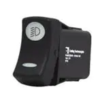
W-Series
Sealed Rocker Switches
PROD UC T WE BP A GE
request sample, configure part
The W-Series features complete IP68 protection, even
below the panel, where the critical connection is made
from your wiring harness. When used in conjunction with
the integrated connector, the totally submersible W-Series
provides a seal for up to ten individual wires, assuring
compatibility with even the most complex circuitry.
1-2
Poles
.4-10 12-24 IP68 Sealing
Amps
Typical Applications
∙ Marine
∙ On/Off-Highway
www.carlingtech.com
860.793.9281
sales@carlingtech.com
VDC
Above/Below-Panel
�Design Features
ILLUMINATION
Choice of highly reliable SMT LED
or incandescent lighting with 21
dependent or independent circuit
options.
BODY
One piece polyester 94V0
seamless body acts as an
umbrella to protect critical
internal components.
2.
TRI-SEAL DESIGN
Sealing at actuator, an insert molded
neoprene base seal, along with wire
lead seals, assures water tight, fully
submersible protection.
ROLLER PIN
Proven reliable mechanism is
lubricant free and allows for 100k
electrical and 250k mechanical
cycles, and withstands extreme
temperatures from -40˚C to +85˚C.
INTEGRATED CONNECTOR
Accommodates Tyco/Amp .110
junior power timer contacts with
twin locking tabs to provide a
safe, secure, sealed connection.
�Tech Specs
Environmental
Electrical
Contact Rating
.4VA @ 24VDC
10 amps, 3-24VDC
Sealing
IP68, for above and below-panel
components of actual switch only
Dielectric Strength
1500 Volts RMS
Insulation Resistance
50 Megohms
Corrosion/ Chemical
Splash
Flowing Mixed Gas (FMG)
Class III 3 year accelerated
exposure per ASTM B-827, B-84
Initial Contact Resistance
10 milliohms max. @ 4VDC
Operating Temperature
Life
Up to 100,000 cycles, circuit
and load dependent
-40°C to +85°C, 22 cycles, 300
hours
Vibration 1
Contacts
Silver tin-oxide, 88/12
Per Mil-Std 202F, Method 204D
Test Condition A 0.06 DA or 10G’s
10-500 Hz.
Terminals
Copper with silver or gold plating
Vibration 2
Quick
Connect terminations.
Voltage
3-24 VDC
Overcurrent
15A for 50 cycles
Resonance search
24-50 Hz 0.40 DA
50-2000 ±10 G’s peak
Results Horizontal Axis 3-5 G’s max
Random
24 Hz
0.06 PSD-Gsq/Hz
60 Hz
0.50
100 Hz
0.50
200 Hz
0.025
2000 Hz 0.025
Handling/Drop
One meter onto concrete floor
Salt Spray
Per Mil-Std 202F, Method 101D,
Test Condition A, 48 Hrs.
Dust
IP6X
Thermal Shock
Per Mil-Std 202F, Method 107F,
Test Condition A, -55°C to 85°C
Test criteria - pre and post test
contact resistance
Moisture Resistance/
Humidity
Per Mil-Std 202F,
Method 106F, Test Criteria - pre
and post test contact resistance
Physical
Lighted
LED - rated 100,000 hours 1/2 life
(LED is internally ballasted for
voltages to 24 VDC)
Seals
Neoprene
Base
Polyester blend rated to 125C with a UL
flammability rating of 94V0.
Actuator
Basic actuator structure molded
of thermoplastic polycarbonate
with a hard Nylon 66 thermoplastic
surface overlay.
Lens
Polycarbonate rated at 100°C
Function
2 & 3 Position Rocker Style
Operation
Maintained & Momentary
Base
PA 6/6 30GF (glass filled)
Actuator
PA 6/6 13GF
Bracket
PBT 10GF
Connector
PBT 10GF, polarized
Actuator Travel (Angular Displacement)
24° full throw
Mounting Specifications
Panel Thickness Range .032 to .125
For optimum panel fit, the following panel thicknesses are
suggested: .032, .062, .093, .125
.830[21.08]
1.450[36.83]
TEST CUT
HOLE IN
ACTUAL
MATERIAL
SWITCH
MOUNTING HOLE
3.
*Manufacturer reserves the right to change product specification without prior notice.
�Ordering Scheme
Sample
Part Number
Selection
W 11 D 2 B C 0 1 - A 7 Z 00 - 0 00
1
2.
3.
4.
5.
6.
1. SERIES
2. CIRCUIT
( ) - momentary For terminal arrangement, see dimensional specs
Position: 1
2
3
SP DP
2 & 3, 5 & 6 Connected Terminals 1 & 2, 4 & 5
11 21 ON NONE OFF
12 22 (ON)
NONE
OFF
13
23 ON
NONE (OFF)
14 24 ON
NONE ON
15 25 ON
NONE (ON)
16 26 ON
OFF
ON
17 27 ON
OFF (ON)
18 28 (ON)
OFF
(ON)
- 47
2 & 3 & 4, 5 & 6
2 & 3, 4 & 5
2 & 1, 4 & 5
- 49
2 & 3, 5 & 6
2 & 3, 4 & 5
2 & 1, 4 & 5
B
8.
9.
10.
11.
12.
13.
14.
10A 24V
Selection 6: above terminals 1 & 4; Selection 7: above terminals 3 & 6
No lamp
0
LED* Red
Amber
Green
White
2VDC
A
L F 4
6VDC
B
M G 5
12VDC
C
N H 6
24VDC
D
P J 8
* Consult factory for “daylight bright”, blue/green and white LED options.
Typical current draw for LED is 20ma.
8. BRACKET COLOR
1
D
10A 12V
G
10A 6V
H
10A 3V
.110 TAB (QC)
5. ILLUMINATION
Lamp #1:above terminals 1&4 end of switch.; Lamp #2 above terminals
3&6 end of switch. Positive (+) and negative (-) symbols apply to LED
lamps only
Actuator Lens Position
Lamps
Illumination Type
Lamp Wired to Terminals
O NONE
A
# 1
Independent
8+ 7B
# 1
Down
3+ 7C
# 2
Up
3+ 7D
# 1
Down
3+ 7
& # 2
Down
1+ 7E
# 1
Up
1+ 7
& # 2
Up
3+ 7F
# 1
Independent
8+ 7
& # 2
Up
3+ 6G
# 1
Independent
8+ 7
& # 2
Up
3+ 7H
# 2
Independent
8+ 7Selections for Single Pole Switches Only:
J
# 1
Down
3+ 8
& # 2
Independent
6+ 7K
# 1
Independent
8+ 7
& # 2
Independent
6+ 7Selections for Double Pole Switches Only:
L
# 1
Down
3+ 6M # 2
Up
3+ 6N
# 1
Down
3+ 6
& # 2
Down
1+ 4P
# 1
Up
1+ 4
& # 2
Up
3+ 6R
# 1
Down
3+ 7
& # 2
Up
6+ 7S
# 1
Down
6+ 7
& # 2
Independent
8+ 7U
# 1
Independent
8+ 7
& # 2
Independent
10+ 9V
# 2
Independent
10+ 9W # 1
Independent
8+ 7
& # 2
Independent
10+ 7Y
# 1 & # 2 Independent in Series 8+ 7Z
# 1 & # 2 Independent in Parallel 8+ 7-
1
Black
9. ACTUATOR
3
3
4. TERMINATION / BASE STYLE
2
7.
6,7. LAMP (SAME CODING FOR BOTH SELECTIONS)
W
3. RATING
Rocker
1
Black with Laser Etched
A
Black
10. LENS COLOR / STYLE - ABOVE LAMP #1 TERMINALS 1 & 4
11. LENS COLOR / STYLE - ABOVE LAMP #2 TERMINALS 3 & 6
Z - No Lens
Clear White Amber Green Red Blue
1
-
B
G
M T
-
7
C
H
N
U
3
-
D
J
P
V
-
9
E
K
R
W
5
A
-
-
-
-
Large Transparent
Large Translucent
Bar Transparent
Bar Translucent
Laser-Etched
Lens color for LEDs must be clear, white, or match color of LED.
12. ACTUATOR LENS OR BODY LEGENDS
2
00 - No Legend this location/No actuator
11 ON 12 OFF
13 I
14 O
OFF
ON
O
I
15 O O 16 O O 17 O I 18 I O
F N
N F
F
F
21
22
23
24
OFF
ON
O
I
25 O
26 O
27 O
28 I
F
N
F
For additional legend options & codes, visit us at carlingtech.com
13. LEGENDS ORIENTATION
0
1
2
3
4
No legend (used with codes 11-18 in selection 12)
Orientation 1
P
Orientation 2
P
P
Orientation 3
P
Orientation 4
1
2
14. ACTUATOR LENS LEGENDS
3
4
2
00 No legend (used with codes 11-18 in selection 12) Selection
14 required when switch requires two legends. If the two legends
consist of one lens & one body legend, lens legend must be
specified in selection 12; body legend specified in selection 14.
For standard legends, see “Standard Legend Codes” page.
For additional legends, please consult factory
Notes:
1
Custom colors are available. Consult factory.
2 White imprinting is standard on black actuators; Black imprinting is standard
on white, red & gray actuators; Custom colors are available, consult factory.
3 .4VA @ 24VDC rating is available, consult factory for circuit compatibility.
Configure Complete Part Number >
4.
COS-0026 Rev: J
*Manufacturer reserves the right to change product specification without prior notice.
Browse Standard Parts >
�Ordering Scheme
Sample
Part Number
Selection
W 11 D 2 0 W 0 J - P 7 B 00 - 0
1
2.
3.
4.
5.
6.
7.
8.
9.
10.
1. SERIES
8. BRACKET COLOR
2. CIRCUIT
9. ACTUATOR
w
( ) - momentary
For terminal arrangement, see dimensional specifications
Position: 1
2
3
SP DP
2 & 3, 5 & 6 Connected Terminals 1 & 2, 4 & 5
11 21 ON
NONE
OFF
14 24 ON
NONE
ON
3. RATING
B
D
G
H
10A 24V
10A 12V
10A 6V
10A 3V
4. TERMINATION / BASE STYLE
2
.110 TAB (QC)
5. ILLUMINATION
Lamp #1:above terminals 1&4 end of switch.; Lamp #2 above terminals
3&6 end of switch. Positive (+) and negative (-) symbols apply to LED
lamps only
Actuator Lens Position
Lamps
Illumination Type
Lamp Wired to Terminals
O NONE
C
# 2
Up
3+
7H
# 2
Independent
8+
7-
6. LOCK
W
Lock Option
7. LAMP #2
No lamp
0
LED*
Red
Amber
Green
White
2VDC
A L F 4
6VDC
B M G 5
12VDC
C N H 6
24VDC
D P J 8
* Consult factory for “daylight bright”, blue/green and white LED
options. Typical current draw for LED is 20ma.
5.
Locking Rocker
J
P
R
11.
12.
13.
1
Black
1
Black
Red
10. LENS
Z - No Lens
Clear White Amber Green Red
1
-
B
G
M
-
7
C
H
N
3
-
D
J
P
-
9
E
K
R
Blue
T
U
V
W
Large Transparent
Large Translucent
Bar Transparent
Bar Translucent
Lens color for LEDs must be clear, white, or match color of LED.
11. LOCK FUNCTION
Up
Down Lock Color
B J Black
C K White
D L Red
E M
Safety Orange
12. LASER ETCHED, LENS OR BODY LEGEND
1
00 No legend
For standard legends, see “Standard Legend Codes” page.
For additional legends, please consult factory
13. LEGENDS ORIENTATION
0
1
2
3
4
No legend
Orientation 1
Orientation 2
Orientation 3
Orientation 4
1
2
3
4
Notes:
1
White imprinting is standard on black actuators; Black imprinting is standard
on white, red & gray actuators; Custom colors are available, consult factory.
Configure Complete Part Number >
COS-0026 Rev: J
*Manufacturer reserves the right to change product specification without prior notice.
Browse Standard Parts >
�Dimensional Specs
inches [millimeters]
1.000
[25.40]
1.724
[43.78]
12°
1.962
[49.83]
.418
[10.62]
1.707
[43.36]
2.162
[54.91]
.031
[.79]
.465
[11.81]
KEYING FEATURE
TERMINAL ARRANGMENT
1.178
[29.93]
.714
[18.14]
WCH CONNECTOR
(190-31214-001)
Notes:
WCH connector is intended for use with Tyco/Amp .110 Junior Power Timer,
female contacts, and wire seals.
For 14-16 awg wire, specify Tyco/Amp P/N 927766-3
For 16-20 awg wire, specify Tyco/Amp P/N 927770-3
Tyco/Amp cable seal P/N 828904-1 (20-18 awg wire) or P/N 828905-1 (16-14
awg wire) is required for each individual wire lead, and Tyco/Amp cable
plug, P/N 828922-1, is required to seal each unused connector opening.
Consult Tyco/Amp for the cable seal recommended for your specific wire
gauge and thickness.
6.
1.664
[42.27]
.110
[2.79]
SWITCH SHOWN WITH
CONNECTOR INSTALLED
1.080
[27.43]
1.200
[30.48]
8
1
7
4
2
5
3
6
10
9
�Circuit Diagrams
CIRCUIT
CODE
CIRCUIT DIAGRAM
CIRCUIT
CODE
CIRCUIT DIAGRAM
3
3
6
23
11
2
2
5
1
3
12
3
4
6
24
2
2
3
1
13
5
3
4
6
25
2
1
2
1
3
5
3
4
6
26
14
2
2
1
5
1
3
3
4
6
27
15
2
1
2
1
3
5
3
4
6
28
16
2
2
1
3
1
17
5
3
4
6
47
2
1
5
2
3
1
18
3
4
6
49
2
3
6
2
5
21
2
5
3
6
22
2
7.
5
COS-0026 Rev: J
*Manufacturer reserves the right to change product specification without prior notice.
�Lamp Circuit Diagrams
LAMP CIRCUIT
CODE
LAMP CIRCUIT
CODE
CIRCUIT DIAGRAM
+8
A
-8
K
1
+8
+10
1
2
-7
-9
+10
V
2
1
2
-7
-7
-9
+3
-7
CIRCUIT DIAGRAM
+6
+8
+3
C
U
2
1
-7
-7
B
+6
+3
J
1
LAMP CIRCUIT
CODE
CIRCUIT DIAGRAM
+3
2
L
-6
W
1
+8
+10
1
2
-7
+1 +3
D
+3
1
2
+8
-6
M
2
Y
-1 +3
+8
+1 +3 -4 -6
1
2
N
2
1
+8 +3
1
+1 +3 -4 -6
-6
P
2
-7
1
-7
+3
2
+3
+8
2
COS-0026 Rev J
ISO compliant symbols. Consult factory for custom legends.
S
+6
2
1
-7
-7
8.
R
-7
H
2
1
+8 +3
G
Z
1
-7
-7
F
2
-7
-7
E
1
1
-7
+6
2
2
�Standard Legend Codes
YK
UA
UB
US
UV
UW
UX
UY
MP
MR
PX
MS
MT
VU
MW
NZ
NX
NY
YM
VW
PS
PW
PZ
WG
WM
RN
RP
YG
TX
VD
VE
VF
VG
SH
SM
SN
SP
SR
SY
WY
WZ
UH
UJ
PD
PE
PF
VC
VJ
UF
UG
MU
TN
NS
PB
SE
VZ
YE
NN
RW
PU
WA
YN
UE
NM
RJ
NR
YD
TL
VR
SL
VA
UC
VN
PK
VY
UZ
RH
NU
NV
RB
RC
RK
RL
MZ
RG
WS
WT
UD
UR
WD
TY
WATER
PUMP
9.
PA
UK
WR
UU
UT
YR
PM
VV
WB
TB
TC
TD
TE
MY
PV
TA
TZ
WC
PT
PN
PH
RA
TU
TT
YL
SK
VS
UL
UM
WK
TS
VT
WL
VP
YJ
PJ
RY
UP
NW
NP
RE
RF
PP
PR
TV
PC
YT
YU
PL
WJ
MV
RR
TK
RT
SZ
VX
WF
WH
PG
SJ
YA
YB
RM
TM
RD
RS
UN
TP
TR
NT
MX
YC
TW
TJ
YF
TH
TF
TG
YS
YH
SX
RZ
YP
WN
WP
WW
WX
SA
SB
SC
SD
ST
SU
WU
WV
SV
SW
VB
VH
VK
VL
VM
WE
SF
SG
SS
RU
RV
RX
CLA-0146 Rev: A
ISO compliant symbols. Consult factory for custom legends.
�Authorized Sales Representatives and Distributors
Click on a region of the map below to find your local representatives and distributors
or visit www.carlingtech.com/findarep.
CANADA
EUROPE
USA
MIDDLE
EAST
MEXICO
AFRICA
ASIA-PACIFIC
OCEANIA
SOUTH
AMERICA
About Carling
Founded in 1920, Carling Technologies is a leading manufacturer of electrical and
electronic switches and assemblies, circuit breakers, electronic controls, power
distribution units, and multiplexed power distribution systems. With six ISO9001 and
IATF16949 registered manufacturing facilities and technical sales offices worldwide,
Carling Technologies Sales, Service and Engineering teams do much more than
manufacture electrical components, they engineer powerful solutions! To learn more
about Carling please visit www.carlingtech.com/company-profile.
To view all of Carling’s environmental, quality, health & safety certifications please visit
www.carlingtech.com/environmental-certifications.
10.
© Carling Technologies, Inc.
Carling is a registered trademark of Carling Technologies, Inc. in the U.S. and other countries.
�