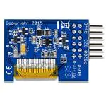
0
登录后你可以
  • 下载海量资料
  • 学习在线课程
  • 观看技术视频
  • 写文章/发帖/加入社区
会员中心
创作中心
发布
  • 发文章

  • 发资料

  • 发帖

  • 提问

  • 发视频

创作活动
410-323

410-323

  • 厂商:

    DIGILENT(迪芝伦)

  • 封装:

    -

  • 描述:

    - Displays, OLED Display Evaluation Board

  • 数据手册
  • 价格&库存
410-323 数据手册
1300 Henley Court Pullman, WA 99163 509.334.6306 www.digilentinc.com PmodOLEDrgb™ Reference Manual Revised April 26, 2016 This manual applies to the PmodOLEDrgb rev. B Overview The Digilent PmodOLEDrgb is an organic RGB LED module with a 96×64 pixel display capable of 16-bit color resolution. Features include:        96×64 pixel RGB OLED screen 0.8“ x 0.5” graphical display 16-bit color resolution Two low-power display shutdown modes Small PCB size for flexible designs (1.4“ x 1.0”) 12-pin Pmod connector with SPI interface Library and example code available in resource center The PmodOLEDrgb. 1 Functional Description The PmodOLEDrgb utilizes a Solomon Systech SSD1331 display controller to receive information from the host board and display the desired information on the OLED screen. 2 Interfacing with the Pmod The PmodOLEDrgb communicates with the host board via the SPI protocol. By driving and keeping the Chip Select (CS) line at a logic level low, users may send both commands and data streams to the display controller based on the state of the Data/Command (D/C) pin. DOC#: 410-323 Copyright Digilent, Inc. All rights reserved. Other product and company names mentioned may be trademarks of their respective owners. Page 1 of 3 PmodOLEDrgb™ Reference Manual As a graphical display interface, users may light up any individual pixel on the OLED, display predefined characters, or even load bitmaps onto the screen. Each pixel can be set to one of the 65,535 colors that are available. The OLED display has a specific power-up and power-down sequence to ensure the longevity of the device. There are two field-effect transistors (FETs) that control the display’s two power supplies. The VCCEN control toggles the positive voltage supply to the screen itself and the PMODEN control toggles the power supply ground to the display. Users may turn off either one of these controls to reduce the power consumption of the PmodOLEDrgb to approximately 200 nA. 2.1 1. 2. 3. 4. 5. 6. 7. 2.2 1. 2. 3. 4. Power-on Sequence Apply power to VCC. Send Display Off command. Initialize display to default settings. Clear screen. Apply power to VCCEN. Delay 100ms. Send Display On command. Power-off Sequence Send Display Off command Power off VCCEN Delay 100ms Power off VCC A pinout table of the PmodOLEDrgb is provided below. Pin Signal Description 1 CS Chip Select 2 MOSI Master-Out-Slave-In 3 NC Not Connected 4 SCK Serial Clock 5 GND Power Supply Ground 6 VCC Power Supply (3.3V) 7 D/C Data/Command Control 8 RES Power Reset 9 VCCEN Vcc Enable 10 PMODEN Vdd Logic Voltage Control 11 GND Power Supply Ground 12 VCC Power Supply (3.3V) Table 1. Header J1 pinout descriptions. Copyright Digilent, Inc. All rights reserved. Other product and company names mentioned may be trademarks of their respective owners. Page 2 of 3 PmodOLEDrgb™ Reference Manual Although users are welcome to create their own interface code for the PmodOLEDrgb if they so desire, preconstructed libraries that provide functions for initializing the display and rendering simple text and graphics onto the screen exist. They are available on the PmodOLEDrgb example code page and can be used as-is or as a starting point for a more sophisticated graphics library. Any external power applied to the PmodOLEDrgb must be within 2.7V and 5V; however, it is recommended that Pmod is operated at 3.3V. 3 Physical Dimensions The pins on the pin header are spaced 100 mil apart. The PCB is 1.4 inches long on the sides parallel to the pins on the pin header and 1 inch long on the sides perpendicular to the pin header. Copyright Digilent, Inc. All rights reserved. Other product and company names mentioned may be trademarks of their respective owners. Page 3 of 3
410-323 价格&库存

很抱歉,暂时无法提供与“410-323”相匹配的价格&库存,您可以联系我们找货

免费人工找货