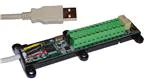
DLP-IO14
LEAD FREE
USB-Based 14-Channel
Data-Acquisition Module
FEATURES:
•
•
•
14 IO’s: 0-5V Analog, Digital In/Out, Temperature
Two Bipolar Analog Inputs; ±5V Input Range Max
All Analog Inputs: Up to 30Ksps Sample Rate and Selectable Sample Size:
Rate: 200, 500, 1K, 2K, 4K, 10K, 20K, 30K, 40K, 50K Samples Per Second
Size: 32, 64, 128, 256, 512, 1024, 2048, 4096, 8192 Samples (Binary Mode)
SPDT Latching Relay
Digital Temperature Sensor Feature Supported on 12 Digital I/O Lines
Both Binary and ASCII (HyperTerminal) Modes Available
Two 32-Bit Interrupt-Driven Event Counters; 5KHz Max Count Rate
USB Port Powered
USB 1.1- and 2.0-Compatible Interface
Small Footprint; Easily Fits on a Desktop
Easy-To-Use Programming Interface
•
•
•
•
•
•
•
•
APPLICATIONS:
•
•
•
•
•
•
•
Robotics Control
Motion Control/Presentation
Data Acquisition
Industrial/Process Control
Process Monitoring
Relay Control
Audio Analysis
1.0 INTRODUCTION
The DLP-IO14 Data-Acquisition Module is a low-cost, easy-to-use data-acquisition system for analyzing
AC voltages, controlling and monitoring processes and measuring DC voltages in the range of both 0-5
volts and ±5 volts. This module provides topside wire terminal blocks for the wiring connections.
The 14 channels on the DLP-IO14 are broken down as follows: 12 digital I/O; all of which can also be
set to Analog Input Mode (0-5V). The DLP-IO14 also provides SPDT latching relay contacts. Each of
Rev. 1.0 (June 2012)
1
© DLP Design, Inc.
�the channels and relay contacts can be controlled via simple single- and dual-byte commands. All
operational power is taken from the host PC via the USB port.
The mode of each I/O is automatically changed with each command sent. For example, if an I/O is set to
Digital Output-High and then the Digital Input Mode is selected; the I/O is first changed to Input Mode,
and then the high/low state is read and returned to the host.
2.0 SPECIFICATIONS
The DLP-IO14 is an all 5-volt system that derives its power from the host USB port. Channels have the
following capabilities:
Relay Contacts: There is one set of SPDT relay contacts on the board. These contacts are latching and
are capable of handling loads of up to 2A. The relay has two sets of SPDT contacts that have been
connected in parallel to increase their current carrying capability. (These are detailed in Section 6 under
the table describing K1.)
Analog In: Fourteen inputs can read and return the voltage on the analog inputs using a 10-bit ADC.
The maximum sample rate is 30Ksps. The input voltage range is 0-5 volts. (Refer to Section 8 of this
document for more details.) Two additional channels are dedicated to analog in only and can measure
voltages in the range of -5 volts to +5 volts.
Digital Output: Set high or clear low; configurable as digital outputs (5V). (The actual high/low voltage
depends upon sink/source current.)
Digital Input: Reads the input’s high/low state.
Temperature Measurement: Up to 12 DS18B20+ temperature sensors can be connected to Channels 1
through 12. Four settings of temperature measurement accuracy and speed are supported, as well as
the ability read the permanent serial number of the sensor.
3.0 ABSOLUTE MAXIMUM RATINGS
Stresses beyond the ranges listed below may cause permanent damage to the DLP-IO14:
Operating Temperature: 0-70°C
Voltage on Digital Inputs with Respect to Ground: -0.3V to +5.3V
Voltage on Analog Inputs with Respect to Ground: -0.3V to +5.3V
Voltage on Relay Contacts with Respect to Ground/Return: 110VDC, 125VAC
Sink/Source Current on Any I/O: 25mA
Sink/Source Current on All I/O Combined: 90mA
Rev. 1.0 (June 2012)
2
© DLP Design, Inc.
�4.0 WARNINGS
•
Unplug from the host PC before connecting to the I/O terminals on the DLP-IO14.
•
Isolate the bottom of the board from all conductive surfaces.
•
Observe static precautions to prevent damage to the DLP-IO14 module.
5.0 USB DRIVERS
USB drivers for the following operating systems are available for download from the DLP Design website:
Windows 7 x64
Windows XP
Windows XP x64
Windows Server 2003
Windows CE, 98, ME
Windows Server 2008 x64
Windows Vista
Mac OSX
Mac OS8, OS9
Linux
These drivers are available for download from the following pages: http://www.dlpdesign.com and
http://www.ftdichip.com/FTDrivers.htm.
Note: If you are utilizing the dual-mode drivers from FTDI (CDM2.x.x) and you want to use the Virtual
COM Port (VCP) drivers, then it may be necessary to disable the D2XX drivers first via Device Manager.
To do so, right click on the entry under USB Controllers that appears when the DLP-IO14 is connected,
select Properties, select the Advanced tab, put a check mark in the option for “Load VCP” and click OK.
Then unplug and replug the DLP-IO14, and a COM port should appear in Device Manager under Ports
(COM & LPT).
6.0 TERMINAL BLOCK PIN DEFINITIONS
TABLE 1
Terminal Block Pin Definitions
PIN NAME
A1
A2
G
1
2
C2
G
3
DESCRIPTION
Analog Input A1. Channel 13. Input voltage range is -5V to +5V.
Analog Input A2. Channel 14. Input voltage range is -5V to +5V.
Ground
Channel 1, Analog Input: Voltage range is 0 to +5V (see Note 1). Digital I/O:
Configurable as a digital input, a digital output (5V) or an open-drain output (5V max
pullup) (see Note 2).
Channel 2, Analog Input: Voltage range is 0 to +5V (see Note 1). Digital I/O:
Configurable as a digital input, a digital output (5V) or an open-drain output (5V max
pullup) (see Note 2).
32-bit Counter Input with a max countable frequency of 5KHz. Count increments
after toggling low then high.
Ground
Channel 3, Analog Input: Voltage range is 0 to +5V (see Note 1). Digital I/O:
Configurable as a digital input, a digital output (5V) or an open-drain output (5V max
pullup) (see Note 2). External Reference Input (see Command 0x2A for details).
Rev. 1.0 (June 2012)
3
© DLP Design, Inc.
�4
C1
5
6
COM
R
S
7
8
G
9
10
11
5V
12
G
Channel 4, Analog Input: Voltage range is 0 to +5V (see Note 1). Digital I/O:
Configurable as a digital input, a digital output (5V) or an open-drain output (5V max
pullup) (see Note 2).
32-bit Counter Input with a max countable frequency of 5KHz. Count increments
after toggling low then high.
Channel 5, Analog Input: Voltage range is 0 to +5V (see Note 1). Digital I/O:
Configurable as a digital input, a digital output (5V) or an open-drain output (5V max
pullup) (see Note 2).
Channel 6, Analog Input: Voltage range is 0 to +5V (see Note 1). Digital I/O:
Configurable as a digital input, a digital output (5V) or an open-drain output (5V max
pullup) (see Note 2).
Latching Relay Common Contact (see Note 3).
Latching Relay Reset Contact (see Note 3).
Latching Relay Set Contact (see Note 3).
Channel 7, Analog Input: Voltage range is 0 to +5V (see Note 1). Digital I/O:
Configurable as a digital input, a digital output (5V) or an open-drain output (5V max
pullup) (see Note 2).
Channel 8, Analog Input: Voltage range is 0 to +5V (see Note 1). Digital I/O:
Configurable as a digital input, a digital output (5V) or an open-drain output (5V max
pullup) (see Note 2).
Ground
Channel 9, Analog Input: Voltage range is 0 to +5V (see Note 1). Digital I/O:
Configurable as a digital input, a digital output (5V) or an open-drain output (5V max
pullup) (see Note 2).
Channel 10, Analog Input: Voltage range is 0 to +5V (see Note 1). Digital I/O:
Configurable as a digital input, a digital output (5V) or an open-drain output (5V max
pullup) (see Note 2).
Channel 11, Analog Input: Voltage range is 0 to +5V (see Note 1). Digital I/O:
Configurable as a digital input, a digital output (5V) or an open-drain output (5V max
pullup) (see Note 2).
VCC Output +5.0V. Limit current drawn from this pin to 100mA to avoid exceeding
the available current from the host USB port.
Channel 12, Analog Input: Voltage range is 0 to +5V (see Note 1). Digital I/O:
Configurable as a digital input, a digital output (5V) or an open-drain output (5V max
pullup) (see Note 2).
Ground
Notes:
1. The Analog Input Range is 0-5V. The maximum sample rate is 30Ksps. Refer to Section 8 for
more details.
2. Digital outputs can sink or source 25mA; 90mA for all outputs combined. Open-drain outputs are
implemented by making the I/O pin an input. The maximum pullup voltage is 5.0 volts.
3. Relay contacts can support resistive loads of up to 2A @ 30 VDC, 0.6A @ 110 VDC and 1 A @
125 VAC. If this value is exceeded, the DLP-IO14 can be damaged. The relay is set and
reset only under software control. For a functional schematic of the relay connections, refer to
Section 7.
Rev. 1.0 (June 2012)
4
© DLP Design, Inc.
�7.0 RELAY FUNCTIONAL SCHEMATIC
The DLP-IO14 contains one latching relay. The relay is controlled by host software. The relay contacts
R, S and COM are described in Table 1. A functional view of how the relay works is shown here:
Figure 1: Relay Functional Schematic
Note: On power-up of the DLP-IO14, the relay states will be unknown. Each can power up in either the
Set or Reset state. If a known initial state is required, the user will need to issue either a Set or Reset
Command upon power-up.
8.0 USING THE DLP-IO14
Simply connect the DLP-IO14 to the PC to initiate the loading of USB drivers. Once the USB drivers are
loaded, the DLP-IO14 is ready for use. All commands are issued as single-byte or double-byte
command packets. First a channel is set by sending an ASCII 1-9, a, b, c, d or e for the desired channel.
Then a byte is sent for the desired function. Table 2 describes all of the available functions.
You can either utilize the TestApp program provided with the DLP-IO14, or you can write your own
program in your language of choice. If the DLP-IO14 is set to ASCII mode, HyperTerminal can be used
as the user interface. Begin by opening the COM port, and then send commands as shown in Table 2
below. There is no need to set the baud rate because the DLP-IO14 uses a parallel interface between
the USB IC and the microcontroller. (The Ping Command can be used to locate the correct COM port
used for communicating with the DLP-IO14, or you can look in Device Manager to see which port was
assigned by Windows.)
TABLE 2
Command Packets
Command
Packet
Description
ASCII
Byte
Hex
Value
Ping
Issue Ping
‘
0x27
LED
Control
LED Flash,
On, Off
Channel
Select
Select the
Channel
+
.
`
1-9,
a,b,c,
d,e
0x2B
0x2E
0x60
0x310x39,
0x610x65
Relay
Control
Set/Reset
Relay
k
m
0x6B
0x6D
Rev. 1.0 (June 2012)
Return/Comments
If the DLP-IO14 is found on the selected port, N is
returned in ASCII Mode; 0x4E if in Binary Mode.
Flash LED; Nothing Returned
LED ON; Nothing Returned
LED OFF; Nothing Returned
Sets the active channel to be used with the commands
in this table. If in ASCII Mode, the channel is returned
plus CR/LF. Nothing is returned in Binary Mode.
a, b, and c are Channels 10,11 and 12 on the module;
d and e are A1 and A2 on the module.
Relay Set; Nothing Returned
Relay Reset; Nothing Returned
5
© DLP Design, Inc.
�Digital I/O
Command
Set °C / °F
Mode &
Save
Temperature Sensor
Detect
Temperature Sensor
Read
Temperature Sensor
Resolution
Set Return
Mode &
Save
Reset
32-Bit
Event
Counter
Read 32-bit
Event
Counter
INT / EXT
Voltage
Reference
Select &
Save
Select
Direction
and Output
Value
w
0x77
s
0x73
r
0x72
f
0x66
g
0x67
]
0x5D
t
0x74
-
0x2D
If a DS18B20+ sensor is detected on the current channel,
will start a temperature conversion, wait for the
conversion to complete and return data. If in ASCII
Mode, will return temperature in current °C/°F Mode plus
CR/LF. In Binary Mode, will return 2 bytes of raw sensor
data. (See Note 1.)
Set sensor resolution to 9-bit / Fast. Nothing returned.
,
0x2C
Set sensor resolution to 10-bit. Nothing returned.
0
0x30
Set sensor resolution to 11-bit. Nothing returned.
\
0x5C
Set sensor resolution to 12-bit / Slow (Default). Nothing
returned.
q
0x71
ASCII Mode selected. (Default) "ASCII mode" returned.
h
0x68
Binary Mode selected. Nothing returned.
u
y
0x75
0x79
Clear C1 Event Counter to zero. Nothing Returned.
Clear C2 Event Counter to zero. Nothing Returned.
Read the C1
and C2
Event
Counters
n
p
0x6E
0x70
Select
Internal or
External
Reference
i
0x69
x
0x78
Read and return C1 counter state.
Read and return C2 counter state.
If in Binary Mode, will return 4 bytes--MSByte first. If in
ASCII Mode, returns “C1:” or “C2:” followed by count
(base 10) and CR/LF.
Select internal 5V reference provided by the host PC
USB port. (See Note 2.) (Default) Nothing returned.
Select (user-provided) external reference connected to
Channel 3. Remember to select the reference voltage
using Command 0x2A (Set Reference Voltage). Nothing
returned. Selection is saved for power-up default.
Remember to set the reference jumper accordingly for
use with Channels A1 and A2. (See Section 9.)
Select
Temperature
Display
Mode
Detect
Sensor &
Return
Serial
Number
from Current
Channel
Convert,
Read and
Return Data
from Current
Channel
Select
Temperature
Sensor
Resolution
for the
Current
Channel
ASCII /
Binary Mode
Select
Clear C1 or
C2 Event
Counter
Rev. 1.0 (June 2012)
Output-High: Make current channel digital output and set
it high; nothing returned.
Output-Low: Make current channel digital output and
clear it low; nothing returned.
Input: Make current channel digital input and return
state. If ASCII Mode is enabled; returns ASCII 0 or 1
plus CR, LF. If Binary Mode is enabled; returns a binary
0 or 1.
Select Fahrenheit Mode and save. Nothing returned.
(Default) Selection saved for power-up default.
Select Celsius Mode and save. Nothing returned.
Selection saved for power-up default.
If a DS18B20+ sensor is detected on the current channel,
will return the 8-byte sensor serial number in bytereversed order. If in ASCII Mode, will return hex
characters. In Binary Mode, will return binary data. A
working sensor must be connected to the selected
channel.
6
© DLP Design, Inc.
�Set Sample
Rate &
Save
Two-Byte
Command
Set
Number of
Samples &
Save
Two-Byte
Command
Select the
A/D Sample
Rate Used
by
Command
0x7A
0
1
2
0x30
0x31
0x32
200s/s selected and saved.
500s/s selected and saved.
1Ks/s selected and saved.
3
0x33
2Ks/s selected and saved.
4
0x34
4Ks/s selected and saved.
Command:
‘=’ (0x3D)
Followed by
‘0’-‘7’ or
0x30-0x37
5
0x35
10Ks/s selected and saved.
6
0x36
20Ks/s selected and saved.
7
0x37
30Ks/s selected and saved.
0
1
2
0x30
0x31
0x32
Sets the A/D sample rate for Command 0x7A. The
selection is saved for power-up default. EX: 0x3D, 0x05
sets the conversion rate at 10K samples per second.
32 return samples selected and saved.
64 return samples selected and saved.
128 return samples selected and saved.
3
0x33
256 return samples selected and saved.
4
0x34
512 return samples selected and saved.
5
0x35
1024 return samples selected and saved.
6
0x36
2048 return samples selected and saved.
7
0x37
4096 return samples selected and saved.
8
0x38
8192 return samples selected and saved.
Set the
Number of
Samples
Acquired by
Command
0x7A
Command:
‘[‘ (0x5B)
Followed by
‘0’-‘8’ or
0x30-0x38
Read
Current
Setup
Set
Reference
Voltage &
Save
Two-Byte
Command
Read and
Return the
Current
Saved Setup
j
Select
Reference
Voltage for
ASCII Mode
Voltage
Calculation
0
1
2
3
4
5
6
7
8
9
Command:
‘*’ (0x2A)
Followed by
‘0’ – ‘9’.
Rev. 1.0 (June 2012)
0x6A
Sets the number of A/D samples returned from
Command 0x7A. The selection is saved for power-up
default. EX: 0x5B, 0x06 sets the number of samples to
2048.
Returns the six saved parameters. (See Table 3 for a
description of each parameter.)
In ASCII Mode, six ASCII characters (0-9) separated by
spaces are returned followed by a CR/LF.
0
1
2
3
4
5
6
7
8
9
In Binary Mode, 6 bytes are returned.
2.2V reference selected and saved.
2.5V reference selected and saved.
3.0V reference selected and saved.
3.3V reference selected and saved.
3.5V reference selected and saved.
4.0V reference selected and saved.
4.096V reference selected and saved.
4.5V reference selected and saved.
4.8V reference selected and saved.
5.0V reference selected and saved. (Default)
Reference voltage used in ASCII Mode by the DLP-IO14
for calculating voltage. (Not required in Binary Mode
since actual voltage is calculated in the host program.)
Selection is saved for power-up default. EX: *9 sent via
HyperTerminal sets 5.0 volt reference.
7
© DLP Design, Inc.
�Single A/D
Conversion
Read Analog
Voltage from
the Current
Channel and
Return to Host
v
0x76
Read a single voltage from the selected channel.
2 bytes are returned for each conversion.
If in ASCII Mode, voltage is calculated using current
voltage reference parameters (see Table 3) and
returned as an ASCII string followed by CR/LF.
If in Binary Mode, two bytes for the 10-bit A/D counts
are returned--LSByte first. To calculate voltage for
Channels 1-12:
int temp = byte2 * 255 + byte1;
float volts = temp / 1023 * reference voltage;
To calculate voltage for ch13 or ch14, *add* this line of
code:
Multiple
A/D
Conversion
Read Multiple
Analog
Voltages from
the Current
Channel and
Return to Host
z
0x7A
volts = ( volts - (vrefvoltage/2.0) ) * 2.0;
Read multiple voltages from the selected channel per
the selected setup parameters (see Table 3).
2 Bytes are returned for each conversion.
This command is only available in Binary Mode.
Two bytes for the 10-bit A/D counts from each
measurement are returned; MSByte first.
To calculate voltage for Channels 1-12:
int temp = byte1 * 255 + byte2;
float volts = temp / 1023 * reference voltage;
To calculate voltage for ch13 and ch14, *add* this line
of code:
volts = ( volts - (vrefvoltage/2.0) ) * 2.0;
Notes:
1. Requires a DS18B20+ digital temperature sensor (purchased separately). See Section 10.0 of
this document for connection details. Before issuing a Convert Sensor Command, make sure
that a digital temperature sensor is present on the selected digital I/O channel with a 1.5K-ohm
pullup resistor. (Refer to the DLP-IO14 demo code provided for temperature calculation method
in Binary Mode.) Other examples are available from www.maxim-ic.com in Application Note
AN162.pdf.
2. Using the host 5V power supply as a reference may not produce accurate voltage measurements. For better accuracy, connect and select a precision voltage reference to Channel 3. (See
Commands 0x78 and 0x2A for more details.)
Rev. 1.0 (June 2012)
8
© DLP Design, Inc.
�TABLE 3
Selectable Power-Up Default Settings
Range
0
1
2
3
4
5
6
7
8
9
Voltage
Reference
2.2V
2.5V
3.0V
3.3V
3.5V
4.0V
4.096V
4.5V
4.8V
5.0V
Sample
Rate
200s/s
500s/s
1Ks/s
2Ks/s
4Ks/s
10Ks/s
20Ks/s
30Ks/s
Number of Samples
Returned
32
64
128
256
512
1024
2048
4096
8192
°C/°F
°F
°C
Return
Mode
ASCII
Binary
Reference
Source
Internal 5V
External
Default
9.0 REFERENCE JUMPER SELECTION
A three-pin jumper selection is provided for setting the reference used by the analog input buffer for
Channels 13 and 14. These channels accept voltages in the range of ±5V if the internal reference is
selected. If the external reference is selected and an external reference voltage is applied to Channel 3,
then the input voltage range can be from ±2.2V up to ±5.0V.
Pin 1 of this 3-pin jumper is closest to Wiring Terminal A1. Place a jumper across Pins 1 and 2 to select
the external reference applied to the terminal for Channel 3. Place the jumper across 2 and 3 to select
the internal 5V reference (factory default).
Rev. 1.0 (June 2012)
9
© DLP Design, Inc.
�10.0 CONNECTING THE DIGITAL TEMPERATURE SENSOR
Up to 12 DS18B20+ digital temperature sensors can be connected to the DLP-IO14. For best
performance, use Category 5/6-type computer cable to connect the sensors to the DLP-IO14. Two
twisted pairs in the Cat 5/Cat 6 cable are required for the connection. The first twisted pair is for Power
(5V) and Ground, and the second twisted pair is for as Data and Ground. In addition, a 1.5K-ohm
pullup resistor is required for the data line.
Figure 3 shows an example of this connection using Channel 12:
DLP-IO14
Pin 1
G
12
5V
1. GND
2. DATA
3. VCC
DS18B20+
500-1.5K Ohm
Figure 3: Digital Temperature Sensor Connection Example
To detect a sensor, select a channel with a sensor connected, and then send the DLP-IO14 the Detect
Sensor Command ‘]’ (0x5D). The permanent serial number will be returned to the host PC. If the
channel is stuck Low, a “1” will be returned in the first byte on the 8 bytes returned. If no sensor is
present, then a “2” will be returned in the first byte. In these two cases, the remaining seven bytes will be
all zeroes. If a sensor is present and functional, its 8-byte serial number will be returned.
Next, send a Convert Sensor Command ‘t’ (0x74) to initiate the temperature conversion. The
temperature value is automatically returned after the conversion is complete. The conversion can take
up to 750mS to complete depending upon the resolution setting. In the lowest resolution mode, the
conversion takes approximately 100mS to complete.
Rev. 1.0 (June 2012)
10
© DLP Design, Inc.
�11.0 DEMO APPLICATION PROGRAM
A test application program called IO14GUI is provided with the purchase of the DLP-IO14 that runs on
Windows and can be used to interface with and control the DLP-IO14. (Note that the Visual C++ source
is also available with the purchase of the DLP-IO14.) This application is designed to demonstrate all of
the unit’s available features:
Figure 4: Test Application GUI
Rev. 1.0 (June 2012)
11
© DLP Design, Inc.
�12.0 MECHANICAL DIMENSIONS IN INCHES (MM) (Preliminary)
77.0 typ
(1.96m typ)
.95 typ
(24.1 typ)
.54 typ
(13.7 typ)
3
2
1
A1
5.2 typ
(132 typ)
13.0 DISCLAIMER
© DLP Design, Inc., 2000-2012
Neither the whole nor any part of the information contained herein nor the product described in this
manual may be adapted or reproduced in any material or electronic form without the prior written consent
of the copyright holder.
This product and its documentation are supplied on an as-is basis, and no warranty as to their suitability
for any particular purpose is either made or implied. DLP Design, Inc. will not accept any claim for
damages whatsoever arising as a result of the use or failure of this product. Your statutory rights are not
affected. This product or any variant of it is not intended for use in any medical appliance, device or
system in which the failure of the product might reasonably be expected to result in personal injury.
This document provides preliminary information that may be subject to change without notice.
Rev. 1.0 (June 2012)
12
© DLP Design, Inc.
�14.0 CONTACT INFORMATION
DLP Design, Inc.
1605 Roma Lane
Allen, TX 75013
Phone:
Fax:
Email Sales:
Email Support:
Website URL:
469-964-8027
415-901-4859
sales@dlpdesign.com
support@dlpdesign.com
http://www.dlpdesign.com
Rev. 1.0 (June 2012)
13
© DLP Design, Inc.
�