1300 Henley Court
Pullman, WA 99163
509.334.6306
www.digilentinc.com
PmodDHB1™ Reference Manual
Revised May 24, 2016
This manual applies to the PmodDHB1 rev. B
Overview
The Digilent PmodDHB1 is a dual H-Bridge motor driver that is capable of driving two DC motors, a bipolar stepper
motor, and other devices with inductive loads.
Features include:
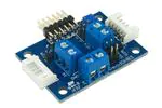
The PmodDHB1.
1
Dual H-Bridge capable of 1.5A RMS
Two quadrature encoder channels for motor feedback
Two JST 6-pin ports for connection to Digilent
motor/gearbox
Over-current protection
Recommended 10.8 V max motor voltage
Logic input voltage range of 2.5 V to 5 V
Small PCB size for flexible designs 1.3“ × 1.8” (3.3 cm × 4.6
cm)
Follows Digilent Pmod Interface Specification Type 5
Functional Description
The PmodDHB1 utilizes TI's DRV8833 to drive a variety of systems. With the two built in H-Bridges and pull down
resistors on the inputs, users may run two DC motors or a single bipolar stepper motor in fast decay mode.
The DRV8833 chip provides over-current protection on the motor drive circuits. Each internal drive FET is
independently monitored for an over-current condition and will be shut down internally to protect the chip. When
an over-current condition is sensed the chip will shut down the FET with the fault and then set the NFAULT pin low
signaling a fault condition on the chip. The remaining FETs will continue to operate as normal. When the fault
condition is over, the chip will self-reset and return the NFAULT logic level to logic high.
2
Interfacing with the Pmod
The PmodDHB1 communicates with the host board via the GPIO protocol. By driving the enable (EN) pins with a
PWM signal and a logic level low or high voltage signal on the direction (DIR) pins, users are able to run DC motors
at various speeds.
DOC#: 502-259
Copyright Digilent, Inc. All rights reserved.
Other product and company names mentioned may be trademarks of their respective owners.
Page 1 of 3
�PmodDHB1™ Reference Manual
A truth table listing out the various possible combinations and results of the EN and DIR pins is provided below:
DIR1
0
0
1
1
EN1
0
1/PWM
0
1/PWM
Result
Stop
Forward
Stop
Reverse
DIR2
0
0
1
1
EN2
0
1/PWM
0
1/PWM
Result
Stop
Forward
Stop
Reverse
Table 1. Truth table list.
Note that like all H-Bridges, it is recommended that the EN pin is driven to a low voltage state before changing the
voltage state on the DIR pin to ensure that the FETs are not short-circuited.
Two sensor feedback pins for both motors are provided so users can capture the signals coming from any Hall
Effect Sensors in quadrature.
2.1
Pinout Description Tables
Pin
1
2
3
4
5
6
Signal
EN1
DIR1
S1A
S1B
GND
VCC
Header J1
Description
Pin
Motor 1 Enable
7
Motor 1 Direction
8
Motor 1 Sensor A Feedback
9
Motor 1 Sensor B Feedback
10
Power Supply Ground
11
Power Supply (3.3V/5V)
12
Header J4 - Motor Voltage
Pin Signal
Description
1
VM
Motor Power
2
GND
Power Supply Ground
Header J5 - M1 Power
Pin Signal
Description
1
M1+
Motor 1 Positive Supply
2
M1Motor 1 Negative Supply
Header J6- M2 Power
Pin Signal
Description
1
M2+
Motor 2 Positive Supply
2
M2Motor 2 Negative Supply
Header J7- M1 Feedback
Pin Signal
Description
1
SA1-IN Sensor A From Motor 1
2
SB1-IN Sensor B From Motor 1
3
GND
Power Supply Ground
4
VCC
Power Supply (3.3V)
Signal
EN2
DIR2
S2A
S2B
GND
VCC
Description
Motor 2 Enable
Motor 2 Direction
Motor 2 Sensor A Feedback
Motor 2 Sensor B Feedback
Power Supply Ground
Power Supply (3.3V/5V)
Header J2- M1 JST 6-Pin Motor Connector
Header J3- M2 JST 6-Pin Motor Connector
Header J8- M2 Feedback
Pin Signal
Description
1
SA2-IN
Sensor A From Motor 2
2
SB2-IN
Sensor B From Motor 2
3
GND
Power Supply Ground
4
VCC
Power Supply (3.3V)
Header J9- Fault
Pin Signal
Description
1
NFAULT Overcurrent Condition
2
GND
Power Supply Ground
Header J10- Sleep
Pin Signal
Description
1
NSLEEP
Puts device into sleep state
2
GND
Power Supply Ground
Copyright Digilent, Inc. All rights reserved.
Other product and company names mentioned may be trademarks of their respective owners.
Page 2 of 3
�PmodDHB1™ Reference Manual
Any external power applied to the PmodDHB1 must be within 2.7V and 10.8V; however, it is recommended that
Pmod is operated at 3.3V.
3
Physical Dimensions
The pins on the pin header are spaced 100 mil apart. The PCB is 1.3 inches long on the sides parallel to the pins on
the pin header and 1.8 inches long on the sides perpendicular to the pin header.
Copyright Digilent, Inc. All rights reserved.
Other product and company names mentioned may be trademarks of their respective owners.
Page 3 of 3
�
很抱歉,暂时无法提供与“410-259”相匹配的价格&库存,您可以联系我们找货
免费人工找货