1300 Henley Court
Pullman, WA 99163
509.334.6306
www.digilentinc.com
PmodDPOT™ Reference Manual
Revised April 8, 2016
This manual applies to the PmodDPOT rev. A
Overview
The Digilent PmodDPOT is a digital potentiometer allowing users to set a desired resistance anywhere from 60 to a
nominal 10 kΩ.
Features include:
Digital potentiometer with 8-bit resolution
Select desired resistance from 60 Ω to 10 kΩ
Small PCB size for flexible designs 0.9“ × 0.8” (2.3 cm × 2.0
cm)
6-pin Pmod port with SPI interface
Follows Digilent Interface Specification Type 2
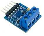
The PmodDPOT.
1
Functional Description
The PmodDPOT utilizes Analog Devices AD5160 to digitally set a desired resistance between two terminals. With
256 possible step values, a resistance between 60 Ω and 9961 Ω can be programmed. The wiper terminal has an
internal resistance of 60 Ω.
2
Interfacing with the Pmod
The PmodDPOT communicates with the host board via the SPI protocol. By bringing the Chip Select (CS) line low,
users may then provide 8-bits of data on the falling Serial Clock (SCLK) edge in SPI Mode 0. Once the 8 bits of data
have been transferred, the rising edge of the CS line loads the data into the internal register DAC, whereupon the
resistance between terminals is set.
The PmodDPOT can be utilized in two different styles: a rheostat where users set a desired resistance between one
outside terminal and the wiper terminal or in a voltage divider mode where the two outside terminals are powered
at set voltages and a ratio of resistance is specified.
DOC#: 502-239
Copyright Digilent, Inc. All rights reserved.
Other product and company names mentioned may be trademarks of their respective owners.
Page 1 of 2
�PmodDPOT™ Reference Manual
Equations for the programmable resistance values and output voltages are provided from the AD5160
datasheet below:
RWB ( D)
D
RAB RW
256
Here, RAB represents the nominal resistance of 10 kΩ and R W is the wiper terminal resistance of 60 Ω.
RWA ( D)
256 D
RAB RW
256
Here, RAB represents the nominal resistance of 10 kΩ and RW is the wiper terminal resistance of 60 Ω.
VW ( D)
RWB ( D)
R ( D)
VA WA
VB
256
256
Here, RWA and RWB are the resistances calculated in the two above equations and VA and VB are the voltages
applied at terminals A and B, respectively.
Care must be taken to ensure that current flow between the wiper terminal and either terminal A or B must be
limited to a pulsed ±20mA or a continuous 4.7mA so that the power dissipation capabilities of the on-board chip is
not exceeded.
2.1
Pinout Description Table
Pin
1
2
3
4
5
6
Signal
~CS
MOSI
(NC)
SCLK
GND
VCC
Description
Chip Select
Master-In-Slave-Out
Not Connected
Serial Clock
Power Supply Ground
Power Supply (3.3V/5V)
Any external power applied to the PmodDPOT must be within 2.7V and 5.5V; however, it is recommended that
Pmod is operated at 3.3V. Users must also ensure that any voltage applied to the outside terminals is between
GND and VCC.
3
Physical Dimensions
The pins on the pin header are spaced 100 mil apart. The PCB is 0.9 inches long on the sides parallel to the pins on
the pin header and 0.8 inches long on the sides perpendicular to the pin header.
Copyright Digilent, Inc. All rights reserved.
Other product and company names mentioned may be trademarks of their respective owners.
Page 2 of 2
�
很抱歉,暂时无法提供与“410-239”相匹配的价格&库存,您可以联系我们找货
免费人工找货- 国内价格 香港价格
- 1+114.767071+14.85540