KiCad 华秋发行版 new
供应链、设计、制造,一体成就未来
华秋PCB
高可靠多层板制造商
华秋SMT
高可靠一站式PCBA智造商
华秋商城
自营现货电子元器件商城
PCB Layout
高多层、高密度产品设计
钢网制造
专注高品质钢网制造
BOM配单
专业的一站式采购解决方案
华秋DFM
一键分析设计隐患
华秋认证
认证检测无可置疑
0
发文章
发资料
发帖
提问
发视频
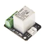
DFROBOT
-
16ARELAYMODULE(ARDUINOCOMPAT
数据手册:
很抱歉,暂时无法提供与“DFR0251”相匹配的价格&库存,您可以联系我们找货
库存:28
库存:45
库存:4


 工商网监
湘ICP备2023018690号
工商网监
湘ICP备2023018690号
