1300 Henley Court
Pullman, WA 99163
509.334.6306
www.digilentinc.com
PmodRTCC™ Reference Manual
Revised May 24, 2016
This manual applies to the PmodRTCC rev. A
Overview
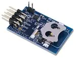
The PmodRTCC is a real-time clock/calendar powered by the Microchip® MCP79410. Through the I2C interface,
users may configure up to two alarms that can be triggered at a wide variety of possible times.
Features include:
The PmodRTCC.
1
Real-time clock/calendar with lithium coin
cell back-up
Multi-function pin output that can
generate a square wave
Two available alarms
128 bytes EEPROM
64 bytes SRAM
Small PCB size for flexible designs 1.3“ ×
0.8” (3.3 cm × 2.0 cm)
2×4-pin connector with I2C interface
Follows Digilent Pmod Interface
Specification
Library and example code available
in resource center
Functional Description
The PmodRTCC can communicate using I2C via the 8-pin header J2. Digilent boards implement several different I2C
interfaces.
2
Interfacing with the Pmod
All communications with the device must specify whether to write to the EEPROM or the RTCC registers/SRAM, as
well as a register address and a flag indicating whether the communication is a read or a write. This is followed by
the actual data transfer.
The PmodRTCC responds to two I2C addresses. Address ‘1010111’ is used for access to the EEPROM, and address
‘1101111’ is used for access to RTCC registers/SRAM.
DOC#: 502-218
Copyright Digilent, Inc. All rights reserved.
Other product and company names mentioned may be trademarks of their respective owners.
Page 1 of 2
�PmodRTCC™ Reference Manual
The device is configured by writing to the registers within the device. The time registers can be set to specific
values and a control register sets their functionality.
Pin
1&5
2&6
3&7
4&8
Signal
SCL
SDA
GND
VCC
Description
Serial Clock
Serial Data
Power Supply Ground
Power Supply (3.3V/5V)
Table 1. Pinout description table.
A full list of registers and their functionality, as well as communication specifications, can be found in the
MCP79410 datasheet available at the Microchip website.
The I2C interface standard uses two signal lines. These are I2C data (SDA) and serial clock (SCLK). These signals map
to the serial data (SDA) and serial clock (SCLK) on the MCP79410.
2.1
Power Back-up
The PmodRTCC has a holder for a 12mm lithium coin cell to power the RTCC and SRAM if VDD should ever fall
below the operating point. In order to enable this power back-up, the VBATEN bit must be set in the RTCC
registers. Compatible coin cells include BR1216, CR1216, BR1220, CL1220, CR1220, and BR1225.
Pin
1
Connector J1 – MFP Header
Signal
Description
MFP
Multi-Function Pin
2
GND
Power Supply Ground
Table 2. MFP header.
2.2
Multi-Function Pin (MFP)
The MFP can be accessed via the 2-pin header J1. The MFP has an open drain output. To use it, an external 3.3V 210K-ohm pull-up resistor is required.
The MFP can have several different functions including user-controllable output, alarm output, and clock
frequency output, depending on the settings in the RTCC registers. Settings and functions are described in the
MFP section of the MCP79410 datasheet.
2.3
Alarms
The MCP79410 has two alarms. Each can be set to trigger an alarm interrupt flag at a particular time, driving the
MFP high or low depending on how the polarity bit is set.
2.4
Calibration
The Calibration register in the MCP79410 can calibrate the device to correct for inaccuracies of the input clock
source. It can add or subtract up to 254 clocks from the RTCC counter every minute. For more information, see the
Calibration section of the MCP74910 datasheet.
Copyright Digilent, Inc. All rights reserved.
Other product and company names mentioned may be trademarks of their respective owners.
Page 2 of 2
�
很抱歉,暂时无法提供与“410-218”相匹配的价格&库存,您可以联系我们找货
免费人工找货- 国内价格 香港价格
- 1+135.784491+16.85233
